Table of Contents
Advertisement
Quick Links
Download this manual
See also:
Instruction Manual
Advertisement
Table of Contents

Subscribe to Our Youtube Channel
Related Manuals for Tektronix RSA3308B


Summary of Contents for Tektronix RSA3308B
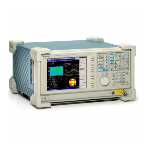
- Page 1 RSA3303B, RSA3308B, and RSA3408B Real-Time Spectrum Analyzers User Manual This document applies to firmware version 1.0 and above. www.tektronix.com 071-2395-00...
- Page 2 Copyright © Tektronix. All rights reserved. Licensed software products are owned by Tektronix or its subsidiaries or suppliers, and are protected by national copyright laws and international treaty provisions. Tektronix products are covered by U.S. and foreign patents, issued and pending. Information in this publication supersedes that in all previously published material.
- Page 3 Tektronix, with shipping charges prepaid. Tektronix shall pay for the return of the product to Customer if the shipment is to a location within the country in which the Tektronix service center is located. Customer shall be responsible for paying all shipping charges, duties, taxes, and any other charges for products returned to any other locations.
-
Page 5: Table Of Contents
Functional Overview ....................Interface Maps ....................Menu Operations....................Appendix A: Specifications ..................Electrical Characteristics..................Physical Characteristics ..................Environmental Characteristics ................Certifications and Compliances ................Digital IQ Output Connector Pin Assignment (RSA3408B Option 05 Only) ......Index RSA3303B, RSA3308B, and RSA3408B User Manual... - Page 6 Figure 30: Changing the step size for the center frequency ..........Figure 31: Changing the step size for the center frequency ..........Figure 32: Definition of the setup and hold time............... Figure 33: Digital IQ output connector pin assignment ............RSA3303B, RSA3308B, and RSA3408B User Manual...
- Page 7 Table 30: External output connector ................Table 31: Power requirements ................... Table 32: Physical characteristics ................Table 33: Environmental characteristics ................ Table 34: I OUTPUT connector pin assignment ............... Table 35: Q OUTPUT connector pin assignment.............. RSA3303B, RSA3308B, and RSA3408B User Manual...
-
Page 8: General Safety Summary
Do Not Operate in Wet/Damp Conditions. Do Not Operate in an Explosive Atmosphere. Keep Product Surfaces Clean and Dry. Provide Proper Ventilation. Refer to the manual’s installation instructions for details on installing the product so it has proper ventilation. RSA3303B, RSA3308B, and RSA3408B User Manual... - Page 9 DANGER indicates an injury hazard immediately accessible as you read the marking. WARNING indicates an injury hazard not immediately accessible as you read the marking. CAUTION indicates a hazard to property including the product. The following symbol(s) may appear on the product: RSA3303B, RSA3308B, and RSA3408B User Manual...
- Page 10 General Safety Summary RSA3303B, RSA3308B, and RSA3408B User Manual...
-
Page 11: Preface
Preface This is the operator manual for the RSA3303B, RSA3308B, and RSA3408B Real-Time Spectrum Analyzers. It covers the following information: Describes the capabilities of the analyzers and how to install them Explains how to operate the analyzer Lists specifications and accessories of the analyzer More detailed operating information is available through the online Help for the instruments and in the user manuals for the measurement options. -
Page 12: Conventions
A list of keys, controls, and/or menu items separated by an arrow symbol (→) indicates the order in which to perform the listed tasks. For example: Select RBW/FFT → Filter Shape... → Gaussian. viii RSA3303B, RSA3308B, and RSA3408B User Manual... -
Page 13: Product Overview
Product Overview The RSA3303B, RSA3308B, and RSA3408B are portable real-time spectrum analyzers. The real-time spectrum analyzer has a vastly different architecture from traditional tools, and is uniquely capable of capturing continuous, intermittent, or random signals with equal ease. The acquired data is analyzed in time, amplitude, phase, and frequency domains correlating with time. -
Page 14: Application
Product Overview Application The RSA3303B, RSA3308B, and RSA3408B can perform real-time analysis for the following purposes: Signal quality analysis of analog and digital modulation Understanding frequency and spectral occupancy behavior over time Capture and characterization of undesired, unknown, or interfering signals... -
Page 15: Installation
Tektronix representative. 3. It is recommended to keep the box and packing materials. You may need them to send this product to Tektronix for calibration or repair. CAUTION. The analyzer has exhaust fans on the side panel. Leave a space of at least 5 cm (2 in) on both sides for proper air circulation. -
Page 16: Figure 1: Setting Up The Stand
Installation Figure 1: Setting up the stand RSA3303B, RSA3308B, and RSA3408B User Manual... -
Page 17: Applying Power
Connecting the Power 1. Plug the power cord into the AC input on the rear panel. Cord Figure 2: AC Input (rear panel) 2. Connect the plug of the power cord to a properly grounded outlet. RSA3303B, RSA3308B, and RSA3408B User Manual... -
Page 18: Figure 3: Principal Power Switch (Rear Panel)
When you turn on the analyzer, the Windows operating system boots up. After several minutes, the analyzer application starts up. The initial screen appears. (See Figure 5.) The displayed spectrum represents the noise floor of the analyzer. RSA3303B, RSA3308B, and RSA3408B User Manual... -
Page 19: Figure 5: Initial Screen
(See page 16, Calibrating Gain.) CAUTION. Never apply signals with a combined amplitude greater than +30 dBm to the RF INPUT connector. Signals greater than +30 dBm can permanently damage the analyzer. (See Figure 6.) RSA3303B, RSA3308B, and RSA3408B User Manual... -
Page 20: Functional Check
Cal (RSA3300B). The spectrum of the calibration signal appears. e. Check that "INPUT: CAL" and "FREE RUN" are displayed in the status indicator at the upper right of the screen. (See Figure 7.) RSA3303B, RSA3308B, and RSA3408B User Manual... -
Page 21: Figure 7: Spectrum Of The Rsa3408B Calibration Signal (100 Mhz, About -20 Dbm)
Confirm that the span is 36 MHz (RSA3408B) or 15 MHz (RSA3300B) and the RBW is 100 kHz (RSA3408B) or 80 kHz (RSA3300B) in the setup display on the upper part of the screen. (See Figure 8.) RSA3303B, RSA3308B, and RSA3408B User Manual... -
Page 22: Figure 8: Setup Display
Confirm that A/D OVERFLOW is indicated in the red box at the top center of the screen. Make sure that -30 dBm is displayed on the upper left side of the graticule and that the spectrum waveform is distorted. (See Figure 9.) RSA3303B, RSA3308B, and RSA3408B User Manual... -
Page 23: Figure 9: Reference Level Setting And A/D Overflow Indicator
Press the RUN/STOP key on the front panel to stop data acquisition. Confirm that the trace display freezes and PAUSE is displayed in the status indicator at the top right of the screen. RSA3303B, RSA3308B, and RSA3408B User Manual... -
Page 24: Powering Off The Analyzer
To completely remove power to the analyzer, perform the shutdown just described, and then set the power switch on the rear panel to off. RSA3303B, RSA3308B, and RSA3408B User Manual... -
Page 25: Restarting The Analyzer
The Back Up tool is located in the System Tool folder in the Accessory folder of Windows. Start this tool to select the files and folders to back up. For more information, use Windows online help. RSA3303B, RSA3308B, and RSA3408B User Manual... -
Page 26: About Installation Of Other Applications
It is not recommended that you install other applications, including Microsoft Word, Excel, and Outlook, on the analyzer. If you install an external application, you do so at your own risk, keeping in mind that it may lower the performance of the analyzer. RSA3303B, RSA3308B, and RSA3408B User Manual... -
Page 27: Calibration
Calibrating Center Offset.) Calibrate DC Offset. This calibration cancels DC offset in baseband. (See page 17, Calibrating DC Offset.) Calibrate IF Flatness. Calibrates the IF (intermediate frequency) flatness. (See page 18, Calibrating IF Flatness (RSA3408B Only).) RSA3303B, RSA3308B, and RSA3408B User Manual... -
Page 28: Calibrating Gain
To run the gain calibration, do the following: 1. Press the CAL key on the front panel. 2. Press the Calibrate Gain side key. The calibration runs. It takes several seconds to complete the process. RSA3303B, RSA3308B, and RSA3408B User Manual... -
Page 29: Calibrating Center Offset
The DC offset calibration cancels DC offset that appears at 0 Hz in the baseband (RSA3408B: DC to 40 MHz, RSA3300B: DC to 20 MHz). When you change the amplitude setting and the DC offset is too obvious, run the DC offset calibration. RSA3303B, RSA3308B, and RSA3408B User Manual... -
Page 30: Calibrating If Flatness (Rsa3408B Only)
1. Press the CAL key on the front panel. 2. Press the Calibrate IF Flatness side key. The calibration runs. It takes several seconds to complete the process. Display Brightness Adjustment Adjust the brightness of the display according to your environment. RSA3303B, RSA3308B, and RSA3408B User Manual... -
Page 31: Confirming Performance
3. Turn the general purpose knob to adjust the brightness. The setting range is 0 to 100. Confirming Performance The electrical characteristics described in Appendix A: Specifications can be checked only by our service personnel. If you need any service, contact your local Tektronix representative. RSA3303B, RSA3308B, and RSA3408B User Manual... - Page 32 Calibration RSA3303B, RSA3308B, and RSA3408B User Manual...
-
Page 33: Functional Overview
This section describes the controls, connectors, display, and menu operation. Interface Maps Controls and Connectors The following Figures show the controls and connectors on the front, the side, and the rear panels. Figure 16: Front panel RSA3303B, RSA3308B, and RSA3408B User Manual... -
Page 34: Figure 17: Rear Panel
9. Power switch (ON/STANDBY). (See page 6, Turning on the Analyzer.) 10. LED. Green on operating, orange on standby. CAUTION. Applying a signal of more than +30 dBm may damage the instrument. Figure 17: Rear panel RSA3303B, RSA3308B, and RSA3408B User Manual... - Page 35 PC. (See Table 30 on page 57.) 8. AC input. Connect AC power cable. 9. PRINCIPAL POWER SWITCH. When this switch is on, the internal standby circuit is energized. (See page 6, Turning on the Analyzer.) RSA3303B, RSA3308B, and RSA3408B User Manual...
-
Page 36: Figure 18: Side Panel
4. VGA output connector. Sends the display of this instrument to another monitor. 15 pin D-sub connector (female) 5. USB connector. Connect a mouse, a keyboard and a printer that meets USB specifications. RSA3303B, RSA3308B, and RSA3408B User Manual... -
Page 37: Figure 19: Operation With Mouse And Keyboard
G or g key Alphanumeric input Giga (10 ). Press ENTER to complete entry of the value. m key Alphanumeric input milli (10 ). Press ENTER to complete entry of the value. RSA3303B, RSA3308B, and RSA3408B User Manual... -
Page 38: Figure 20: Display Screen Configuration (Rsa3408B Shown)
N or n key Alphanumeric input nano (10 ). Press ENTER to complete entry of the value. Display Screen The following Figure shows the elements of the display screen. Figure 20: Display screen configuration (RSA3408B shown) RSA3303B, RSA3308B, and RSA3408B User Manual... -
Page 39: Figure 21: Status Display (Rsa3408B Shown)
Pre-trigger data has been acquired, and the instrument is waiting for a trigger event. Pre-trigger data has been acquired, and a trigger event has been TRIG’D detected. The instrument is now acquiring post-trigger data. RSA3303B, RSA3308B, and RSA3408B User Manual... -
Page 40: Figure 22: Pre- And Post-Trigger Regions
When controlling this instrument through GPIB, you can disable all the keys on the front panel except the power switch using the :SYSTEM:KLOCK command. At this time, the message "PANEL LOCK" is displayed on the top side key. (See Figure 23.) Figure 23: Key lock display RSA3303B, RSA3308B, and RSA3408B User Manual... -
Page 41: Figure 24: Setup Display (Rsa3408B Shown)
Bandwidth) for compatibility with swept spectrum analyzers. Indicates NBW (Noise Bandwidth) instead of RBW when FFT-processed data does not go through RBW process. Trace 1 and 2 Indicates the Trace 1 and 2 trace type. RSA3303B, RSA3308B, and RSA3408B User Manual... -
Page 42: Menu Operations
Up to nine soft keys can be displayed down the right side of the screen. (See Figure 25.) Cancel - Back is always displayed at the top, and the other eight keys select menu items. RSA3303B, RSA3308B, and RSA3408B User Manual... -
Page 43: Figure 25: Examples Of Menu Item Display
Functional Overview Figure 25: Examples of menu item display NOTE. When the setting is prohibited or is not available, the item is displayed in gray. RSA3303B, RSA3308B, and RSA3408B User Manual... -
Page 44: Figure 26: Numeric Setting Menu
An example numeric input field is shown below. In this type of field, you can change the numeric value by turning the general purpose knob, by pressing the up/down (▲▼) keys, or by entering a value using the keypad. Figure 26: Numeric setting menu RSA3303B, RSA3308B, and RSA3408B User Manual... -
Page 45: Figure 27: Changing Value With The Knob
(See page 34, Changing the Step Size.) The changed value is immediately reflected on the analyzer settings and displays. Entering a Value Using the Keypad. You can enter values using the front panel keypad. (See Figure 29.) RSA3303B, RSA3308B, and RSA3408B User Manual... -
Page 46: Figure 28: Changing Value With The Keypad
In the example below, the step size for the start frequency is set to 100 kHz; the displayed frequency set value changes by 100 kHz step for each press of the up or down key. RSA3303B, RSA3308B, and RSA3408B User Manual... -
Page 47: Figure 30: Changing The Step Size For The Center Frequency
Center Freq Step Same As Span. Useful for quickly analyzing a larger frequency area without overlapping span windows. Figure 31: Changing the step size for the center frequency RSA3303B, RSA3308B, and RSA3408B User Manual... - Page 48 Functional Overview RSA3303B, RSA3308B, and RSA3408B User Manual...
-
Page 49: Appendix A: Specifications
Unless otherwise stated, the following tables of electrical characteristics and features apply to the analyzer after a 20 minute warm-up period (within the environmental limits) and after all calibration procedures have been carried out. RSA3303B, RSA3308B, and RSA3408B User Manual... -
Page 50: Electrical Characteristics
RF/RF1, Frequency = 2 GHz, Span = 1 MHz Marker: ±1.2 kHz; Carrier frequency measurement: ±210 Hz RF2, Frequency = 5 GHz, Span = 1 MHz (RSA3308B only) Marker: ±1.5 kHz; Carrier frequency measurement: ±510 kHz RF3, Frequency = 7 GHz, Span = 1 MHz (RSA3308B only) Marker: ±1.7 kHz;... -
Page 51: Table 7: Rsa3300B Spectrum Purity
-87 dBc/Hz 1 kHz (RSA3308B only) 10 kHz -104 dBc/Hz -105 dBc/Hz 20 kHz -105 dBc/Hz 30 kHz -112 dBc/Hz 100 kHz -128 dBc/Hz 1 MHz 5 MHz -130 dBc/Hz -130 dBc/Hz 7 MHz RSA3303B, RSA3308B, and RSA3408B User Manual... -
Page 52: Table 9: Rsa3408B Noise Sideband
1 kHz -110 dBc/Hz 10 kHz -110 dBc/Hz 20 kHz -110 dBc/Hz 30 kHz -112 dBc/Hz 100 kHz -132 dBc/Hz 1 MHz 5 MHz -138 dBc/Hz -138 dBc/Hz 7 MHz -138 dBc/Hz 10 MHz RSA3303B, RSA3308B, and RSA3408B User Manual... - Page 53 1 kHz -108 dBc/Hz 10 kHz 20 kHz -108 dBc/Hz -108 dBc/Hz 30 kHz -113 dBc/Hz 100 kHz -134 dBc/Hz 1 MHz -139 dBc/Hz 5 MHz 7 MHz -139 dBc/Hz -139 dBc/Hz 10 MHz RSA3303B, RSA3308B, and RSA3408B User Manual...
-
Page 54: Table 10: Input
Typical <1.4 (300 kHz to 40 MHz, RF attenuation ≥10 dB) <1.3 (40 MHz to 3 GHz, RF attenuation ≥10 dB) <1.4 (3 GHz to 8 GHz, RF attenuation ≥10 dB (RSA3308B and RSA3408B only)) Maximum input level Maximum DC voltage ±0.2 V (RF (RSA3303B), RF1 to 3) -
Page 55: Table 11: Rsa3408B Amplitude
RF: ±0.5 dB (at 100 MHz, -20 dBm signal, 0 dB attenuation) Input attenuator setting uncertainty ±0.2 dB (at 100 MHz) Level linearity in display range ±0.2 dB (0 to -50 dBfs); ±0.12 dB (0 to -50 dBfs, Typical) RSA3303B, RSA3308B, and RSA3408B User Manual... -
Page 56: Table 12: Rsa3300B Amplitude
Baseband: -30 to +20 dBm (2 dB step) RF/RF1: -51 to +30 dBm (1 dB step) RF2/RF3 (RSA3308B only): -50 to +30 dBm (1 dB step) Option 03 IQ input: -10 to +20 dBm (10 dB step) Accuracy (-10 to -50 dBm) ±0.2 dB (at 50 MHz, 10 dB attenuation, 20 to 30 °C) - Page 57 -40 dBm (local frequency 4.2 to 5 GHz) -55 dBm (local frequency 5 to 6 GHz) -60 dBm (local frequency 6 to 7 GHz) -60 dBm (local frequency 7 to 7.7 GHz, RSA3308B and RSA3408B only) RSA3408B Image Suppression (Typical) 75 dB (40 MHz to 3.5 GHz) 70 dB (3.5 GHz to 8 GHz)
- Page 58 -93 dBm (Span = 20 MHz) RF, 0.5 to 3 GHz (RSA3303B) -90 dBm (Span = 2.5 GHz) RF1, 0.5 to 3 GHz (RSA3308B) -90 dBm (Span = 3 GHz) RF2, 3.5 to 6.5 GHz (RSA3308B) -85 dBm (Span = 3 GHz)
-
Page 59: Table 14: Rsa3408B Acquisition
Minimum: 1024 samples modes) Maximum: 16,384,000 samples (Standard); 65,536,000 samples (Option Acquisition length setting resolution 1024 samples (Real Time S/A, Demod, and Time modes) Acquisition memory size Standard: 64 MB; Option 02: 256 MB RSA3303B, RSA3308B, and RSA3408B User Manual... -
Page 60: Table 15: Rsa3300B Acquisition
Power (Span BW), Frequency mask (Option 02), External Pre/Post trigger setting Trigger position is settable from 0 to 100% of total data length. Power trigger 0 to -40 dBfs Frequency mask trigger (Option 02) RSA3303B, RSA3308B, and RSA3408B User Manual... -
Page 61: Table 17: Rsa3408B Rbw (Resolution Bandwidth)
1 kHz < Span ≤2 kHz 2 Hz 100 Hz ≤ Span ≤1 kHz 1 Hz Table 18: RSA3300B RBW (Resolution Bandwidth) Characteristics Description Filter shape Gaussian, Rectangle, Root Nyquist Setting range 1 Hz to 10 MHz RSA3303B, RSA3308B, and RSA3408B User Manual... -
Page 62: Table 19: Trace And Display Line
Trace type Normal, Average, Max Hold, Min Hold Display detector Positive peak, Negative peak, and Positive-Negative peak Display line Horizontal line 1 and 2, Vertical line 1 and 2 Table 20: Display Characteristics Description Views RSA3303B, RSA3308B, and RSA3408B User Manual... -
Page 63: Table 21: Rsa3408B Measurement Function
Description Accuracy (Typical) AM demodulation ±2% (-10 dBfs input at center, 10 to 60% modulation depth) PM demodulation ±3° (-10 dBfs input at center) FM demodulation ±1% of span (-10 dBfs input at center) RSA3303B, RSA3308B, and RSA3408B User Manual... -
Page 64: Table 24: Pulse Measurement
Binary, Octal, Hexadecimal AM/AM Measured amplitude versus Reference amplitude 1 dB compression measurement AM/PM Phase error versus Reference amplitude CCDF Probability of exceed versus Power level, Crest factor measurement Probability of occurrence versus Power level Accuracy RSA3303B, RSA3308B, and RSA3408B User Manual... - Page 65 Center frequency = 3 GHz 0.7% 100 kHz 1 MHz 0.7% 1.5% 4 MHz 2.9% 10 MHz Center frequency = 5 GHz 0.7% 100 kHz 1 MHz (RSA3308B only) 0.7% 1.5% 4 MHz 3.0% 10 MHz RSA3303B, RSA3308B, and RSA3408B User Manual...
- Page 66 Center frequency = 3 GHz 0.7% 100 kHz 1 MHz 0.7% 1.5% 4 MHz 2.9% 10 MHz Center frequency = 5 GHz 0.7% 100 kHz 1 MHz (RSA3308B only) 0.7% 1.5% 4 MHz 3.0% 10 MHz RSA3303B, RSA3308B, and RSA3408B User Manual...
-
Page 67: Table 26: Aclr Measurement (Option 30)
1 MHz (RSA3308B only) 0.5% 1.2% 4 MHz 2.5% 10 MHz Table 26: ACLR measurement (Option 30) Characteristics Description ACLR (3GPP down link, Test model 1, 1 DPCH ch, 1800 to 2200 MHz carrier frequency) RSA3303B, RSA3308B, and RSA3408B User Manual... -
Page 68: Table 27: Rsa3408B Wireless Lan Measurement (Option 29)
20 Hz (2 kHz span) 10 Hz (1 kHz span) 5 Hz (500 Hz span) 2 Hz (200 Hz span) 1 Hz (100 Hz span) RBW accuracy +1%, –7% RBW range 1 Hz to 5 MHz (1–2–3–5 sequence) RSA3303B, RSA3308B, and RSA3408B User Manual... -
Page 69: Table 29: Controller
Preamp power connector Connector type LEMO 6 poles Pin assignment Pin 1: NC, Pin 2: ID1, Pin 3: ID2, Pin 4: -12 V, Pin 5: GND, Pin 6: +12 V RSA3408B Digital I/Q output (Option 05) RSA3303B, RSA3308B, and RSA3408B User Manual... -
Page 70: Figure 32: Definition Of The Setup And Hold Time
5 A rms at 50 Hz (90 V line with 5% clipping) Surge current Maximum 52 A peak (25 °C) for ≤5 line cycles after the product has been turned off for at least 30 s. RSA3303B, RSA3308B, and RSA3408B User Manual... -
Page 71: Physical Characteristics
(20 G), half-sine, 11 ms duration Three shocks in each direction along each major axis, total of 18 shocks Cooling clearance Bottom 20 mm (0.79 in) Both sides 50 mm (1.97 in) Rear 50 mm (1.97 in) RSA3303B, RSA3308B, and RSA3408B User Manual... -
Page 72: Certifications And Compliances
Australia / New Zealand Complies with EMC provision of Radiocommunications Act per the following standard, in accordance with ACMA: Declaration of Conformity - EMC EN 61326:1997. EMC requirements for electrical equipment for measurement, control, and laboratory use. RSA3303B, RSA3308B, and RSA3408B User Manual... - Page 73 Pollution Degree 4. Pollution that generates persistent conductivity through conductive dust, rain, or snow. Typical outdoor locations. Pollution Degree Pollution Degree 2 (as defined in IEC 61010-1). Note: Rated for indoor use only. RSA3303B, RSA3308B, and RSA3408B User Manual...
-
Page 74: Digital Iq Output Connector Pin Assignment (Rsa3408B Option 05 Only)
IQ output enable signal input Open: IQ output disable Connect to GND: IQ output enable Ground Ground EXT_I0- I output data (bit 0), LVDS EXT_I0+ EXT_I1- I output data (bit 1), LVDS EXT_I1+ EXT_I2- I output data (bit 2), LVDS EXT_I2+ RSA3303B, RSA3308B, and RSA3408B User Manual... - Page 75 Ground EXT_I12- I output data (bit 12), LVDS EXT_I12+ EXT_I13- I output data (bit 13), LVDS EXT_I13+ EXT_I14- I output data (bit 14), LVDS EXT_I14+ EXT_I15- I output data (bit 15), LVDS EXT_I15+ Ground RSA3303B, RSA3308B, and RSA3408B User Manual...
-
Page 76: Table 35: Q Output Connector Pin Assignment
EXT_Q4+ EXT_Q5- Q output data (bit 5), LVDS EXT_Q5+ EXT_Q6- Q output data (bit 6), LVDS EXT_Q6+ EXT_Q7- Q output data (bit 7), LVDS EXT_Q7+ Ground EXT_Q8- Q output data (bit 8), LVDS EXT_Q8+ RSA3303B, RSA3308B, and RSA3408B User Manual... - Page 77 Q output data (bit 12), LVDS EXT_Q12+ EXT_Q13- Q output data (bit 13), LVDS EXT_Q13+ EXT_Q14- Q output data (bit 14), LVDS EXT_Q14+ EXT_Q15- Q output data (bit 15), LVDS EXT_Q15+ Ground Not used RSA3303B, RSA3308B, and RSA3408B User Manual...
- Page 78 Appendix A: Specifications RSA3303B, RSA3308B, and RSA3408B User Manual...
-
Page 79: Index
Electrical characteristics, 38 operation, 30 Environmental characteristics, 59 Menu keys, 22 Troubleshooting, 13 Mouse operation, 25 Features, 1 Functional check, 8 UNCAL, 7 Unpacking, 3 NBW, setup display, 29 Numeric input, 32 Gain calibration, 16 RSA3303B, RSA3308B, and RSA3408B User Manual...
Need help?
Do you have a question about the RSA3308B and is the answer not in the manual?
Questions and answers