Grindmaster 3311 User Manual
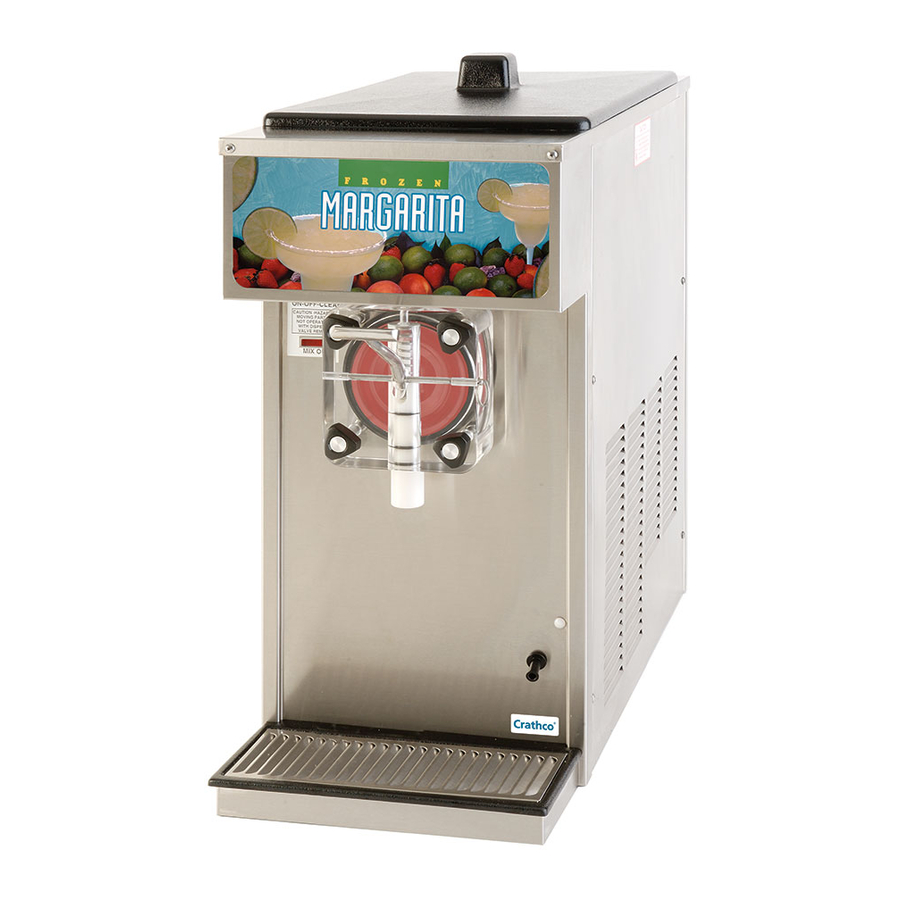
Beverage freezer
Hide thumbs
Also See for GRINDMASTER 3311:
- User manual (37 pages) ,
- Specification sheet (2 pages) ,
- Parts list (1 page)
Table of Contents

Related Manuals for Grindmaster GRINDMASTER 3311


Summary of Contents for Grindmaster GRINDMASTER 3311
- Page 1 Model 3311 Beverage Freezer Manual Grindmaster Corporation 4003 Collins Lane Louisville, KY 40245 USA (502) 425-4776 (800) 695-4500 FAX (502) 425-4664 www.grindmaster.com © Grindmaster Corporation, 2004 0604 Form # WH-312-02 PRINTED IN USA Part # W0600110...
-
Page 3: Table Of Contents
Safety Precautions ... Freezer Applications & Specifications ... Installation ... Operation and Adjustments ... Care & Cleaning ... Maintenance ... Troubleshooting ... 14 Key Parts Identification ... 15 Assembly Diagrams ... 16 - 23 Wiring Diagrams ... 24 - 31 Refrigeration Diagrams ... -
Page 4: Safety Precautions
1. Read and understand the operating instructions in this manual thoroughly. Only allow properly trained persons to operate this machine. 2. Note all warning labels on the freezer. If any warning labels are missing or damaged replace them immediately. 3. Do not wear loose fitting garments or jewelry which could cause a serious accident. -
Page 5: Freezer Applications & Specifications
Contact your local health department regarding its regulations for proper mix handling and storage. Carburetor Assembly Your new freezer uses a metering device, known as a carburetor, to feed the proper ratio of mix and air into the freez- ing cylinder (and to prevent frozen product from rinsing out of the freezing cylinder). -
Page 6: Installation
(Leg Kit Part # W0890220 (4) 4” Legs) 2. Make sure freezer is to be placed in a location that is within 6’ of a properly grounded circuit and allows adequate space at each side and above for proper air circulation. - Page 7 13. Remove the drip tray kit from the bubble wrap. Separate the parts and remove the protective coating. The drip tray is mounted on two screws that are located on the lower front of the freezer cabinet. 14. Place the key hole slot of the drip tray support bracket (W0471022) on to these screws and tighten the screws.
-
Page 8: Operation And Adjustments
• Concealed Air Filter - Prevents dust from clogging the condenser. Ideal for applications near beaches. Helps maintain maximum air flow and optimum freezer performance. See Figure F. NSF approved. Part # W0890200 stainless steel; W0890208 black. • Exposed Air Filter - Similar to concealed air filter. Not NSF approved. - Page 9 (See Figure L) 4. Reinstall the side panel, reconnect power. 5. Turn freezer to “ON” and allow it to freeze to desired consistency. 6. Check product. Repeat process until desired consistency is achieved. NOTE: When making changes to a colder (thicker) setting, recheck consistency again after the compressor has cycled off.
-
Page 10: Care & Cleaning
Drain and Rinse 1. If the freezer is empty, proceed to Disassembly and Cleaning. If there is product in the freezer, turn the front panel switch to “CLEAN”. Most users schedule cleaning when product in the hopper is low to minimize product loss. - Page 11 (Figure T) 12. The exterior of the freezer should be cleaned as needed with a cloth towel. CAUTION: Coarse rags, abrasive cleaners and excessive force can damage and/or scratch the surfaces of the freezer.
- Page 12 Use a large brush to sanitize all hopper surfaces. (Figure DD) 11. Turn panel switch to “CLEAN” and allow freezer to run for 5 minutes. 12. Open dispensing valve and drain solution. Allow the dasher to push remaining sanitizer out of the freezing cylinder.
-
Page 13: Maintenance
Suggested Daily Maintenance 1. Clean, lubricate and sanitize the freezer following guidelines. 2. Clean the exterior of the freezer using a soft wet cloth. (Wipe down spinner if attached) 3. Empty drip tray. Parts Replacement Schedule... - Page 14 • Check V-belt tension (should be 1/2” - 5/8”) and verify all set screws are tightened - adjust if out of range. Replace belt once per year minimum. • Verify compressor operation and freezer controller operation. • Check electrical connections (outlet should be properly grounded with amperage capacity equal to or over the amperage specified on the serial tag).
- Page 15 How to Clean Condenser (Air-Cooled Unit Only) NOTE: Loss of refrigeration efficiency will result if condenser is allowed to become dirty. Excessive compressor run time or loss of capacity are a good indication that the condenser needs to be cleaned. 1.
-
Page 16: Troubleshooting
GENERAL TROUBLESHOOTING Freezer problems originate from three sources - improper operation, mix problems or mechanical malfunction. Always check for improper operation and mix problems first, as they are the most common cause of most equipment problems. CAUTION: Always disconnect power before attempting any maintenance procedures. - Page 17 Model 3311 Page 15...
- Page 18 Exploded View Model 3311 115V Air-Cooled Model ITEM NO. PART NO. DESCRIPTION W0201272 Cylinder Assembly W0451067 Driveshaft, Slush W0380025 Bearing, 1” Bore W0210106 Base Pan Assembly W0200123 Compressor, #AKA171AT032A4, 115V, 3PH, 60HZ W0200256 Condenser Coil, Air, CFB W0321029 Fan Assembly W0321026 Drive Motor Assembly W0210083...
- Page 19 Exploded View Model 3311 220V Air-Cooled Model ITEM PART NUMBER DESCRIPTION W0570045 BALLAST W0600110 OWNERS MANUAL W0660060 PLASTIC SHIPPING BAG W0600121 HEADER INSTALL INSTR SHEET W0600073 CAUTION RUBBER MAT W0631903 SANITIZER PACKETS W0600159 WARRANTY CARD W0801023 PACKAGING ASSEMBLY W0890218 DRIP PAN KIT W0430026 STANDARD DASHER W0340022...
- Page 20 Exploded View Model 3311 115V Water-Cooled Model ITEM PART NUMBER DESCRIPTION W0570045 BALLAST W0600110 OWNERS MANUAL W0660060 PLASTIC SHIPPING BAG W0600121 HEADER INSTALL INSTR SHEET W0600073 CAUTION RUBBER MAT W0631903 SANITIZER PACKETS W0600159 WARRANTY CARD W0801023 PACKAGING ASSEMBLY W0890218 DRIP PAN KIT W0430026 STANDARD DASHER W0340022...
- Page 21 Model 3311 Base Assembly 115V Air-Cooled Model PART ITEM DESCRIPTION NUMBER W0210083 FRAME ASSEMBLY W0201001 COMPRESSOR ASSEMBLY W0201002 CONDENSER ASSEMBLY W0321029 FAN SUB-ASSEMBLY W0321026 DRIVE MOTOR ASSEMBLY W0210106 BASE PAN ASSEMBLY W0611410 RIVET, MAGNA-LOK W0611247 1/4 INT. TOOTH LK. WSHR. W0611074 1/4-20 HEX NUTS W0611082...
-
Page 22: Part Number Description
Model 3311 Base Assembly 220V Air-Cooled Model ITEM PART NUMBER DESCRIPTION W0210083 FRAME ASSEMBLY W0201007 COMPRESSOR ASSEMBLY W0201002 CONDENSER ASSEMBLY W0321040 FAN SUB-ASSEMBLY W0321041 DRIVE MOTOR ASSEMBLY W0210106 BASE PAN ASSEMBLY Page 20 ITEM PART NUMBER DESCRIPTION W0611410 RIVET, MAGNA LOCK W0611247 1/4 INT. - Page 23 Model 3311 Base Assembly 115V Water-Cooled Model ITEM PART NUMBER DESCRIPTION W0210068 BASE PAN W0201001 COMPRESSOR ASSEMBLY W0321026 DRIVE MOTOR ASSEMBLY W0210083 FRAME ASSEMBLY W0611410 RIVET, MAGNA LOCK W0611082 5/16-18 FLANGE NUT W0200412 COMPRESSOR SPACER W0200413 COMPRESSOR GROMMET * See condenser assembly on page 34. Model 3311 Page 21...
- Page 24 Model 3311 Electrical Box Assembly 115V Model (AC/WC Units) Page 22 Model 3311...
- Page 25 Model 3311 Electrical Box Assembly 220V Air-Cooled Model ITEM PART NUMBER DESCRIPTION W0572287 ELECTRICAL BOX W0570054 LIGHT SOCKET W0570235 TERMINAL BLOCK W0570635 CONTACTOR W0570667 RUN CAPACITOR W0570666 START CAPACITOR W0570651 HEAT SEQUENCER WO630812 CLIP, CAPACITOR W0570940 TOGGLE SWITCH W0610015 6-32 X 1/4 SLOTTED SCREW 86827 6-32 HEX NUT Z/P Model 3311...
-
Page 26: Wiring Diagrams
Model 3311 Wiring Diagram 115V Air-Cooled Model Page 24 ITEM PART NO. DESCRIPTION W0570018 INDICATOR LIGHT W0570638 COMPRESSOR RELAY W0572032 TRANSFORMER SUB-ASSY W0570651 TIME DELAY RELAY W0570235 TERMINAL BLOCK W0570603 START CAPACITOR W0570617 RUN CAPACITOR W0572192 MIX LOW SUB-ASSY. W0572068 POWER CORD W0630801 TIE WRAPS... - Page 27 Model 3311 Wiring Diagram 220V Air-Cooled Model ITEM PART NUMBER DESCRIPTION W0570872 CONTACTOR RELAY W0570651 TIME DELAY RELAY W0570940 TOGGLE SWITCH W0570235 TERMINAL BLOCK W0570871 TRANSFORMER W0570018 INDICATOR LIGHT W0570667 RUN CAPACITOR W0570666 START CAPACITOR W0570559 COMPRESSOR RELAY W0570055 LIGHT BULB W0570054 LIGHT SOCKET W0570053...
- Page 28 Model 3311 Wiring Diagram Water-Cooled Model ITEM PART NUMBER DESCRIPTION HIGH PRESSURE W0650428 CUT-OUT SWITCH W0570924 SWITCH W0570043 FLORESCENT LIGHT BULB W0570044 LIGHT SOCKET W0570045 CORE & COIL BALLAST W0572068 POWER CORD W0572192 LOW MIX SUB-ASSY Page 26 ITEM PART NUMBER DESCRIPTION W0570604 RUN CAPACITOR...
- Page 29 Model 3311 Compressor Wiring START CAPACITOR RUN CAPACITOR COMPRESSOR RELAY BLACK YELLOW YELLOW 115V Air-Cooled Model Model 3311 YELLOW WIRES TO BLACK COMPRESSOR YELLOW 115V Water-Cooled Model 220V Air-Cooled Model Page 27...
- Page 30 Model 3311 Ladder Diagram 115V Air-Cooled Model Page 28 Model 3311...
- Page 31 Model 3311 Ladder Diagram 220V Air-Cooled Model Model 3311 Page 29...
- Page 32 Model 3311 Ladder Diagram 115V Water-Cooled Model Page 30 Model 3311...
- Page 33 Model 3311 (AC/WC Units) Spinner Hook-Up 115V Model Model 3311 Spinner Hook-Up 220V Model Model 3311 Page 31...
- Page 34 Model 3311 Refrigeration 115V Air-Cooled Model Page 32 Model 3311...
- Page 35 Model 3311 Refrigeration 220V Air-Cooled Model Model 3311 Page 33...
- Page 36 Model 3311 Refrigeration 115V Water-Cooled Model ITEM PART NUMBER DESCRIPTION W0200123 COMPRESSOR W0200250 CONDENSER, WATER COOLED W0650602 WATER VALVE, 3/8 V-46 AA-1C W0620031 BULKHEAD FITTING WITH JAM NUT W1650401 HIGH PRESSURE CUT OUT W0210051 WATER LINE SUPPORT BRACKET W0200311 DRIER CAPILLARY TUBE ASSEMBLY W0620031 90 DEG.
- Page 37 Model 3311 Refrigeration Schematic (AC Units) 115V & 220V Models Model 3311 Page 35...
- Page 38 Model 3311 Refrigeration Schematic Water-Cooled Model Page 36 Model 3311...
- Page 39 Model 3311 Page 37...
- Page 40 Grindmaster® Coffee Grinders and Brewers • Espressimo® Espresso Machines • Crathco® Hot Beverage Dispensers Crathco® Cold and Frozen Beverage Dispensers • American Metal Ware® Coffee and Tea Systems Tel (502) 425-4776 • Fax (502) 425-4664 • 1-800-695-4500 P.O. Box 35020 • Louisville, KY 40232 • USA 0604 Form # WH-312-02 ©...
Need help?
Do you have a question about the GRINDMASTER 3311 and is the answer not in the manual?
Questions and answers