Table of Contents
Advertisement
Quick Links
HDX-135-345 Wireless Rate-of-Rise Heat Sensor Installation Instructions
Introduction
The Interlogix HDX series wireless heat detectors use
electronic processing to detect temperature Rate-of-Rise
and fixed heat set point conditions plus a learn mode
wireless transmitter in one unit. The micro-processor trips
the transmitter when the temperature at the detector location
reaches a fixed temperature of 135°F (57°C) or senses a
rate of rise at 12°F to 15ºF (6.7 to 8.3ºC)
Model
HDX-135-345
Wireless 135ºF (57ºC) Rate-of-Rise Heat
Sensor, 345 MHz Wireless, Compatible with
Honeywell and 2GIG Wireless Receivers
Installation
Use the following installation guidelines:
•
Heat detectors should be installed to provide property
protection. Reliance should not be placed on heat
sensors for life safety. Where life safety is involved,
smoke sensors must also be installed.
•
The detectors allow for normal temperature fluctuations,
however, ceiling temperatures should not exceed 100°F
(38°C)
•
Mount the detector in a central location of the area to be
protected, either on the ceiling or on a wall.
•
If mounting on a ceiling, the detector must be at least 4
in. (10 cm) away from any walls.
•
If mounting on a wall, the top of the detector must be
within 4 to 6 in. (10 to 15 cm) of the ceiling.
•
The UL maximum spacing allowance of the detector is
50 x 50 ft. (15 x 15 m). Refer to the NFPA Standard 72
for application requirements.
•
Do not mount the detector close to devices that change
temperature rapidly, such as ovens, heat vents,
furnaces, or boilers.
Enrolling
The HDX-135-345 is compatible with Honeywell and 2GIG
wireless receivers. These panels must learn (program) the
detector ID codes in order to respond to detector signals. For
complete programming instructions refer to the specific
466-5304 • REV A • 20January17
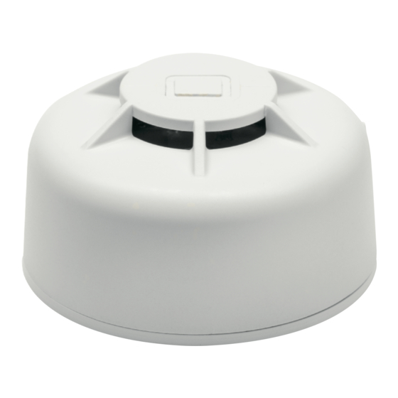
Figure 1
control panel instruction guides.
To add the sensor to panel memory:
Honeywell™
The HDX-135-345 must be enrolled in the control panel
before it can operate in the system. The heat protection zone
must be enrolled as Loop 1 and "Input Type" 3 (supervised
RF). Tamper is transmitted as Loop 4, but does not require
programming.
1. Place the panel in program mode.
2. Enter the zone number to be programmed.
3. Enter the zone type when prompted. Program as a Fire
zone type [9]
4. When prompted, enter Input Type [03] (3 on some
panels) – Supervised RF Transmitter
5. Remove pull tab from sensor battery
6. When prompted for the serial number, transmit from the
detector by activating (press and release) the tamper
switch (Figure 2).
7. When serial number is displayed, transmit from sensor
again by activating tamper switch again. The current
loop number will begin to flash (4).
8. Manually change the loop number to loop number [1].
Note: The fire protection zone enrolled must always be
Loop 1. Otherwise, fire annunciations will not be
reported by the control
9. Exit programming when complete. Test the sensor after
enrolling into the system. Refer to the Testing section in
this guide.
Tamper
Figure 2: Tamper
2GIG®
The following procedure describes how to learn-in the HDX-
135-345 heat sensor into the 2GIG control panel.
1. Select RF sensor #(01 to 48)
2. Select RF sensor type [09] Smoke/Heat
3. Select RF sensor equipment code. Enter code 0895
1
Advertisement
Table of Contents

Related Manuals for Interlogix HDX-135-345


Summary of Contents for Interlogix HDX-135-345
- Page 1 The micro-processor trips the transmitter when the temperature at the detector location The HDX-135-345 must be enrolled in the control panel reaches a fixed temperature of 135°F (57°C) or senses a before it can operate in the system. The heat protection zone rate of rise at 12°F to 15ºF (6.7 to 8.3ºC)
- Page 2 4. With panel in learn-in mode (press Shift then Learn) cause a tamper by pressing and then release tamper switch (Figure 2). The correct TX ID should appear. Accept by pressing OK. Magnet Mark and Location 5. Select RF sensor equipment age [0] New 6.
- Page 3 All rights reserved. Visit us online at www.interlogix.com. For technical support, see www.interlogix.com/support Trademarks Interlogix is a registered trademark of United Technologies Corporation. Interlogix is part of UTC Climate, Controls & Security, a Product Ordering unit of United Technologies Corporation. Model HDX-135-345 Wireless 135ºF (57ºC) Rate-of-Rise Heat...
Need help?
Do you have a question about the HDX-135-345 and is the answer not in the manual?
Questions and answers