Table of Contents
Advertisement
Quick Links
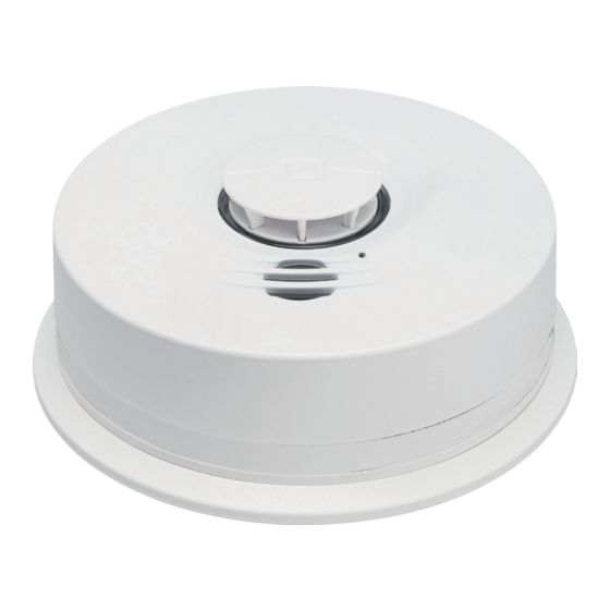
HDX-135Z-433
Wireless Interconnected
Heat/Freeze sensor 433-63
User Guide
Attention: Please take a few minutes to thoroughly read this user guide which should be
saved for future reference.
NOTE: Leave this user guide with the home owner.
You do NOT need a home wi-fi system to use these units. Multiple wireless units create
their own independent wireless alarm network.
P/N 1006-7201-00 • REV A • ISS 14MAR18
©2018 United Technologies Corporation
1
Advertisement
Table of Contents

Related Manuals for Interlogix HDX-135Z-433


Summary of Contents for Interlogix HDX-135Z-433
- Page 1 HDX-135Z-433 Wireless Interconnected Heat/Freeze sensor 433-63 User Guide Attention: Please take a few minutes to thoroughly read this user guide which should be saved for future reference. NOTE: Leave this user guide with the home owner. You do NOT need a home wi-fi system to use these units. Multiple wireless units create their own independent wireless alarm network.
- Page 2 Teach children how to respond to the alarm and that they should never play with the unit. Your Interlogix heat alarm was designed for use in a residential environment. It is not designed for use in a recreational vehicle (RV) or boat.
-
Page 3: Table Of Contents
Contents 1. Heat Alarm: What To Do When The Alarm Sounds............4 2. Other Alarm Visual And Audible Indicators ..............5 3. Troubleshooting Guide ...................... 7 4. Introduction, Product Features & Specifications............9 5. Limitations Of Heat Alarms....................13 6. Recommended Locations For Heat Alarms ..............14 7. -
Page 4: Heat Alarm: What To Do When The Alarm Sounds
1. Heat Alarm: What To Do When the Alarm Sounds Heat alarm pattern is three long beeps, a 1.5 second pause, and three long beeps repeating. The red LED blinks in time with alarm pattern. • Alert small children in the home as well as anyone else that might have difficulty recognizing the importance of the alarm sounding or that might have difficulty leaving the area without help. -
Page 5: Other Alarm Visual And Audible Indicators
2. Other Alarm Visual and Audible Indicators Operational Mode Visual Indications Audible Indications Action/Note: Normal Operation One GREEN LED blink (standby) every 60 seconds. Freeze Warning One RED LED blink None None. Flashing continues every 20 seconds. while condition exists. Tamper Condition One RED LED blink Alarm chirps once when tamper... - Page 6 Operational Mode Visual Indications Audible Indications Action/Note: Heat Alarm Memory Alternating flashing None Press test button to clear alarm (alarm has experienced RED and AMBER memory, or allow 1 hour time out an alarm event within LEDs. 1 second RED/1 to return to normal operation.
-
Page 7: Troubleshooting Guide
3. Troubleshooting Guide Trouble Condition Visual Indications Audible Indications Action: Fault Mode/Fatal One AMBER Alarm chirps 1. Push the Test/Hush button once to attempt to Error LED blink every 5 every 30 seconds. reset the alarm. seconds. The RED LED will blink out an Error Code (number of blinks) when the Test/Hush button is pushed/released once.Report the number of blinks to Customer Service, if needed. - Page 8 Trouble Condition Visual Indications Audible Indications Action: Low Battery One AMBER LED blink Alarm chirps every 60 Remove, discharge, then dispose of every 5 seconds. seconds alarm. Replace as soon as possible. End of Alarm One AMBER LED blink Double alarm chirp every The RED LED will blink out an Error Life (EOL) every 5 seconds.
-
Page 9: Introduction, Product Features & Specifications
4. Introduction, Product Features and Specifications Introduction The HDX-135Z-433 supervised heat alarm with freeze sensor is a self-diagnostic alarm with wireless interconnection, 10-yr sealed battery and sensor life, built-in sounder, diagnostic/status LED, integrated fixed temperature and rate-of-rise heat sensor and a pre-freeze condition indicator. - Page 10 Product Features and Specifications: Power 3V DC non-replaceable sealed lithium batteries Temperature sensor NTC Thermistor Battery life 10 years* Alarm life 10 years Audible alarm 85dB at 10’ @ 3.0 to 3.5 KHz pulsing alarm Heat Temporal T3 pattern Single Unit Box Dimensions 142mmx149mm x 65mm (W x L x H) Product Dimensions Ø142.3 ±...
- Page 11 Product Features and Specifications: Rate-of-Rise (ROR) 15°F/min (8.3C/min) monitoring above 85°F (29.4°C) heat detection Fixed temperature ~135°F (57.2°C) heat detection Freeze warning 41°F (5°C) ± 5°F (2.8°C) Storage temperature -4 °F (-20°C) to 140°F (60°C) Operating environment Temperature 32 °F to 100 °F (0 °C to 37.8 °C) Relative humidity 0 to 95% noncondensing Regulatory...
- Page 12 Product Ordering: Model Description HDX-135Z-433 Wireless Interconnected Heat/Freeze sensor 433-63. UL539. P/N 1006-7201-00 • REV A • ISS 14MAR18 ©2018 United Technologies Corporation...
-
Page 13: Limitations Of Heat Alarms
5. Limitations of Heat Alarms • Heat alarms are not designed to protect life safety against fire and smoke. In most fires, hazardous levels of toxic gases, smoke and heat can build up before a heat alarm will operate. In cases where life safety is an issue, heat alarms should only be used to provide an added source of information and as a supplement to the smoke alarm installation. -
Page 14: Recommended Locations For Heat Alarms
6. Recommended Locations for Heat Alarms • The most favorable mounting location for a heat alarm is on the ceiling in the center of the room. At this location the alarm is closest to all areas of the room (see Figure 1). EXCEPTION: When the mounting surface might become considerably warmer or cooler than the room, such as a poorly insulated ceiling, below an unfinished attic, or an exterior wall. - Page 15 MOBILE HOME INSTALLATION Modern mobile homes have been designed and built to be energy efficient. Install heat alarms as recom- mended above (refer to RECOMMENDED LOCATIONS and Figure 1). In older mobile homes that are not well insulated compared to present standards, extreme heat or cold can be transferred from the outside to the inside through poorly insulated walls and roof.
- Page 16 FIGURE 1 FIGURE 2 FIGURE 3 P/N 1006-7201-00 • REV A • ISS 14MAR18 ©2018 United Technologies Corporation...
-
Page 17: Locations To Avoid
7. Locations to Avoid • In front of forced air supply ducts used for heating and air conditioning, near ceiling fans, or other high air flow areas. • In an area where the temperature may fall below -20ºF or rise above 100ºF. •... -
Page 18: Installation / Activation / Wireless
8. Installation / Activation / Wireless You do NOT need a home wi-fi system to use these units. Multiple wireless units create their own indepen- dent wireless alarm network (wireless interconnect between multiple alarms). WARNING: THIS ALARM SHOULD BE INSTALLED BY A CERTIFIED TECHNICIAN. WARNING: FAILURE TO PROPERLY INSTALL AND ACTIVATE THIS ALARM WILL PREVENT PROPER OPERATION AND RESPONSE TO HAZARDS. -
Page 19: Set Up A Wireless Alarm Network (Wireless Interconnect)
A maximum of 24 compatible devices may be interconnected in a multiple station arrangement. This alarm is not designed to be interconnected with other manufacturer’s products, unless otherwise specified. WIRELESS INTERCONNECT MODEL COMPATIBILITY The following Interlogix models can be interconnected using wireless interconnect: • SDX-135Z-433, HDX-135Z-433 •... - Page 20 After all alarms are powered on and the RED LED is glowing on/off, push and hold the Test/Hush button on any one alarm until two beeps are heard (approximately 4 seconds) and then release the button. This alarm will automatically create a new wireless network. •...
-
Page 21: Adding Alarms To An Existing Wireless Interconnected Network
8.2 Adding Alarms to an Existing Wireless Interconnected Network For various reasons, you might want to add additional alarms to your existing wireless interconnection network. 1. Remove the new alarm from its packaging. 2. Choose one existing, installed alarm (not the new alarm). Place and hold a magnet for four seconds on the cover of the existing alarm in the network at the designated location per Figure 5. -
Page 22: Resetting An Alarm's Wireless Interconnect Settings
8.3 Resetting an Alarm’s Wireless Interconnect Settings If you experience a delay or problem during wireless interconnection setup, you might need to start over as if the alarm is first removed from its packaging. Also, this “out-of-box” mode can be used to attempt to reset/clear a network error condition. -
Page 23: Operation And Testing
9. Operation and Testing Operation The alarm is operating once it is activated and testing is complete.When heat is detected, the alarm sounds a loud 85dB alarm. See Sections 1 and 2 for alarm signal descriptions. Testing (Push To Test Button) Test your alarm weekly by pressing and releasing the test button quickly. - Page 24 AMBIENT LIGHT SENSING This alarm samples the ambient light conditions of its location and, if possible, determines a Night/Day cycle. A valid Night/Day cycle will delay alarm chirps during the night until the next Day cycle begins. When chirping begins during the next Day cycle, you can temporarily silence End of Alarm Life or Network Error chirps by pressing the Test/Hush button.
-
Page 25: Recognizing Nuisance Alarms
10. Recognizing Nuisance Alarms ® SMART HUSH Control and Locate Feature Heat Nuisance ® HUSH If you know why the alarm is sounding, and you can verify that it is not a life threatening situation, you can push the button on the initiating alarm (green LED flashing every second, interrupted by T3 RED LED alarm pattern) to silence the alarm for 8-10 minutes. -
Page 26: Battery
11. Battery NOTE: This alarm is powered by non-replaceable, sealed lithium batteries. No battery installation or replacement is necessary for the life of the alarm. NOTE: Constant exposure to high or low humidity or temperatures may reduce battery life. WARNING: DO NOT ATTEMPT TO OPEN THE ALARM FOR ANY REASON! Do not try to repair the alarm yourself. -
Page 27: Permanently Disable Alarm / Discharge Battery
12. Permanently Disable Alarm / Discharge Battery WARNING: Discharging the alarm battery is PERMANENT. Once the alarm battery has been placed in discharge mode, it cannot be reactivated! • Once discharged, the alarm will NO LONGER DETECT HEAT. • Once the alarm battery is discharged, the battery is depleted and the alarm will no longer function. •... -
Page 28: Cleaning Your Alarm
13. Cleaning Your Alarm YOUR ALARM SHOULD BE CLEANED AT LEAST ONCE A YEAR You can clean the alarm by using a vacuum cleaner hose and vacuuming through the openings around the perimeter of the alarm. The outside of the alarm can be wiped with a damp cloth. Use only water to dampen the cloth, use of detergents or cleaners could damage the alarm. -
Page 29: Good Safety Habits
14. Good Safety Habits Develop and Practice a Plan of Escape Practice the following steps to prepare you and your family in the event of a fire: • Perform fire drills regularly. Use them to assure recognition of an alarm signal. •... - Page 30 The National Fire Protection Association’s Standard 72, reads as follows: Where required by other governing laws, codes, or standards for a specific type of occupancy, approved single and multiple-station smoke alarms shall be installed as follows: (1) In all sleeping rooms and guest rooms (2) Outside of each separate dwelling unit sleeping area, within 21 ft (6.4 m) of any door to a sleeping room, with the distance measured along a path of travel (3) On every level of a dwelling unit, including basements...
-
Page 31: Service And Warranty
Copyright © 2018 United Technologies Corporation. All rights reserved. TRADEMARKS Interlogix is a registered trademark of United Technologies Corporation. Interlogix is part of UTC Climate, Controls & Security, a unit of United Technologies Corporation. P/N 1006-7201-00 • REV A • ISS 14MAR18... - Page 32 PLACED ON THE MARKET BY: UTC Fire & Security Americas Corporation, Inc. 3211 Progress Drive, Lincolnton, NC, 28092, USA Made in China PRODUCT WARNINGS AND DISCLAIMERS THESE PRODUCTS ARE INTENDED FOR SALE TO AND INSTALLATION BY QUALIFIED PROFESSIONALS. UTC FIRE & SECURITY CANNOT PROVIDE ANY ASSURANCE THAT ANY PERSON OR ENTITY BUYING ITS PRODUCTS, INCLUDING ANY “AUTHORIZED DEALER”...
Need help?
Do you have a question about the HDX-135Z-433 and is the answer not in the manual?
Questions and answers