Superior GIOIA Instructions For Installation, Use And Maintenance Manual
Hide thumbs
Also See for GIOIA:
Table of Contents
Advertisement
Quick Links
Advertisement
Table of Contents

Related Manuals for Superior GIOIA


Summary of Contents for Superior GIOIA
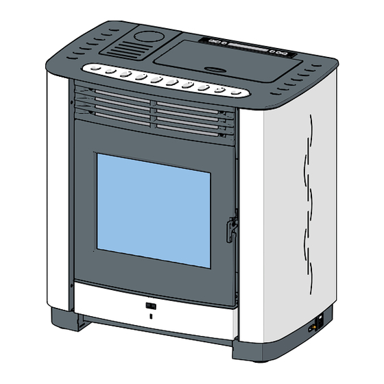
- Page 1 Pellet stove GIOIA INSTRUCTION FOR INSTALLATION, USE AND MAINTENANCE...
- Page 2 Dear Customer, Thank you for having chosen one of our products, which is the result of years of experience and continuous research aimed at making a superior product in terms of safety, reliability and performance. This booklet contains information and advice for safe and efficient use of your product.
-
Page 3: Table Of Contents
CONTENTS DT2010187-00 Section Heading Page GENERAL RULES Single chimney or flueway Soot inspection Chimney stack Fresh air intake Installation enviroment Load-bearing capacity of the floor Heating capacity Flueway Connecting to a conventional chimney 1.10 Using an external flue 1.11 Prevention of domestic fires 1.12 Minimum safety distances FEATURES AND TECHNICAL DATA Features... -
Page 4: General Rules
1.0 GENERAL RULES DT2010216-05 Ensure that the installation of your product conforms to all the indications given below. Fig. 1 CHIMNEY STACK CHIMNEY CONNECTION TO FLUE FLUEWAY SOOT INSPECTION APERTURE FRESH AIR INTAKE ELECTRIC POWER SUPPLY CAPACITY LOAD OF THE FLOOR MINIMUM SAFETY DISTANCES DT2030321-01... -
Page 5: Single Chimney Or Flueway
DT2010024-02 1.1 SINGLE ChIMNEy OR FLUEwAy Every appliance must have a vertical flue pipe operating by natural Fig. 2 draught to discharge the combustion gases outdoors. The flue must: - Comply with regulations in force in the place of installation of the appliance. -
Page 6: Chimney Stack
DT2010025-03 1.3 ChIMNEy STACk The chimney stack is a device fitted on the top of the chimney that is designed to Fig. 7 Fig. 8 aid dispersion of the products of combustion in the atmosphere. The chimney stack must comply with the following requirements: - It must have an internal section and shape the same as the flue (A). -
Page 7: Fresh Air Intake
DT2010539-03 1.4 FRESh AIR INTAkE To ensure trouble-free operation the stove/firebox must have the Fig. 12 Fig. 13 necessary air available for combustion and this is provided through the fresh air intake. The fresh air intake must: - Have a total free cross section at least equal to the size given in the paragraph “TECHNICAL DATA”. -
Page 8: Load-Bearing Capacity Of The Floor
Gas appliances of type B are not allowed (refer to current legislation and regulations in the place of installation). The firebox must not be used simultaneously with collective type ventilation ducts with or without extractor fan, other devices or other appliances such as: forced ventilation systems or other heating systems using ventilation to change the air. Such systems could cause a vacuum in the environment of installation even if installed in adjoining or communicating rooms. -
Page 9: Flueway
4,5 m + 1 m + 1 m = 6,5 m. Where 100 mm diameter pipe must be used, connect it to the stove flue outlet with a 80mm union-tee then use a 80 mm 100 mm adaptor (not supplied by Superior) (Fig. 16). H072058UK0 / DT2001650 – 00... -
Page 10: Connecting To A Conventional Chimney
INSULATING periodic cleaning of the flue without the need to disassemble the pipes. MATERIAL This type of fitting can be bought at Superior retail outlets together with the pipes. An example is given below of a flueway connection, which allows complete cleaning without having to disassemble the pipes (Fig. -
Page 11: Using An External Flue
• Check that the connection to the flueway is gas/smoke-tight, since Fig. 19 the appliance operates in a vacuum. CLOSING FLANGE • Check that the pipe does not penetrate too far into the flueway, thereby choking the pipe for the passage of smoke and combustion gases. Ensure that all installation work is carried out to professional standards. -
Page 12: Prevention Of Domestic Fires
DT2010027-02 1.11 PREvENTION OF dOMESTIC FIRES The product must be installed and used in compliance with the manufacturer’s instructions and European and national standards as well as local regulations. When a flue pipe passes through a wall or a ceiling, special installation methods must be applied (protection, thermal insulation, distances from heat-sensitive materials, etc.). -
Page 13: Features And Technical Data
Timer thermostat: ....standard with daily, weekly and weekend programming modes divided into two time bands Power setting: ......from 1 to 4 Ash drawer: ......removable Fuel: ........natural pure wood pellets (see “FUEL” section) Heating: ........forced ventilation DT2012743-01 2.2 TEChNICAL dATA GIOIA Unit of Measurement at rated power at minimum power Thermal power Hourly consumption kg/h Performance 86.6... -
Page 14: Accessories And Equipment
DT2011648-00 2.3 ACCESSORIES ANd EqUIPMENT Description Room sensor NTC 10K provided Cable L=200 Schuko IEC provided Pellet stove door handle tool provided Grate baffle plate provided Silicone paint spray can optional Humidifier optional Side flue gas outlet kit optional Remote control kit optional Pipes and elbows for connection to the flueway optional... -
Page 15: Dimensions
DT2034321-00 2.5 dIMENSIONS Measurements in cm. A = Smoke outlet diameter 8 cm H072058UK0 / DT2001650 – 00... -
Page 16: Preparing For Installation
Pursuant to current regulations on the safety of electrical equipment, Fig. 27 you must contact a Superior After-Sales Service Centre or a qualified electrician for all and any work connected with installation, maintenance or servicing that involves access to electrical parts. -
Page 17: Electrical Connection And Controls
DT2011601-01 4.1 ELECTRICAL CONNECTION ANd CONTROLS Power cable (6) Fig. 28 • The stove/firebox comes with a power cable which must be connected to a 230V/50Hz mains socket. Connection to the rear of the stove/ firebox is shown in fig. 28. •... -
Page 18: Removing The Cladding
DT2011600-00 4.3 REMOvING ThE CLAddING If work has to be carried out inside the cladding, the side panels must Fig. 31 be removed as follows: - Remove the upper grille (A) after unscrewing the 4 fastening screws (B). (Fig. 31) - Remove the 2 screws (C) that secure the lower front panel (D), lift it Fig. -
Page 19: Upper Smoke Outlet
DT2012748-00 4.4 UPPER SMOkE OUTLET This product is supplied with the smoke outlet at the back. Fig. 35 It is however possible to choose to have the outlet on the top of the stove as follows: - Remove the left side panel (see the section “REMOVING THE CLADDING”). -
Page 20: Fuel
Pellet characteristics This “customisation” of stove settings must be carried out at Components natural pure wood pellet a Superior Service Centre or by specially qualified personnel Length, approx. 10 – 30 mm authorised by the factory. Diameter, approx. -
Page 21: Loading The Pellets
DT2010730-01 5.1 LOAdING ThE PELLETS • In order to load pellets into the tank, we recommend removing the Fig. 38 Fig. 39 bag flap opening and emptying it into the tank. This way, the loading operation is easier and you avoid spilling the pellets over the appliance. Do not allow the build-up of residue at the bottom of the tank. -
Page 22: Control Panel
DT2011650-01 6.1 CONTROL PANEL - The stove features a digital control panel that allows the user to control all of the functions. - The display shows the current time (e.g. 12:30) or room temperature and the OFF message when the stove is connected to the electrical main but is not on. -
Page 23: Programming
DT2011652-01 6.3 PROGRAMMING Pressing button 6 for at least 5 seconds accesses the stove programming mode. Press buttons 5 and 6 repeatedly to scroll through the main menu on the display. Pressing button 4 again returns to the previous menu. After selecting the function to set, confirm it by pressing the SET button and proceed to sub-menu settings with buttons 1 and 2. -
Page 24: Setting The Clock
DT2011643-02 6.4 SETTING ThE CLOCk The correct time setting is required for the use of all time-dependant functions. The clock allows programming of the following values: days, hours and minutes. These values are displayed sequentially by pressing the SET button. Activity description Display message Press button 6 for a few seconds... -
Page 25: Thermostat
DT2011653-01 6.5 ThERMOSTAT The function of the thermostat is to allow the user to program the stove so that it is switched on and off independently without the manual intervention of an operator. This thermostat allows you to select the daily, weekly and weekend programs with a maximum of 2 cycles in two different time slots. For example: cycle: from 06.00h to 09.00h. - Page 26 Activity description Display message 25° set temp Press buttons 1 and/or 2 to set the room temperature for the first work cycle. Confirm by pressing SET. room 1 The thermostat automatically advances to programming of the second work cycle. If you want to continue with the programming of the second cycle, proceed in sequence 17:20 start D...
- Page 27 PROGRAM WEEK-END DT2011656-01 Activity description Display message Press button 6 for a few seconds Scroll through the menu that appears on the display with buttons 5 and 6 until the option SET CHRONO appears. CHRONO Confirm by pressing SET. Scroll through the functions on the display until with buttons 5 and 6 reaching option program week-end PROGRAM WEEK-END.
-
Page 28: Menu Parameter
DT2011676-01 6.6 MENU PARAMETER Within the parameter menu the user will be able to interact only with the MEMORY COUNTERS menu as described in the table below: all other items are for the sole use of the authorised technical support centre. MEMORY COUNTER DT2011679-00 Activity description... -
Page 29: Display Sleep Mode
DT2012615-00 6.8 dISPLAy SLEEP MOdE The function DISPLAY SLEEP MODE is used to set display switch off if the key panel remains idle for over 1 minute. Activity description Display message Press button 6 for a few seconds Use the s and/or 6 buttons to select the DISPLAY DISPLAY SLEEP MODE SLEEP MODE menu. -
Page 30: First Start-Up
Activity description Display message The stove enters the stop phase upon reaching 3 temperature set in the STOP function. ENERGY OK The display shows the message "ENERGY OK". If the stove is switched off with the ENERGY SAVING function set, the display shows OFF E the message OFF E. - Page 31 Activity description Display message START PHASE I The smoke aspirator is activated. The auger is engaged and begins to convey pellets to the brazier. - If during the start-up phase, the exit smoke probe detects rising temperature (indicating a combustion process), the device is considered on and thus passes to the normal operating mode.
- Page 32 Activity description Display message If the tank has completely depleted the pellet supply while running and the smoke temperature decreases, the message E7 is shown on the display (the alarm beep is activated). The stove reverts to alarm mode. WHAT TO DO - Press the button 4 to shut the stove down.
- Page 33 NORMAL FUNCTIONING DT2011662-01 Activity description Display message The stove goes into steady normal functioning if the start cycle was successful. The display shows the power level set: P1, P2, P3, P4. 12:50 The display shows the time or the room temperature (see section “MODE DISPLAY”). The power and room temperature can be adjusted during normal functioning.
- Page 34 SHUT DOWN DT2012622-00 Activity description Display message Press and briefly hold the button 4. SHUT DOWN Pellet loading is interrupted, while the room air fan and smoke exit continue to run, until the appliance is cooled. The appliance shuts off. WAIT COOLING See the “EMPTY BRAZIER”...
- Page 35 POWER SUPPLY FAILURE DT2012623-01 Activity description Display message The power supply may fail during stove operation. It is necessary to distinguish between: 1) power failure during START PHASE I or START PHASE II; 2) power failure without chrono settings; 3) power failure with chrono settings. Power failure during START PHASE I or START PHASE II.
-
Page 36: Safety Devices
EMERGENCY ON DT2040098-00 Activity description Display message The stove can be started manually if the ignition spark fails to work by following this procedure: - load a small quantity of pellet into the brazier; - start a fire using a fragment of solid fire starter (not liquid); - close the door;... - Page 37 SMOKE BOX DEPRESSION DT2012624-00 Activity description Display message The pressure switch is connected in the smoke flue and has the function to control the vacuum inside the flue allowing the use of the appliance in total safety. The pressure switch is activated if the flue evacuation conditions are altered (bad installation, obstacles or impediments in the flue, negligent maintenance, adverse weather conditions such as persistent wind etc..).
- Page 38 SMOKE TEMPERATURE PROBE DT2012626-00 Activity description Display message The smoke probe is connected to the electronic board and constantly measures operating temperature, allowing the appliance to be used in total safety. If the temperature exceeds the safety threshold, the board isolates the supply voltage to the auger, thus stopping pellet feed to the brazier, followed by engaged appliance shut down.
- Page 39 UNPROGRAMMED STOP DT2012655-00 Activity description Display message - The message E7 is shown on the display. This means that smoke temperature falls below the minimum operating temperature when the stove is operating. - The alarm beep sounds. WHAT TO DO - Press and briefly hold the button 4 to deactivate the appliance.
-
Page 40: State Stove
DT2012629-00 6.13 STATE STOvE This function shows stove state during the various operating conditions. Activity description Display message Press button 6 for a few seconds Scroll through the menu that appears on the display with buttons 5 and 6 until the STATE STOVE option STATE STOVE appears. -
Page 41: Humidifier (Optional)
DT2011671-00 6.16 hUMIdIFIER (OPTIONAL) The stove is provided with a niche for a humidifier (optional) located Fig. 43 under the ceramic insert of the top plate: once the ceramic cladding has been fitted, the humidifier can be filled with water. When refilling the humidifier do not exceed the maximum capacity, shown as max, otherwise the electrical parts of the stove could be damaged. -
Page 42: Maintenance
DT2011672-00 Pursuant to current regulations on the safety of electrical equipment, you must contact a Superior After-Sales Service Centre or a qualified electrician for all and any work connected with installation, maintenance or servicing that involves access to electrical parts. -
Page 43: Cleaning The Ash Tray
DT2010100-03 7.2 CLEANING ThE ASh TRAy Daily, check the ash drawer to see if it needs emptying. Fig. 46 To dispose of the ashes, refer to the paragraph “DISPOSAL OF ASHES”. This type of cleaning requires a vacuum cleaner suitable for holding ash. -
Page 44: Cleaning The Smoke Chamber
DT2011674-00 7.4 CLEANING ThE SMOkE ChAMbER Clean the smoke chamber every three months as follows: Fig. 49 - remove the left side panel (see the section “REMOVING THE CLADDING”). - remove the lower left casing (A) by removing the four screws which secure it;... -
Page 45: Cleaning The Enamelled Metal Parts
The door of the stove is equipped with a ceramic glass window 4 mm thick, resistant to temperatures up to 750°C; the glass can only be broken by a strong blow or improper use. Do not slam the door or hit the glass. Should the glass break, only replace it with a spare part from the Superior factory. Proceed as follows to replace the glass: - Equip yourself with an appropriate pair of protective gloves. -
Page 46: Cleaning The Fans
Any build-up of dust or ash on the blades can unbalance them resulting in noise during operation. It is necessary to have the fans cleaned annually. Since such an operation involves dismantling certain parts of the stove, have the cleaning carried out only by a Superior Service Centre or other qualified persons. DT2011801-00 7.12 ShUTTING dOwN... -
Page 47: Replacing The Fuses
DT2010557-02 7.14 REPLACING ThE FUSES Electronic board fuse. Fig. 51 Unscrew the cartridge fuse or safety plug (A) from the electronic board and replace with a similar one. Motherboard fuse type: F4AL250V DT2032439-00 Fuse on the IEC power socket. Fig. 52 Draw out the fuse carrier and replace the fuse with the spare to be found inside the small drawer (B). -
Page 48: Main Anomalies
8.0 MAIN ANOMALIES (In grey the user operations) DT2012630-01 Some of the anomalies below can be resolved by following the instructions. All operations must be carried out when the appliance is cold and in the absence of electrical power (pull the plug). As pursuant to law, qualified personnel must resolve anomalies or make repairs that require work to be performed on the components inside the cladding or combustion chamber. - Page 49 Problem Cause Solution Evacuation system obstructed Clean the smoke evacuation system Faulty electronic board. Replace the electronic board (use only original parts). Threshold temperature probe is faulty Replace the control probe (use only original parts). THRESHOLD TEMPERATURE Check the proper position of the probe in its seat (see wiring Incorrect position of the smoke probe.
-
Page 50: Standards And Laws Of Reference
STANDARDS AND LAWS OF REFERENCE DT2010209-05 EN 14785 ....Residential space heating appliances fired by wood pellets – Requirements and test methods CEI EN 60335-1 ....Household and similar electrical appliances - Safety. Part 1: General requirements CEI EN 60335-2-102 . - Page 52 Product serial number, to be quoted when requesting service from the After-Sales Service Centre. Via Montello, 22 31011 Casella d’Asolo (TV) - ITALY Tel. +39.04235271 - Fax +39.042355178 www.superiorstufe.com e-mail:info@superiorstufe.com...
Need help?
Do you have a question about the GIOIA and is the answer not in the manual?
Questions and answers