Wilo Helix VE 22 Series Installation And Operating Instructions Manual
Hide thumbs
Also See for Helix VE 22 Series:
- Installation and operating instructions manual (198 pages)
Advertisement
Quick Links
Advertisement

Related Manuals for Wilo Helix VE 22 Series


Summary of Contents for Wilo Helix VE 22 Series
- Page 1 Pioneering for You Wilo-Helix VE 22..., 36..., 52... de Einbau- und Betriebsanleitung Inbouw- en bedieningsvoorschriften en Installation and operating instructions ru Инструкция по монтажу и эксплуатации Notice de montage et de mise en service 4 151 995-Ed.05 / 2015-09-Wilo...
- Page 2 Fig. 1...
- Page 3 Fig. 2...
- Page 4 Fig. 3 Fig. 6 Fig. 7...
- Page 5 Fig. 4 -2 -3 (mm) Type PN16/PN25/ Helix VE22 130 296 215 250 300 90 DN50 125 4 x M16 PN30 PN16 4 x M16 Helix VE36 250 320 105 DN65 145 16 x PN25/PN30 8 x M16 Ø14 PN16/PN25/ Helix VE52 250 365 140 DN80 160 8 x M16 PN30...
- Page 6 Fig. 8...
- Page 7 Fig. A1...
- Page 8 Fig. A2 Fig. A4 Fig. A3...
- Page 9 It draws attention to possible problems. led away so that no danger to persons or to the Information that appears directly on the product, environment arises. National statutory provisions such as are to be complied with. WILO SE 01/2016...
-
Page 10: Intended Use
(humidity, frost etc.). The product should be cleaned thoroughly before it is put into temporary storage. The product can be stored for at least one year. Handle the pump carefully to avoid any damage prior to installation. WILO SE 01/2016... -
Page 11: Technical Data
K = Cartridge seal, versions without “K” are equipped with simple mechanical seal S = Lantern orientation align with suction pipe Bareshaft pump (without motor) Motor frequency ( Hz) Ø motor shaft – 38FF265 lantern size xxxx Options code (if any) WILO SE 01/2016... - Page 12 (< 1 m from the electronic module) of radio transmission installations, transmitters or similar devices working in this frequency range. The function of the pump is not affected at any time. WILO SE 01/2016...
-
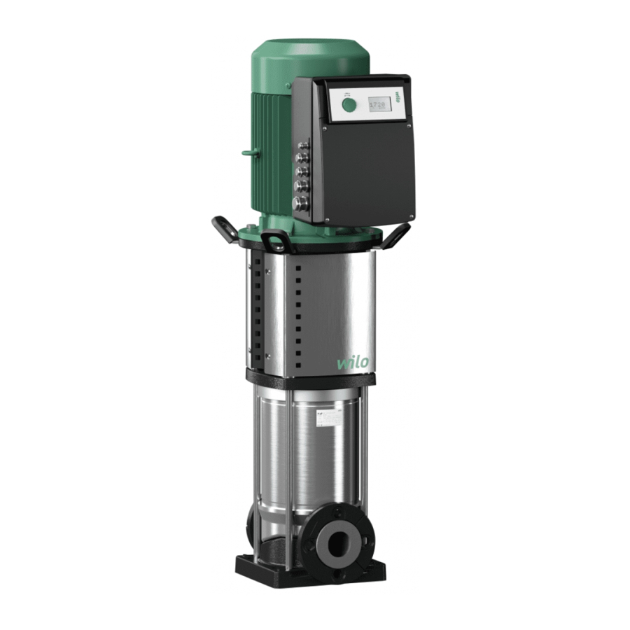
Page 13: Description And Function
3 – Cartridge seal 4 – Hydraulic stage housing 5 – Impeller 6 – Pump shaft 7 – Motor 8 – Coupling 9 – Lantern 10 – Tube liner 11 – Flange 12 – Pump casing 13 – Base plate WILO SE 01/2016... -
Page 14: Installation And Electrical Connection
IP55 protection. If used in CAUTION! Risk of damage to the pump! air-conditioning or cooling systems, remove these Contamination and solder residue in to the pump plugs to allow draining. body may affect pump operation. WILO SE 01/2016... - Page 15 Tightening of screws or bolts must not exceed: Wilo catalogue. Configuration PN16 / PN25 NOTE: Motor ower can be adjusted in accordance with the fluid’s characteristics. Contact the Wilo M10 – 20 N.m M12 – 30 N.m customer service, if required.
- Page 16 [Ext.off] and [Aux] must be shielded. Power (kW) 0.55 0.75 Cable, shielded Power (kW) The metal threaded cable connections of the converter are prepared for the connection of braided shielding. Power (kW) 18.5 Cable, shielded 1xM32/40 1xM20 1xM16 2xM12 WILO SE 01/2016...
- Page 17 As soon as the power supply to the electronic mod- ule is established, a 2-second display test is carried out during which all characters on the display are shown. WILO SE 01/2016...
- Page 18 The connection is twist-proof. NOTE: Terminals IN1,IN2, GND and Ext. Off meet the requi- rements for „safe isolation“ (in acc. with EN61800-5-1) at the mains terminals as well as at SBM and SSM terminals (and vice versa). WILO SE 01/2016...
- Page 19 • The remote control allows the pump to be switched On Example: Float switch, pressure gauge for dry-running, and Off (free contact), this function has priority over other etc. functions. • The remote control can be removed by bridging the termi- nals (3 and 4). WILO SE 01/2016...
- Page 20 20mA/10 • 2 wires ([20 mA/10 V]/+24 V) 10 11 • 3 wires ([20 mA/10 V] / 0 V/+24 V) and setpoint setting by external set value Remote External pressure control set value sensor Auxiliary control WILO SE 01/2016...
- Page 21 Input voltage (V) Sensor signal 0 – 20 mA Sensor signal 2 – 10 V 100% 100% Value Value in % of the sensor in % of the sensor measurement range measurement range Input current (mA) Input voltage (V) WILO SE 01/2016...
- Page 22 External signal 4 – 20 mA External signal 2 – 10 V 100% 100% Converter stopping range Converter stopping range Safety Safety Frequency range Frequency range of converter of converter ~30% ~30% Input current (mA) Input voltage (V) WILO SE 01/2016...
- Page 23 If the pumped fluid is hot and under high pressure, the liquid escaping at the venting plug may cause burns or other injuries. - Fully open the guard valve on the discharge side (3). - Close the drain plug (5a). WILO SE 01/2016...
- Page 24 • Turn the rotary knob to scroll through any menu level (e.g. 4000 -> 5000). • Blinking elements (value, menu number, symbol or icon) allow the selection of a new value, a new menu number or a new function. WILO SE 01/2016...
- Page 25 P.I.D control. <3.0.0.0> Position Switch 1 Description OPERATION Setting the pump ON/ OFF. SERVICE <4.0.0.0> Position Switch 1 Description OPERATION Read-only display of the „Information“ menu. SERVICE • Menu „Information“ displays measuring, device and operating data (Fig. A6). WILO SE 01/2016...
- Page 26 English Fig. A5 Navigation in basic menus in normal operation (Switch 1 = OFF in „OPERATION“ position) Setpoint Control type Pump Information Service Fault acknowledgement Appears when a fault is triggered WILO SE 01/2016...
- Page 27 Power Operating data Operating hours Consumption Power-on counter Actual conditions SSM relay See section 10 – Menu <5.6.7.0> SBM relay Default “Available transfer” Ext. off Device data Pump name User controller software version Motor controller software version WILO SE 01/2016...
- Page 28 • „Speed control“ • „Constant pressure“/“Variable pressure“ • „P.I.D. control“ Then, in menu <5.0.0.0>, the Expert Mode provides access to all converter parameters (Fig. A9). • After setting, set switch 1 to the OFF position (Fig. A1, Pos. 1). WILO SE 01/2016...
- Page 29 External setpoint input – IN2 Selection of signal type Parameterisation P.I.D. Selection value „P“ (0.0-300.0) Parameterisation P.I.D. Selection value „I“ (10 ms – 300 s) With external setpoint Parameterisation P.I.D. Selection value „D“ (0 ms – 300 s) WILO SE 01/2016...
- Page 30 Selection parameters „P“ Selection parameters „I“ Selection parameters „D“ Other settings Only displayed when Zero flow delay „Constant Pressure“ or „Variable period Pressure“ is enabled Selection of reduced frequency Selection of SBM relay Factory settings WILO SE 01/2016...
-
Page 31: Maintenance
• For starting up, we recommend a pressure set value of 60 % of the maximum pressure. „P.I.D. control“ mode Control by a sensor (temperature, flow rate, etc.) by P.I.D. control and setpoint (internal or exter- nal). WILO SE 01/2016... -
Page 32: Faults, Causes And Remedies
The non-return valve is not adequate Replace it by an adequate non-return valve Low tank capacity due to installation Change it or add a tank to the installation If the fault cannot be resolved, please contact the Wilo customer service. WILO SE 01/2016... - Page 33 (until manual inter- vention). Example: 6 defects with a variable time limit within Faults 24 hours. State of SBM relay is „Available transfer“. Active relay Relay in relay Active relay Relay in relay 24-hour period WILO SE 01/2016...
- Page 34 Immediately Immediately No restart Inrush-current relay defective Contact after-sales technician 60 s E076 Immediately Immediately No restart Current sensor defective Contact after-sales technician 60 s Power E099 Immediately Immediately No restar Unknown pump type Contact after-sales technician off/on WILO SE 01/2016...
- Page 35 NOTE: If time for the resolution of the defect remains after the fault signal (e.g. 300 s), then the fault must always be acknowledged manually. The auto reset timer is inactive and „- - -“ is displayed. WILO SE 01/2016...
-
Page 36: Spare Parts
NOTE: The pump must not be disposed of along with household waste. Further information on recy- cling can be found at www.wilo-recycling.com. Subject to change without prior notice. WILO SE 01/2016... - Page 38 Bombas Wilo-Salmson WILOIbéricaS.A. Vietnam ZIPCode:13.213-105 Burton Upon Trent WILOPumpsLtd. PortugalLda. 28806AlcaládeHenares WILOVietnamCoLtd. T +55 11 2923 (WILO) DE14 2WJ 618-220Gangseo,Busan 4050-040 Porto (Madrid) HoChiMinhCity,Vietnam T +44 1283 523000 T +82 51 950 8000 T +351 22 2080350 T +34 91 8797100...
- Page 39 WILO SE Nortkirchenstraße 100 D-44263 Dortmund Germany T +49(0)231 4102-0 F +49(0)231 4102-7363 wilo@wilo.com Pioneering for You www.wilo.com...
Need help?
Do you have a question about the Helix VE 22 Series and is the answer not in the manual?
Questions and answers