Table of Contents

Related Manuals for Staco Energy FirstLine


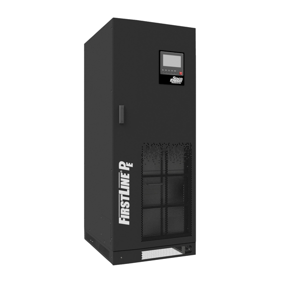
Summary of Contents for Staco Energy FirstLine
- Page 1 The FIRSTLINE UPS 25KVA, 30KVA, AND 37.5KVA User’s Manual 301 Gaddis Boulevard • Dayton, Ohio 45403 U.S. Toll Free 866-261-1191 (937) 253-1191 • Fax: (937) 253-1723 Web site: www.stacoenergy.com Form No.003-2323 Rev B 09/04/2009...
- Page 2 Before Installing the UPS: -Read all safety and installation instructions. -Make sure that the UPS is the correct model for your application. -Verify that the available power source matches the input rating of the UPS. Unless the UPS is in the tall cabinet and is equipped with a transformer option, the source should be 120 volts line to neutral, three phase, ABC sequence, with a grounded neutral.
-
Page 3: Table Of Contents
Stopping the Rectifier in the UPS ................... 33 UPS Maintenance ......................34 Battery Fuse Replacement ..................... 35 Section 9 ..........................37 Optional FirstLine Extended Run Time Battery Cabinet ..........37 Section 10 .......................... 38 FirstLine UPS Technical Specifications ................38 Form No. 003-2323 Rev B... - Page 4 Figure 11-Communication Options and Control Terminals ..........20 Figure 12-TB3 ........................21 Figure 13-TB4 ........................21 Figure 14-FirstLine Front Panel Display and Control Module ..........22 Figure 15-Battery Tray ....................... 29 Figure 16-Battery Tray ....................... 30 Figure 17-Battery Installation ..................... 31 Figure 18-The FirstLine Extended Run Time Battery Cabinet ..........
-
Page 5: Section 1
SECTION 1 Introduction The FirstLine uninterruptible power supply (UPS) is a true online, double-conversion, three- phase system that can be used to prevent loss of valuable electronic information and minimize equipment downtime. It is ideal for protecting essential information technology and electrical engineering infrastructure in corporate, telecom, health care, banking, and industrial applications. -
Page 6: Firstline Ups Part Number System
FirstLine UPS FirstLine UPS Part Number System Table 1-Part Numbering System Full Part Number Output Basic Part Battery Other Input Voltage Time Cabinet Voltage Option Options (min.) 208Y/120 208Y/120 Short FLU-25S-20 -1 208Y/120 Tall FLU-25T-42 -1 480Y/277 Tall FLU-25T-44 -1... -
Page 7: Accessories
FirstLine Extended Run Time Battery Cabinets can be used with each UPS. The cabinet is styled to match the FirstLine UPS. The battery cabinet can be ordered with an optional disconnect switch or a user provided disconnect arrangement can be used. -
Page 8: Section 2
FirstLine UPS SECTION 2 Safety Warnings IMPORTANT SAFETY INSTRUCTIONS SAVE THESE INSTRUCTIONS This manual contains important instructions that you should follow during installation and maintenance of the UPS and batteries. Please read all instructions before operating the equipment and save this manual for future reference. - Page 9 FirstLine UPS DANGER This UPS contains LETHAL VOLTAGES. All repairs and service should be performed by AUTHORIZED SERVICE PERSONNEL ONLY. There are NO USER SERVICEABLE PARTS inside the UPS. WARNING This UPS contains its own energy source (batteries). The UPS output may carry live voltage even when the UPS is not connected to an AC supply.
-
Page 10: Section 3
480 I/O 1855 Lbs (841 kg) 590 lb/in (42 kg/cm2) Clearances The following clearances are recommended for the FirstLine UPS. 36” (91.4 cm) working space From Front of Cabinet 12” (30.5 cm) From Back of Cabinet Minimum 24” (61 cm) From Side of Cabinet Form No. -
Page 11: Unloading The Cabinet(S)
FirstLine UPS Unloading the Cabinet(s) The following tools are required for unloading the cabinet(s): Wrenches for 1/4” bolts and 1/2” nut Forklift CAUTION The UPS and optional cabinets are heavy (see Table 3). Unloading the cabinets requires at least two people to safely remove the cabinets from the pallet. -
Page 12: Figure 3-Shipping Bracket
FirstLine UPS Remove and discard 1/4" bolt and washers (4) places Remove (4) 1/4" bolts. Reinstall after the unit is on the floor Pull (2) shipping brackets away from cabinet. Loosen (3) 1/2" nuts on each bracket Remove (4) 1/4" bolts. -
Page 13: Figure 4-Lifting Fork Area
FirstLine UPS 13.00" [330mm] Max. Place forks in this area Leveling foot so as not to damage the leveling feet or casters. Set forks to a maximum 13 inches at outside width. Figure 4-Lifting fork area Form No. 003-2323 Rev B... -
Page 14: Placing The Cabinet
FirstLine UPS Placing The Cabinet Once the cabinet has been rolled into position, remove the front panel to access the front leveling feet by pulling the panel outward at the bottom of the unit until it unsnaps and then lift up and off the cabinet (see figure 9). Adjust the leveling feet as shown in figure 5. -
Page 15: Section 4
FirstLine UPS SECTION 4 Electrical Installation The FirstLine has the following power connections: 3-phase (L1, L2, andL3), neutral, and ground connection for rectifier/bypass input 3-phase (L1, L2, and L3), neutral, and ground connection for load output The input neutral connection is not used when the UPS is equipped with the optional isolation transformer. -
Page 16: Figure 6-Bottom View
FirstLine UPS Switch off utility power to the distribution point where the UPS will be connected. Be absolutely sure there is no power. Determine your equipment’s grounding requirements according to your local electrical code. Remove the UPS rear panel. Conduit landing plates are located at the rear bottom of the base to accommodate bottom wire entry to the cabinet (see figure 6). -
Page 17: Wiring Installation
FirstLine UPS Wiring Installation Unscrew and remove the rear panel. Connect the input wires to the proper terminals shown in Figure 7. Insure proper phase rotation. Input neutral is not required if the UPS is equipped with an optional input isolation transformer. - Page 18 FirstLine UPS Table 6-FirstLine UPS 25-37.5 kVA Current Requirements Input Input Max. Input Maximum Rating Voltage Transformer Current (A) Allowable Branch Option Allowed for Circuit Protection Specified Branch Protector 25 kVA 208 V None 25 kVA 208 V Isolation 25 kVA...
-
Page 19: Wiring Specifications And Diagrams
FirstLine UPS Wiring Specifications and Diagrams Note: Input neutral must be wired for proper operation or the UPS will not start. Note: Do not over-tighten the screws; be sure to use the specified tightening torque values shown in Table 4, Table 5, and Table... -
Page 20: Table 7-Terminal Block Wiring
FirstLine UPS Table 7-Terminal Block Wiring Voltage Input Phase Neutral Neutral Conductor with Ground Wire Rating Transformer Conductor Conductor non-linear loads Min/Max Type Min/Max Min/Max Min/Max 25kva 208/120 NA #2/2-0 #2/2-0 #2/2-0 #8/1-0 208 isolation #2/2-0 (none) (none) #8/1-0 220/127 NA... -
Page 21: Figure 8-Ups Wiring-Single Line Diagram
FirstLine UPS Per NEC article 300-20(2), all three-phase conductors must be run in the same conduit. Neutral and ground must be run in the same conduit as the phase conductors. Conduit to be sized to accommodate one neutral conductor the same size as the phase conductor and one ground conductor. -
Page 22: Removing And Replacing The Front Panel
FirstLine UPS Removing and Replacing The Front Panel Pull the top of the panel outward until the ball studs unsnap. Lift the panel up and off the cabinet. To replace the panel: Lower the shoulder screws at the top of the panel into the keyhole slots on the cabinet. -
Page 23: Figure 10-Internal Battery
If an Extended Battery Cabinet is to be connected, do so at this time. Refer to the User’s manual for the FirstLine Extended Run Time Battery Cabinet. Also, refer to the special notes in Section 8 of this manual. -
Page 24: Section 5
FirstLine UPS SECTION 5 Communication Figure 11 shows the location of the communication options and terminals on the UPS. TB2 Contact sensing inputs TB3 Form C contact outputs terminal block terminal block TB1 REPO/Bypass terminal block TB4 Opto-isolated outputs 9 10... -
Page 25: Table 8-Torque Values For Tb1, 2, 3, 4
FirstLine UPS There are five sets of form-C dry contact available as outputs. They are capable of switching up to 30 volts (AC or DC) at up to 1 amp. Listed in order of NO, COM, NC. TB3 terminals 1, 2, 3 – running on inverter. -
Page 26: Section 6
FirstLine UPS SECTION 6 Operation This SECTION contains information on how to use the FirstLine UPS, including front panel operation, UPS startup and shutdown. Control Panel Functions The UPS has LCD with backlight. It provides useful information about the UPS itself, load status, events, measurements, and setting (see figure 14). -
Page 27: Table 9-Indicator Status And Description
FirstLine UPS The following table shows the indicator status and description: Indicator Status Description Bypass Bypass input voltage or frequency not qualified Bypass Green Bypass input voltage or frequency qualified Bypass Yellow Inverter output not synchronized to bypass input Bypass... -
Page 28: Display Functions
Display Functions As the default or after 15 minutes of inactivity, the LCD displays the selectable startup screen. The default is the Staco Energy Products Co. logo and can be changed to the Mimic screen in the User Settings menu. -
Page 29: Section 7
FirstLine UPS SECTION 7 Initial Start Up To be performed by authorized service personnel. Inspect for damage. Remove front cover panel, inner front access panel, front shipping support panel, top cover, and rear panel. Look for signs of damage due to handling including bent supports, loose components, etc. -
Page 30: Manual Transfer To Bypass
FirstLine UPS Manual Transfer to Bypass Verify that the bypass input is qualified by observing that the bypass indicator is green. While holding down the ESC key, press the up-arrow key. When the conditions are met for a transfer to bypass (bypass input is qualified and inverter is synchronized to bypass), the static switch will transfer the load to bypass. -
Page 31: Automatic Transfer To Bypass
FirstLine UPS Automatic Transfer To Bypass The static switch will automatically transfer the load to bypass if the bypass input is qualified and one of the following conditions applies: Initial start-up of UPS. The inverter is unable to support the load due to a) failure, b) overload, c) battery reaches end of discharge voltage threshold. -
Page 32: Overload
FirstLine UPS OverLoad Inverter Load Time Supported 100% Continuous 110% 2 Minutes 125% 30 Seconds When the overload limits are exceeded while running on inverter, an automatic transfer to bypass occurs. When the overload clears, an automatic transfer to inverter occurs, unless there have been three overloads within one hour. -
Page 33: Section 8
FirstLine UPS SECTION 8 Battery Removal, Installation, and Service The batteries must only be serviced by authorized service personnel. Before any battery service is attempted, the batteries must be disconnected by unplugging the cables to the battery trays. Before unplugging the cables, the connections should be marked in a way that no confusion will exist when it is time to reconnect the cables. -
Page 34: Figure 16-Battery Tray
FirstLine UPS If the trays are to be removed, always remove the highest tray first. The battery trays are very heavy and it will be necessary to use a lifting device to support the trays as they are removed. When the trays are to be reinstalled, use the procedure in the following paragraph. -
Page 35: Figure 17-Battery Installation
FirstLine UPS 1/4-20 Ground terminal stud Tray mounting screw Battery tray assemblies Figure 17-Battery Installation EXTENDED RUN TIME BATTERY TERMINAL TIGHTENING TORQUE #2-#3 AWG 50 inch-pounds #4-#6 AWG 45 inch-pounds Note: Size wire per local codes, #6 AWG 75°C copper wire minimum to #2 AWG maximum. -
Page 36: Polarity Verification Procedure
FirstLine UPS Special Considerations for Connection Batteries to the FirstLine UPS, including Extended Run Time Battery Cabinets It is never safe to work within either the UPS or the extended battery cabinet while the UPS is powered. The battery produces a lethal voltage whether or not the UPS is powered or running. -
Page 37: Stopping The Rectifier In The Ups
FirstLine UPS If the UPS has an internal battery, connect it to the DC input connector. If there is an external user supplied battery disconnect device, it should be closed. At the external battery cabinet, measure the dc voltage from the left-hand fuse (positive lead of meter) to the right-hand fuse (negative lead of meter). -
Page 38: Ups Maintenance
UPS Maintenance The FirstLine UPS is designed to be virtually user maintenance free, requiring only the occasional wipe with a damp cloth or non-abrasive cleaner. Spare kits are available for the FirstLine UPS series, please contact Staco Energy Products Co. -
Page 39: Battery Fuse Replacement
FirstLine UPS Battery Fuse Replacement If an input line voltage transient well in excess of the UPS rating occurs while the UPS is running on battery, it is possible for the battery fuse to clear open. The symptom of an open battery fuse is the same as a disconnected battery: after the UPS is started, the battery lamp on the mimic display glows red. - Page 40 FirstLine UPS 11. Reconnect the internal battery(s) in the UPS. 12. Replace the inner panel. 13. In there is an external battery, reconnect all of the batteries and replace the inner panel. If there is the optional breaker, simply close the breaker to connect the battery.
-
Page 41: Section 9
SECTION 9 Optional FirstLine Extended Run Time Battery Cabinet The FirstLine extended run time battery cabinet is used in conjunction with the FirstLine uninterruptible power supply (UPS) to prevent loss of valuable electronic information and minimize equipment downtime. During brownouts, blackouts, and other power interruptions, batteries provide emergency power to safeguard operation. -
Page 42: Section 10
FirstLine UPS SECTION 10 FirstLine UPS Technical Specifications UPS Rating kVA/Kw 25/20 30/24 37.5/30 Input Voltage 208Y, 220Y or 480 Three Phase 4 wire plus ground - Optional 3 wire delta ISO available Range +10% -20% From Nominal (-15% For Battery Recharge)
Need help?
Do you have a question about the FirstLine and is the answer not in the manual?
Questions and answers