
Related Manuals for Staco Energy E3


Summary of Contents for Staco Energy E3
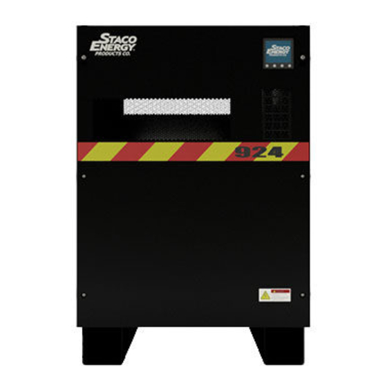
- Page 1 Staco E3 Staco E3 924 Staco E3 PPC 208-600V 50/60Hz 3.5 to 40kVA USER MANUAL 003-2691 REV X0...
- Page 2 No reproduction of any part of this manual, even partial, is permitted without the authorization of Staco Energy Products Company. The Staco Energy Products Company reserves the right to modify the product described herein, in order to improve it, at any time and without notice.
- Page 3 Applicability Distribution Options Rare Options Entry Options Communication Options Bypass Voltage Output Voltage Rectifier Voltage Internal Battery Strings System Code Series (E3: Staco E3 Product Line) Page | iii...
-
Page 4: Safety Warnings
IMPORTANT SAFETY INSTRUCTIONS SAVE THESE INSTRUCTIONS This manual contains important instructions for Models 3.5 - 40kVA Staco E3 series UPS that should be followed during installation and maintenance of the UPS. Please read all instructions before operating the UPS and save this manual for future reference. - Page 5 DANGER This UPS contains LETHAL VOLTAGES. All repairs and service should be performed by AUTHORIZED SERVICE PERSONNEL ONLY. There are NO USER SERVICEABLE PARTS inside the UPS. WARNING To reduce the risk of fire or electric shock, install this UPS in a temperature and humidity controlled, indoor environment, free of conductive contaminants.
-
Page 6: Emergency Interventions
Emergency Interventions The following information is of a general nature. First aid interventions Company regulations and traditional procedures should be followed for any first aid intervention that may be required. Firefighting measures 1. Do not use water to put out a fire, but only fire extinguishers that are suitable for use with electrical and electronic equipment. -
Page 7: Protective Clothing
Protective Equipment No maintenance operations shall be carried out on the unit without wearing the Personal Protective Equipment (PPE) described below. Personnel involved in the installation or maintenance of the unit must be properly clothed. The following signs show the protective equipment that should be worn. The various items of PPE must be selected and sized according to the nature of the hazard (particularly electrical) posed by the unit. -
Page 8: Table Of Contents
Table of Contents Applicability ..............................iii Safety Warnings ............................iv Layout ..............................1 1.1. Views ..............................1 2. Installation ............................... 2 2.1 Important Safety Instructions ......................2 2.1.1 Battery Safety Instructions ......................3 2.2 Equipment Handling .......................... 3 2.2.1 Unpacking and Content Checking ....................3 2.2.2 Storage ............................ - Page 9 6. Maintenance ............................34 6.1 Basic Maintenance Guide ........................ 34 6.1.1 Periodic maintenance (to be carried out by trained personnel and with doors closed) .... 34 6.1.2 Maintenance inside the UPS (factory authorized personnel only) ..........34 6.1.3 Ordinary maintenance for batteries (trained personnel only) ............ 34 6.2 Internal Battery Replacement ......................
-
Page 10: Layout
1. Layout 1.1. Views Figure 1 –Layout Views Page | 1... -
Page 11: Installation
2. Installation Check the Safety Instructions. • Any incorrect connection or handling may cause damage to the UPS and/or the loads • connected to it. Read these instructions carefully and follow the steps indicated. This UPS must be installed by a qualified electrician. •... -
Page 12: Battery Safety Instructions
2.1.1 Battery Safety Instructions WARNING The handling and connection of the batteries shall be done and supervised by personnel with battery knowledge. If an installed a -0 version UPS (no internal battery) and want to install batteries, consult with factory service before attempting to install batteries. Only a qualified technician should attempt to install or replace batteries in this equipment. -
Page 13: Storage
2.2.2 Storage Storage of the UPS should be in a dry, ventilated place and protected against rain, water or chemical agents. It is advisable to maintain the UPS in the original package which has been designed to assure the maximum protection during transport and storage. The UPS may have installed batteries and should not be stored for more than 12 months at 77º... -
Page 14: Power Connections
Figure 2 - Recommended spacing around unit 2.3 Power Connections 2.3.1 Preparing UPS All of the UPS models have terminals for power connection and connectors for communications located inside the UPS front door and rear of unit. Follow the steps described below for access to all connections: Unlock the front door lock with the provided key. -
Page 15: Connection To Mains Input
2.3.2 Connection to Mains Input Connection to the ground: This unit is class I protection against electric shocks, a ground conductor must be installed. Connect the conductor from to the ground, before connecting the power to the UPS input. See 7.2 Rated Currents and Recommend Field Wiring Information for current ratings. Connection to the Input: Connect the power supply cables N-A-B-C to the input power terminals, following the order of neutral and phases indicated on the label of the unit and in this manual. -
Page 16: Connection To The Output
2.3.4 Connection to the Output Connection to the ground: This unit is class I protection against electric shocks, a ground conductor must be installed. Connect the conductor from to the ground terminal before connecting the power to the UPS input. See 7.2 Rated Currents and Recommend Field Wiring Information for current ratings. -
Page 17: External Battery Connection (Ups Or Ul924 Systems Only)
2.3.5 External Battery Connection (UPS OR UL924 systems only) Danger On units with internal batteries, there may be a high level DC voltage across these terminal connections. Use extreme caution when connecting the external batteries. Only use properly insulated tools. Failure to comply may cause irreversible damage to the UPS or personal harm. -
Page 18: Control Connections
2.4 Control Connections 2.4.1 Com Port to Relay The communications line (COM) constitutes a very low safety voltage circuit. To preserve the quality, it must be installed separately from other lines that have dangerous voltages (power distribution line). The communication port to relays provides digital signals in the form of potential free form A contacts. Com Port (see 2.4.2.2 RS-485) connections can be used for connecting the UPS with any machine or units that has standard bus (connector DB9). -
Page 19: Com Port Rs-232 & Rs-485. Connector (J8)
2.4.2 COM port RS-232 & RS-485. Connector (J8). The communications line (COM) constitutes a very low safety voltage circuit. To preserve the quality, it must be installed separately from other lines that have dangerous voltages (power distribution line). In the connector DB9 there are ports of communication of the UPS to the RS-232 and the RS- 485. -
Page 20: Local Epo Terminal
2.4.3. Local EPO terminal A local EPO button is mounted on the front panel next to the LCD. After an EPO event using this button it must be depressed again to clear the EPO before the UPS can be restarted. The EPO switch must be normally closed and latch open when pressed in order to open the circuit to activate the emergency shutdown. -
Page 21: Alarm Relay Board
2.4.6 Alarm Relay Board The Alarm Board is active (powered up) when the UPS output is ON. It relays based upon the status of UPS. There are six connections, J2 through J7. Figure 4 – Alarm Relay Board Wire Connection Description Terminal Type... -
Page 22: Optional Intellislot Communication Card
2.4.7 Optional Intellislot Communication Card If the SNMP Card is installed, the following settings need to be made for the card to communicate properly. SNMP Card Setting: UPS Communication Type: SEC 9600 Three Phase See Staco website (http://www.stacoenergy.com/ ) for latest protocols. Page | 13... -
Page 23: Operation
3. Operation It is critical that the following procedure be followed in the sequence given. 3.1 Start up 3.1.1 Before Start Up • Verify that all the connections have been made correctly and are sufficiently tight, following the labeling of the phase rotation sequence. •... -
Page 24: Shutdown
7. Close the Bypass Input Breaker. The UPS will verify for correct phase sequence. If Line Wiring Fault occurs, Disconnect the Bypass Input Breaker and the mains power. Swap the phases of the input bypass terminals of the UPS according to the labeling and repeat the start-up process. 8. -
Page 25: Maintenance Bypass Transfer
3.3 Maintenance Bypass Transfer 3.3.1 Transfer to Manual Bypass Procedure for passing from normal operation to manual bypass: 1. Shutdown the inverter. a. Select “Control”, b. Select “ON/OFF UPS”. c. “Turn Off UPS?” will appear. Select “YES” d. Load is now on Static Bypass Remove the screws holding the metal bracket blocking operation of the switch and remove the metal bracket 3. -
Page 26: Control Panel And Display
4. Control Panel and Display 4.1 Basic Functions of Keyboard The LCD front screen has touch screen functions. The four (4) LED on front panel will show the status of the UPS. Mode LED Bypass Line Battery Fault UPS On Standby Mode Bypass Mode Line Mode... -
Page 27: Screen Description
4.2 Screen Description After initialization, the LCD will display main screen. There are five sub-menus: CONTROL, MEASURE, SETTING, INFO AND DATA LOG. Touch any sub-menu icon to enter into the sub-screen. Figure 5 – HMI Menu tree Page | 18... -
Page 28: Main Screen
4.2.1 Main Screen 4.2.2 Control (CNTL) Menu Touch the icon to enter control sub-menu. • Figure 6 - Typical Control Screen Page | 19... -
Page 29: Figure 7 - Control Screen Menu Tree
Figure 7 – Control Screen Menu tree On/Off UPS It will show “Turn on UPS?” when UPS is off. It will show “Turn off UPS?” when UPS is on. Touch “YES” to turn on or off the UPS. Then, the screen will return to main screen. Touch “Back”... - Page 30 Battery Test Cancel Battery Test Audio mute It will show “Mute all” if the audio is active. Touch “Yes” to activate mute. If “Mute all” is active, it will show icon on the top left corner of the main screen. Touch “Back” to return to CONTROL screen immediately or “No”...
- Page 31 On/Off CHARGER It will show “Turn on Charger?” when Charger is off. It will show “Turn off Charger?” when Charger is on. Touch “YES” to turn on or off the Charger. Then, the screen will return to main screen. Touch “Back” to return to CONTROL screen immediately or “No” to cancel this operation and back to CONTROL screen.
-
Page 32: Measure (Meas) Menu
4.2.3 Measure (MEAS) Menu This menu shows measurement values: Page 1 LINE VOL: The real time value of L1, L2, and L3 phase voltage, input power in VA and input • frequency. INVERTER VOL: The real time value of L1, L2 and L3 inverter voltage and frequency. •... -
Page 33: Setting Menu
Page 3 • Input current: The real-time value of input current L1/L2/L3 and L12/L23/L13. • Output current: The real-time value of output current L1/L2/L3 and L12/L23/L13. 4.2.4 Setting Menu This sub-menu is used to set the parameters of UPS. Touch the icon to enter setting menu page. - Page 34 4.2.4.1 GENERAL Page 1 Date/Time: Set the date and time. The format is YYYY-MM-DD HH:MM:SS. The calendar day will • be automatically changed when the year, month and date are set. Language: Set the LCD language. Only English is available. •...
- Page 35 4.2.4.2 ADVANCE It’s required to enter password (4 digits) to access to the “ADVANCE” page. To access the “Advance User” Setting menu page, the default password is “0000”. If entered password is right, the page will jump to the setting screen. If the password is wrong, it will ask to enter again.
- Page 36 ELECTRICAL Page 1 OutputVoltage: Select the output rated voltage. • o There are two options, 120V and 127V. 120Vac is the default setting. Output Frequency: Select output rated frequency. • o 50Hz: The output frequency is setting for 50Hz. o 60Hz: The output frequency is setting for 60Hz. CVCF Mode (constant voltage and constant frequency function) •...
- Page 37 Page 2 Bypass at UPS off: Select the bypass status when manually turning off the UPS. This setting is • only available when “Bypass forbid.” is set to “Disable”. o Enable: Bypass enabled. When selected, bypass mode is activated. o Disable: Bypass disabled. When selected, no output through bypass when manually turning off the UPS.
- Page 38 BATTERY • Battery Warning Voltage: o HIGH: High battery warning voltage. The setting range is 14.0V ~ 15.0V.14.4V is default setting. o LOW: Low battery warning voltage. The setting range is 10.1V ~ 14.0V.11.4V is default setting. This parameter setting is related to “Shutdown Voltage” setting. This setting value should be higher than “Shutdown Voltage”...
-
Page 39: Information Screen
4.2.5 Information Screen Touch the icon to enter information page. Touch the icon to browse information. Touch the icon to return to main screen. Touch the icon to go back to previous menu. Basic Information • MCU Version: MCU version. •... - Page 40 Parameter Information Page 1 Line Voltage Range: The acceptable line input voltage range. • Line FRE Range: The acceptable line input frequency range. • • Bypass Voltage Range: The acceptable input voltage range for bypass mode. • Bypass FRE Range: The acceptable input frequency range for bypass mode. •...
-
Page 41: Data Log Screen
4.2.6 Data Log Screen Touch the icon to enter date log page. Data log is used to record the warning and fault information of the UPS. The record contains date & time, code, type and description. Touch the icon to page up or down if there are more than one page in the date log. Touch the icon to return to main screen. -
Page 42: Ul924 Emergency Lighting Systems
5. UL924 Emergency Lighting Systems The Staco E3 can be used as part of an approved UL924 Emergency Lighting system. Table 4 – UL924 Approved Systems CSB Batteries Model # of Internal Strings # of External Strings E3U03 HRL12090W E3U05*... -
Page 43: Maintenance
6. Maintenance 6.1 Basic Maintenance Guide The uninterruptible power system is designed and produced to last, even in the most severe service conditions. It is an electronic power unit, which requires periodic maintenance. Moreover, some components have a limited lifespan and as such must be periodically checked and replaced should conditions so dictate: in particular the batteries, the fans and in some cases the electrolytic capacitors. -
Page 44: Internal Battery Replacement
If the batteries need to be replaced, this must be done by factory authorized personnel. The replaced parts must be sent to a specialized company for disposal by means of recycling. Batteries are classified by law as “toxic waste”. 6.2 Internal Battery Replacement Danger The internal battery compartment contains high voltage and should only be serviced by qualified technical personnel. -
Page 45: Recommended Replacement Intervals
8. Install the battery trays starting with the lowest tray. Insure the proper wire termination is made based on the color of the connector. 9. Once all trays are installed and all of the connections are made you can reconnect the multi- colored battery connector halves. -
Page 46: Specifications
7. Specifications 7.1 Technical Specifications Input See 7.2.1 Input, Three Phase, 3 or 4 wire plus ground Voltage Range +15% / -20%(Battery Discharge@-15% with full load) Frequency /60Hz +/- 5.0 Hz (Auto-Detect) Power Factor 0.99 at 100% load Reflected Current Distortion (THD) Less than 2% (100% load) Input Current See 7.2.1 Input... -
Page 47: Rated Currents And Recommend Field Wiring Information
7.2 Rated Currents and Recommend Field Wiring Information 7.2.1 Input Rectifier Input RECOMMENDED Configuration Unit Amps CABLES 1,2,3 208/120Y WYE (3W+N+E) 14AWG 208∆ DELTA (3W+E) 14AWG 220/127Y WYE (3W+N+E) 14AWG 230/133Y WYE (3W+N+E) 14AWG 240∆ DELTA (3W+E) 14AWG 3.5kVA 480/277Y WYE (3W+N+E) 14AWG 480∆... - Page 48 Rectifier Input RECOMMENDED Configuration Unit Amps CABLES 1,2,3 208/120Y WYE (3W+N+E) 4AWG 208∆ DELTA (3W+E) 4AWG 220/127Y WYE (3W+N+E) 4AWG 230/133Y WYE (3W+N+E) 4AWG 240∆ DELTA (3W+E) 6AWG 15kVA 480/277Y WYE (3W+N+E) 10AWG 480∆ DELTA (3W+E) 10AWG 575/332Y WYE (3W+N+E) 10AWG 600/347Y WYE (3W+N+E)
-
Page 49: Output
7.2.2 Output Output RECOMMENDED Amps Configuration Unit CABLES 1,2,3 208/120Y WYE (3W+N+E) 14AWG 208∆ DELTA (3W+E) 14AWG 220/127Y WYE (3W+N+E) 14AWG 230/133Y WYE (3W+N+E) 14AWG 240∆ DELTA (3W+E) 14AWG 3.5kVA 480/277Y WYE (3W+N+E) 14AWG 480∆ DELTA (3W+E) 14AWG 575/332Y WYE (3W+N+E) 14AWG 600/347Y WYE (3W+N+E) - Page 50 Output RECOMMENDED Amps Configuration Unit CABLES 1,2,3 208/120Y WYE (3W+N+E) 6AWG 208∆ DELTA (3W+E) 6AWG 220/127Y WYE (3W+N+E) 8AWG 230/133Y WYE (3W+N+E) 8AWG 240∆ DELTA (3W+E) 8AWG 15kVA 480/277Y WYE (3W+N+E) 12AWG 480∆ DELTA (3W+E) 12AWG 575/332Y WYE (3W+N+E) 14AWG 600/347Y WYE (3W+N+E) 14AWG...
-
Page 51: Bypass Input (Dual Input Configuration)
7.2.3 Bypass Input (Dual Input configuration) Bypass Input (Dual Input) RECOMMENDED Amps Configuration Unit CABLES 1,2,3 208/120Y WYE (3W+N+E) 14AWG 208∆ DELTA (3W+E) 14AWG 220/127Y WYE (3W+N+E) 14AWG 230/133Y WYE (3W+N+E) 14AWG 240∆ DELTA (3W+E) 14AWG 3.5kVA 480/277Y WYE (3W+N+E) 14AWG 480∆... - Page 52 Bypass Input (Dual Input) RECOMMENDED Amps Configuration Unit CABLES 1,2,3 208/120Y WYE (3W+N+E) 6AWG 208∆ DELTA (3W+E) 6AWG 220/127Y WYE (3W+N+E) 8AWG 230/133Y WYE (3W+N+E) 8AWG 240∆ DELTA (3W+E) 8AWG 15kVA 480/277Y WYE (3W+N+E) 12AWG 480∆ DELTA (3W+E) 12AWG 575/332Y WYE (3W+N+E) 14AWG 600/347Y...
-
Page 53: Dc Input
7.2.4 DC Input Battery Supply Nominal Vdc Max A dc Unit RECOMMENDED CABLES 1,2,3 3.5kVA 14AWG 5.0kVA 10AWG 7.5kVA 8AWG 10kVA 6AWG 15kVA 4AWG 20kVA 2AWG 30kVA 40kVA 1: Based on 75°C copper wire. 2: Recommended cable sized based on THW cables at 30°C ambient (NEC Table 310.16). If different cables are used or installed at higher ambient, the cable size need to be reviewed. -
Page 54: Btu/Hr & Weight
7.3 BTU/hr & Weight INPUT OUTPUT INTERNAL MAXIMUM UNIT BTU/hr Notes TRANSFORMER TRANSFORMER BATTERY WEIGHT None 1100 (1) 34W/8Ah 1100 (1) 90W/23Ah 1259 1100 (2) 34W/8Ah 1132 1100 (2) 90W/23Ah 1890 1100 None 1400 (1) 34W/8Ah 1160 1400 3.5kVA (1) 90W/23Ah 1539 1400 None... - Page 55 INPUT OUTPUT INTERNAL MAXIMUM UNIT BTU/hr Notes TRANSFORMER TRANSFORMER BATTERY WEIGHT None 3900 (1) 34W/8Ah 3900 (1) 90W/23Ah 1259 3900 (2) 34W/8Ah 1132 3900 (2) 90W/23Ah 1890 3900 None 4900 (1) 34W/8Ah 1160 4900 10kVA (1) 90W/23Ah 1539 4900 None 4900 (1) 34W/8Ah 1160...
- Page 56 INPUT OUTPUT INTERNAL MAXIMUM UNIT BTU/hr Notes TRANSFORMER TRANSFORMER BATTERY WEIGHT None 11600 (1) 34W/8Ah 11600 (1) 90W/23Ah 1259 11600 (2) 34W/8Ah 1132 11600 (2) 90W/23Ah 1890 11600 None 1028 14500 (1) 34W/8Ah 1310 14500 30kVA (1) 90W/23Ah 1689 14500 None 1058 14500...
-
Page 57: Appendix A - Fault Codes Fault
Appendix A – Fault Codes Fault Fault Fault event Fault event code code Bus start failure MCU communication failure Two DSP firmware versions are Bus over incompatible in parallel system. Input and output phase are Bus under incompatible Bus unbalance Bypass phase short circuited Converter over current Bypass SCR short circuited... -
Page 58: Appendix B - Warning Codes
Appendix B – Warning Codes Warning Warning code Warning event code Warning event Battery unconnected Line situations are different in parallel system IP Neutral loss Bypass situations are different in parallel system IP phase abnormal Locked in bypass after overload 3 times in 30 minutes Bypass phase abnormal Converter current unbalanced Over charge...
Need help?
Do you have a question about the E3 and is the answer not in the manual?
Questions and answers