Advertisement
Quick Links
Advertisement

Subscribe to Our Youtube Channel
Related Manuals for Ada MP-1-CHANNEL


Summary of Contents for Ada MP-1-CHANNEL
- Page 1 ADA MP‐1‐CHANNEL User Manual Page 1...
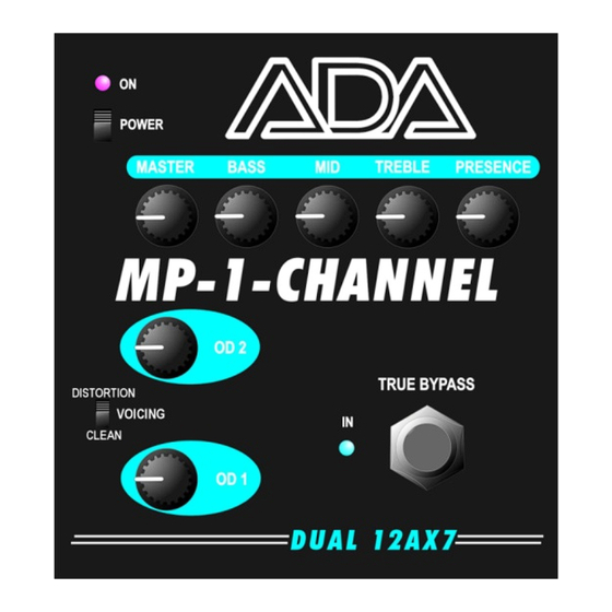
- Page 2 The ADA MP‐1‐CHANNEL is designed for the guitarist who wants the authentic tone of the renowned MP‐1 MIDI TUBE PREAMP in an effects pedal enclosure. The MP‐1‐CHANNEL uses the same vacuum tube design of the rack‐mounted MP‐1 PREAMP of the late 1980s to accomplish this goal. Two 12AX7 vacuum tubes create the tone – VOICED as CLEAN and DISTORTION for smooth warmth or sparkling definition to responsive overdrive and high‐gain distortion. The signal is then passed through the ADA tone stack for shaping and harmonic emphasis. The MP‐1‐CHANNEL pedal has a True Bypass foot switch and runs off a standard 12‐volt AC adapter. Inside the MP‐1‐CHANNEL the voltage is increased to 270 volts to obtain the best performance possible from the 12AX7s. Unlike the original MP‐1, the MP‐1‐CHANNEL is not MIDI programmable, not stereo and has no chorus effect. The MP‐1‐CHANNEL is a single channel, mono pedal. POWERING UP The best way to power up the MP‐1‐CHANNEL is to set the POWER switch off, plug in the AC adapter (ADA part number 240005) or pedal board power supply (12V at 800mA), and turn on the power supply, but not the MP‐1‐CHANNEL. Then set the MP‐1‐CHANNEL POWER switch on. The vacuum tubes require a lot of current to stay hot, and some power supplies cannot provide this. We recommend the ADA AC adapter because some generic AC adapters will “shut down” for protection and cause the MP‐1‐CHANNEL POWER LED to flash a few times before staying on. This does not cause any damage, but can be a bit annoying. After the tubes warm up, the guitar signal is passed to the OUTPUT jack. Page 2...
- Page 3 Note that the connector is a 2.1mm with the center pin negative, the most common configuration for effects pedals. There is no 9V battery in the MP‐1‐CHANNEL, and the MP‐1‐ CHANNEL will not work with a 9VDC power supply, nor will it work on a 12V power source with less than 800mA of current. APPLICATIONS The MP‐1‐CHANNEL was designed for pedal boards and direct recording. You can precede it with other pedals and effects or you can place them after the MP‐1‐CHANNEL. Most common effects after the MP‐1‐CHANNEL are delays, cabinet simulators, and reverb. Some guitarists will want the MP‐1‐CHANNEL to perform the function of a preamp, and will want its OUTPUT to connect to a combo amp’s power stage via a “direct insert” jack or the effects return loop jack. This avoids a preamp plugged into another preamp situation, which is, in most cases, undesirable. If your combo or head does not allow direct access to its power amp, you can plug into the combo or head’s input. When doing this, it is best to set the tone controls “flat” and “drive” turned down to keep the signal clean with the master volume up. This will allow the MP‐1‐CHANNEL to be the source of distortion, rather than sharing it with the combo or head preamp. For live performance, the MP‐1‐CHANNEL, along with a GCS Cabinet Simulator, can eliminate the need for a combo or head with a guitar speaker cabinet. You can get incredible tone through the house sound system (PA) and through full‐range stage monitors or ear monitors. For direct recording, we recommend a cabinet simulator like one of our GCS products. This will add the realism of a miked guitar speaker cabinet to the guitar tone coming from the MP‐1‐ CHANNEL, or your pedal board. Page 3...
- Page 4 CONTROLS Like the MP‐1, the MP‐1‐CHANNEL has two controls, OD1 and OD2, to set the drive level of the first two stages and the following stages 3 and 4. With this flexibility, the guitarist can not only set the amount of distortion, but control the level of even and odd harmonic distortion. Even harmonics are generated by clipping one side of the guitar signal instead of both the top and bottom sides of the signal for odd harmonic distortion. Even harmonics are smooth and hollow, while odd harmonics are crunchy, harsh and, with proper setting of the tone stack, “hairy.” Try some of the settings shown below to help get you familiar with how the controls work. There is one INPUT jack and one OUTPUT jack. Keep in mind that the MP‐1‐CHANNEL is a stomp box and runs at INSTRUMENT levels, not LINE levels. The VOICING switch sets the 12AX7 gain and drive equalization for CLEAN and DISTORTION biasing. The MASTER control sets the level of the signal coming from the four gain stages of the 12AX7s. (There are 2 stages per 12AX7 vacuum tube.) The tone stack (BASS, MID, TREBLE and PRESENCE) is an active filter which means it can cut AND boost the signal. When all the tone stack controls are set to 12:30 o’clock, the frequency response is “flat” – no boost or cut. There is a difference between the MID controls of the original MP‐1 and the MP‐1‐CHANNEL. ADA increased the range of the MID control in the MP‐ 1‐CHANNEL so modern guitar players can get a radical “scoop” of the mid frequencies. The amount of MID boost has also been increased so players can get a “low‐power combo with a 10‐inch speaker” sound for fuzzy comping and soloing. Page 4...
- Page 5 TUBES Preamp tubes last longer than power amp tubes and the need to change them occurs only after thousands of hours of playing. It is still best to turn the POWER switch off when not playing through the MP‐1‐CHANNEL. This will lengthen the life of the tubes. When replacing the 12AX7 vacuum tubes, always use high‐gain, low‐noise selected tubes for best performance and the lowest noise. At high gain settings the inherent mechanical (microphonic) noise can become an issue, so be careful not to tap, kick or bump the MP‐1‐CHANNEL while playing at high gains. The mechanical noise will show up in your sound. QUICK HOOK‐UP When using a combo amp or a head and guitar cabinet. Set the POWER switch on the MP‐1‐CHANNEL to its OFF position. Plug in the supplied AC adapter (12VDC at 800mA, 2.1mm plug, center negative) to the MP‐1‐CHANNEL. Turn on the source power to the AC adapter. Set all the controls to 12:30 o’clock except OD1, which is set at full counter clockwise. Set VOICING switch to CLEAN Set the TRUE BYPASS foot switch to bypass, LED off. Connect your guitar via a high quality cable to the INPUT of the MP‐1‐CHANNEL Page 5...
-
Page 6: Vacuum Tube Replacement
Connect the OUTPUT of the MP‐1‐CHANNEL to the power amp insert jack or effects return jack of your combo or head. Set the POWER switch on the MP‐1‐CHANNEL to ON. In about 20 seconds the vacuum tubes will warm up and signal will be available at the OUTPUT jack. 10. Turn on your combo or head. 11. Set your guitar volume knob to full and adjust the volume of the amplifier to a suitable level. 12. Set the TRUE BYPASS foot switch to on, blue LED is on. 13. Slowly turn up the OD1 control. You should hear the guitar in your speaker. 14. Adjust the OD1 and OD2 for the amount of overdrive you want. 15. Adjust the BASS, MID, TREBLE and PRESENCE controls for the tone you want. 16. Adjust the MASTER for the volume level you want. 17. Switch the VOICING to DISTORTION, and adjust your MASTER for the volume level, and make tonal changes using the BASS, MID, TREBLE and PRESENCE controls. VACUUM TUBE REPLACEMENT If you want to replace the 12AX7 vacuum tubes in the MP‐1‐CHANNEL, you must take the bottom panel off. WARNING there are high voltages inside the MP‐1‐CHANNEL, so we recommend a qualified service person for this task. Unplug the AC adapter from the MP‐1‐CHANNEL and let it sit for at least 1 hour. This will discharge the internal high voltage. Remove ONLY the six screws shown in the photographs below. Note that one screw at the lower center of the back panel has a lock washer. This washer and screw must be replaced when putting the bottom panel back. Do not remove the Page 6... - Page 7 other screw towards the center of the back panel. This screw also has a lock washer and serves as the ground connection for the enclosure. The bottom panel can be slid off. Note that the bottom panel has a cutout for the INPUT and OUTPUT jacks, and must be re‐installed the same way with this cutout around the jacks. The vacuum tubes can be pulled out of their sockets and, when replaced, be sure that each is fully seated in the socket and straight. Another way to discharge the high voltage is to place a metal‐tipped screw driver between the two points on the printed circuit board as shown in the picture below. Page 7...
-
Page 8: Troubleshooting And Technical Support
Note the tube nearest the edge of the front of the enclosure is the first stage of the MP‐1‐CHANNEL circuit and is the most critical tube for minimizing noise and microphonics. The first triode stage is pins 7, 8, 9 of the 12AX7. When reassembling the enclosure, do not over tighten the screws. If there is hum in the audio signal, check the rear panel screw with the lock washer for proper tightness so the lock washer makes electrical contact with the enclosure. Use only high quality, low‐noise 12AX7s. TROUBLE‐SHOOTING & TECHNICAL SUPPORT What are some quick tests to troubleshoot my unit? Sometimes a few quick tests at home can be the difference between thinking your unit is broken and getting it working properly. Here is a list of quick trouble‐shooting steps to test your gear and unit. As basic as these sound please run all the tests. Check simple signal chain: Plug your cable from your guitar into your amp. If you have a direct connect tone go to step 2. If not you have a bad cable, guitar or amp. Check 2nd cable: Take your #2 cable and switch it with the first cable. If you have sound, we now know both cables, your guitar and amp, work. Check power: Plug your amp into the same outlet that you’re using to power your ADA product. If the amp turns on, then the outlet works. If not try another outlet to power your unit. Check native ADA Signal Chain: Plug the #1 cable from your guitar into your ADA product (input). Plug the #2 cable between your ADA product (output) and into your amp. Make sure the ADA is plugged into a working power source. DO NOT insert it in a pedal chain, i.e., do not introduce any other pedals into the signal Page 8... - Page 9 What do I do if my product is not working? If your product is not working we STRONGLY suggest that you run a series of quick tests to troubleshoot the unit (see above). They may sound very basic, but it can save you time in getting your unit working and you back to playing. If you are an international (non‐USA) customer, you must contact your local dealer and/or your national distributor for repair. If you are in the USA and the unit truly does not work, email support@adaamps.com to get a Return Authorization (RA) number from us. What do I do after receiving my RA number? You will need to box your unit, write your Return Authorization (RA) number on the outside of the shipping box in a large bold lettering, and send it to the address supplied with the RA you received from us. You are responsible for shipping to and from ADA, so please track and insure your parcels. ADA cannot be held responsible for parcels that are lost or damaged in the shipping process. ADA cannot accept your shipment if there is no RA number written on the outside of the box. Page 9...
-
Page 10: Returning Units For Service
SERVICE If your unit requires service, please go to our website’s SERVICE page for information to help you find a solution to the problem you are having with your MP‐1‐CHANNEL. We have provided you with a step‐by‐step troubleshooting procedure to get you back up and running if you are experiencing a simple problem. RETURNING UNITS FOR SERVICE If you still need to send in your ADA product for service, YOU MUST FIRST GET A RETURN AUTHORIZATION NUMBER (RA) BEFORE YOU SHIP TO OUR SERVICE CENTER. Items shipped to us without an RA, will not be accepted by our Service Center and will be returned to you by the shipper. You can get an RA number by first contacting us online at: www.adaamps.com/service. You will need to have your serial number, approximate date of purchase and the name of the place that you purchased your MP‐1‐CHANNEL. DO NOT SHIP YOUR MP‐1‐CHANNEL TO OUR SERVICE CENTER BEFORE GETTING AN RA (Return Authorization Number) FROM US. Ship to: ADA Amplification 1170 Burnett Avenue Suite N Concord, California 94520 United States Page 10... -
Page 11: Specifications
SPECIFICATIONS INPUT IMPEDANCE: 500K ohms OUTPUT IMPEDANCE: 470 ohms SIGNAL LEVELS: Instrument to Line, ‐20dBu to 0 dBu, nominally unity gain POWER SUPPLY External Power Supply Requirement: 12VDC at 800 mA 2.1mm x 5.5mm x 10mm DC Power Plug, center pin negative. DIMENSIONS 5 x 5.4 x 2.3 inches (width x length x height) 12.7 x 13.7 x 5.84 cm (width x length x height) WEIGHT MP‐1‐CHANNEL weight: 1.75 lbs. Shipping weight: 2.35 lbs. with AC Adapter ONLINE www.adaamps.com Facebook: facebook.com/ADARocks ADA online store for accessories: http://adaamps.com/store/ Page 11... - Page 12 WARRANTY Your ADA MP‐1‐CHANNEL is warranted against defects in material and workmanship for a period of three‐hundred and sixty five (365) days from date of purchase. This warranty is to the original owner and is non‐transferable. During the warranty period, ADA or its agent will, at its sole option, repair or replace defective parts and make necessary repairs to the product which is defective at no charge. If the failure is the result of misuse, abuse, accident or misapplication, ADA has no obligation to repair or replace the failed product. ADA retains the right to make such determination on the basis of factory inspection. ADA will not be responsible for any speaker or device damaged by the MP‐1‐CHANNEL. This warranty remains valid only if repairs are performed by ADA or its agent and provided that the serial number on the unit has not been defaced or removed. This warranty is expressly in lieu of all other warranties either expressed or implied. This warranty gives you specific rights. You may have other rights that vary from state to state in the U.S. PART NUMBER: 701420 rev. 0.1 Page 12...
- Page 13 SOME BASIC MP‐1‐CHANNEL SETTINGS At the end of this User Manual are some of our favorite settings for various styles of playing. They serve as a good starting point in creating your own tone. The settings were made using a single coil pickup with the tone and volume knobs on the guitar set to maximum. Page 13...
- Page 14 DISTORTION VOICINGS 1 – 7 1. 80s OVERDRIVE 2. 70s ROCK Page 14...
- Page 15 3. MODERN SCOOP 4. MODERN MID BOOST Page 15...
- Page 16 5. SMOOTH LEAD 6. NU METAL Page 16...
- Page 17 7. THRASH Page 17...
- Page 18 CLEAN VOICINGS 8 – 11 8. SINGLE COIL CLEAN 9. CRUSTY/ TWANG Page 18...
- Page 19 10. FUNK 11. JAZZ Page 19...
Need help?
Do you have a question about the MP-1-CHANNEL and is the answer not in the manual?
Questions and answers