Table of Contents
Advertisement
Quick Links
PCE Americas Inc.
PCE Instruments UK Ltd.
711 Commerce Way
Units 12/13
Suite 8
Southpoint Business Park
Jupiter
Ensign way
FL-33458
Hampshire / Southampton
USA
United Kingdom, SO31 4RF
From outside US: +1
From outside UK: +44
Tel: (561) 320-9162
Tel: (0) 2380 98703 0
Fax: (561) 320-9176
Fax: (0) 2380 98703 9
info@pce-americas.com
info@industrial-needs.com
www.pce-instruments.com/english
www.pce-instruments.com
Manual
CO2 Analyser PCE-WMM 50
Version 1.0
Date of creation: 31.05.2016
Date of last change: 28.11.2017
Advertisement
Table of Contents

Related Manuals for PCE Instruments PCE-WMM 50


Summary of Contents for PCE Instruments PCE-WMM 50
- Page 1 From outside UK: +44 Tel: (561) 320-9162 Tel: (0) 2380 98703 0 Fax: (561) 320-9176 Fax: (0) 2380 98703 9 info@pce-americas.com info@industrial-needs.com www.pce-instruments.com/english www.pce-instruments.com Manual CO2 Analyser PCE-WMM 50 Version 1.0 Date of creation: 31.05.2016 Date of last change: 28.11.2017...
-
Page 2: Table Of Contents
Operation ....................... 12 Further measuring functions ..................... 12 Settings ............................. 13 Maintenance ......................14 Repair, cleaning and maintenance ................... 14 Troubleshooting ........................16 Warranty ......................... 16 Disposal ......................... 17 Contact ........................17 PCE Instruments UK ........................ 17 PCE Americas .......................... 17... -
Page 3: Safety Notes
Please read this manual carefully and completely before you use the device for the first time. The device may only be used by qualified personnel and repaired by PCE Instruments personnel. PCE Instruments cannot be held liable for any damage or injuries caused by non-observance of the manual. -
Page 4: Specifications
Manual Safety symbols Safety-related instructions the non-observance of which can cause damage to the device or personal injury carry a safety symbol. Symbol Designation / description General safety symbol Non-observance can cause personal injury and/or damage to the device. Warning of electric voltage Non-observance can cause electric shocks. -
Page 5: Delivery Content
Function test, Reset, menu selection, Enter, shifting between °C and °F Enclosure aluminium, IP 54, splash-water proof Voltage supply via data cable to gas detector Dimensions 118 x 85 x 34 mm (without connections) Delivery content 1 x gas detector PCE-WMM 50 1 x instruction manual... -
Page 6: System Description
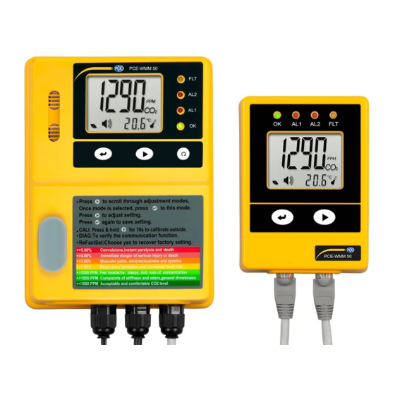
Manual System description Device The gas detector PCE-WMM 50 is equipped with a buzzer as well as a visual indication. These are activated when the CO concentration reaches or exceeds a threshold previously set. Also, high CO concentrations activate a potential-free contact which can, for instance, activate a fan which reduces the increased CO concentration in the room concerned. - Page 7 Manual The sensor unit must be installed in the room to be inspected, such as a room where CO gas bottles are stored. The LC display shows the CO concentration in the ambient air as well as the temperature. When the green LED glows constantly, the power supply of the device is granted.
- Page 8 Manual Remote display unit Green LED (power supply) Red LED 1 (AL1 ) Red LED 2 ( AL2) Yellow LED (error indication) LC display Enter key Mode key RJ45 connection (Output) RJ45 connection for sensor unit (Input) Buzzer...
-
Page 9: Display
Manual Display Symbol Meaning Description concentration in ppm concentration in the monitored room Temperature (degrees Centigrade) Temperature in the monitored room in degrees Centigrade Temperature (degrees Fahrenheit) Temperature in the monitored room in degrees Fahrenheit Alarm Alarm icon Diagnosis Test of communication between the sensor unit and the remote display unit First alarm threshold... -
Page 10: Getting Started
The connection between both devices can be checked by using the “DIAG” function which is described in the further course of this manual. To reset the PCE-WMM 50, the “Reset” key on the sensor unit is used. Getting started... -
Page 11: Power Connection
Manual Connect the sensor unit to the remote display unit by using the communication cable which is wired to the sensor unit. Make sure the cable is run properly and attach it to the wall by using cable clips. Once it is plugged in the remote display unit, the devices can communicate with each other. -
Page 12: Operation
When you take the PCE-WMM 50 out of its box, remove the protective rubber cap from the gas input (M) and put it in position L. During operation, you should make sure that the gas input (M) is not blocked. -
Page 13: Settings
Manual Restore factory settings Using this function deletes all stored settings and sets the device back to factory default settings. This might be reasonable if the calibration has not been done properly, for example. To reset the gas detector, press the “Mode” key until “ReFactSet” appears on the display. Now press the “Enter”... -
Page 14: Maintenance
Do not try to repair the gas detector on your own and do not manipulate the circuits. If the device is broken, please send it back to PCE Instruments. Our trained personnel will repair the device, if possible, and send it back to you. - Page 15 Manual Cleaning Before cleaning the gas detector, unplug the mains adaptor. Then clean the device with a damp cloth. Use only pH neutral cleaner, no abrasives or solvents. Liquid cleaning agents might damage the device. Before cleaning the room where the sensor unit is located, put the protective rubber cap on the gas input (M) to prevent water from getting into the device.
-
Page 16: Troubleshooting
Manual Troubleshooting Indication Error code Possible cause Sensor unit Remote display Possible solution unit - “Er3” flashing - “Er3” flashing Ambient temperature Indications - LED “FLT” - LED “FLT” exceeds measuring range disappear once (0 … +50 °C // 32 … 122 flashing flashing the ambient... -
Page 17: Disposal
In order to comply with the EU directive 2012/19/EU we take our devices back. We either re-use them or give them to a recycling company which disposes of the devices in line with law. If you have any questions, please contact PCE Instruments. Contact If you have any questions about our range of products or measuring instruments please contact PCE Instruments.
Need help?
Do you have a question about the PCE-WMM 50 and is the answer not in the manual?
Questions and answers