Table of Contents
Advertisement
Advertisement
Table of Contents

Related Manuals for Ultraflex Power A Mark II


Summary of Contents for Ultraflex Power A Mark II
- Page 1 Owner's manual ELECTRONIC CONTROL SYSTEM PARTNER (Dr. No. 28394/a 16/02/2015)
- Page 2 Products for pleasure boats are constantly tested to check their conformity with the 2013/53/EU. "ULTRAFLEX has over 80 years of experience in the marine industry and is a world leader in the production of mechanical, hydraulic and electronic steering systems, control boxes and steering wheels for any kind of pleasure, fishing or commercial boats.
-
Page 3: Table Of Contents
ULTRAFLEX Owner's manual TABLE OF CONTENTS DOCUMENT REVISIONS........................4 MANUAL SYMBOLS USED..................5 INFORMATIVE LETTER..........................6 WARRANTY..........................6 SECTION 1 - PRODUCT DESCRIPTION PRODUCT DESCRIPTION ........................... 7 SECTION 2 - USE CONTROL DESCRIPTION.......................9 OPERATION OF THE CONTROL STATION LEVERS............10 SYSTEM START ..............................11 2.3.1 SYSTEM POWER SUPPLY......................11... -
Page 4: Document Revisions
ULTRAFLEX Owner's manual DOCUMENT REVISIONS Rev. Date Revision description 02/09/2011 First edition page 4 of 36- POWER A MK2... -
Page 5: Manual Use And Symbols Used
ULTRAFLEX Owner's manual MANUAL USE AND SYMBOLS USED THE INSTALLATION AND MAINTENANCE MANUAL is the document accompanying the product from sale to replacement and discharge. The manual is an important part of the product itself. It is necessary to read carefully the manual, before ANY ACTIVITY involving the product, handling and unloading included. -
Page 6: Informative Letter
ULTRAFLEX declines all responsibility for possible mistakes in this manual due to printing errors. Although the main features of the type of product described are not subject to change, ULTRAFLEX Company reserves the right to modify any parts, details and accessories it deems necessary to improve the product or for manufacturing or commercial requirements, at any time and without being obliged to update this manual immediately. -
Page 7: Product Description
ULTRAFLEX Owner's manual 1 PRODUCT DESCRIPTION system is made up of a series of intelligent modules which communicate via a proprietary CAN bus. They altogether control the boat propulsion engines, and at the same time allow the adjustment of the boat attitude stabilizers. - Page 8 ULTRAFLEX Owner's manual If the throttle is electronic, there will be an analogue or digital dedicated interface. Throttles with under-voltage analogue interface or PWM are provided with the V-throttle unit. Similarly, throttles with under-current analogue interface are provided with the I-throttle unit, which is externally identical to the V-throttle unit.
-
Page 9: Section 2 - Use
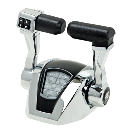
ULTRAFLEX Owner's manual 2 USE 2.1 Control description The picture below shows an enlargement of the user interface located on the control stations. The interface is the same for twin-engine stations with or without trim switches. 4 keys and 8 LED indicators are located on the user interface. -
Page 10: Operation Of The Control Station Levers
ULTRAFLEX Owner's manual 2.2 Operation of the control station levers In case of single-engine boats, the control stations are provided with a lever (the port lever); in case of twin- engine boats, the control stations are provided with two levers: the port lever controls the port engine and the starboard lever controls the starboard engine. -
Page 11: System Start
ULTRAFLEX Owner's manual 2.3 System start To correctly start the system, follow the steps below: 2.3.1 System power supply First of all supply the system with power by means of the thermal switch located on the power cord. The switch must be set to the ON position (switch closed). If there are two power cords and, therefore, two thermal switches, make sure that both of them are set to the ON position. -
Page 12: Engine Switching On
ULTRAFLEX Owner's manual 2.3.3 Engine switching on It is possible to switch on the engines if the following conditions are met: 1) The lever must be set to the neutral position; a click is heard when placing the lever vertically in order to reach such a position. -
Page 13: Multiple Control Stations
ULTRAFLEX Owner's manual To control the other side too, check the points described above then press key CTRL. If the engine key is disabled while the station is enabled, the relevant LED will switch off indicating that that side is disabled. -
Page 14: Use Modes
ULTRAFLEX Owner's manual 2.4 Use modes After enabling the desired station, it is possible to put into reverse or forward gear and adjust the engine speed by moving the levers. Similarly, if this function has been set up, the trim attitude can be modified by means of the two trim switches on the port lever. -
Page 15: Autosync Mode
ULTRAFLEX Owner's manual WARNING In twin-engine systems the WARM-UP mode can be disabled only on one engine: the proper LED will indicate the engine on which this mode is enabled. It is possible that the WARM-UP mode is enabled only on one engine and the control station meets the conditions listed previously (levers in neutral positions, no failure): in this case, when pressing key WARM again, this mode will be disabled on the engine on which it was enabled and viceversa. -
Page 16: High-Idle Mode
ULTRAFLEX Owner's manual 2.4.3 HIGH-IDLE mode The HIGH-IDLE mode allows the user to increase the engine idle speed. To enable this mode the following conditions must be met: - The station must be enabled. - The DOCKING mode must not be enabled. -
Page 17: Troll Mode
ULTRAFLEX Owner's manual 2.4.4 Troll mode The TROLL mode allows the user to control the trolling-valve of each engine. To enable this mode the following conditions must be met: - The station must be enabled. - All the other fucntions must be disabled. -
Page 18: Docking Mode
ULTRAFLEX Owner's manual 2.4.5 Docking mode The DOCKING mode allows the user to reduce the maximum engine speed without reducing the lever angular travel. The DOCKING mode allows a higher sensitivity on throttle, therefore it is suitable for docking. To enable this mode the following conditions must be met: - The station must be enabled. -
Page 19: Panel Brightness Adjustment
ULTRAFLEX Owner's manual 2.4.6 Panel brightness adjustment It is possible to increase or reduce the LED brightness on the user interface by keeping key WARM pressed for a few seconds. Each second the key is kept pressed, the LED brightness will increase up to the maximum value. -
Page 20: Section 3 - Warnings And Alarms
ULTRAFLEX Owner's manual 3 WARNINGS AND ALARMS The system warns the operator about failures by means of the control station (visual and acoustic signals) and the control unit display. The central red LEDs on the user interface show failures. A buzzer inside the lever produces a sound that can be stopped by keeping key HIGH IDLE pressed for a few seconds. -
Page 21: Control Station
ULTRAFLEX Owner's manual 3.1 Control station Alarm code Meaning Solution Check the CAN bus connection or Miss shift msg The system has detected the lack of the power cord of the unit port CAN message of the port shift. controlling the shift. - Page 22 ULTRAFLEX Owner's manual Contact the technical assistance Problem in the control station Pll fault service to replace the control processor. station Contact the technical assistance Problem in the control station Miss parameters service to replace the control processor. station. page 22...
-
Page 23: V-Throttle, I-Throttle, Pwm-Throttle, Saej-Throttle
ULTRAFLEX Owner's manual 3.2 V-throttle, I-throttle, PWM throttle, SAEJ-throttle Alarm code Meaning Solution Check the CAN bus connection or Miss shift msg The system has detected the lack of the power cord of the unit port CAN message of the port shift. -
Page 24: Shift Unit
ULTRAFLEX Owner's manual 3.3 Shift unit Alarm code Meaning Solution Check the CAN bus connection or Miss acc msg The system has detected the lack of the power cord of the unit port CAN message of the port throttle controlling the throttle. - Page 25 ULTRAFLEX Owner's manual The system has detected a problem Check the connection reliability and Nt fbk fault stbd on the neutral solenoid valve, if it is the suitability of the solenoid valve. used (starboard) The system has detected a heavy...
-
Page 26: Mechanical Actuator Used As Throttle
ULTRAFLEX Owner's manual 3.4 Mechanical actuator used as throttle Alarm code Meaning Solution Check the CAN bus connection or The system has detected the lack of Miss shift msg the power cord of the unit CAN message of the shift. - Page 27 ULTRAFLEX Owner's manual Check the electrical connections that feed the system, check the The system has turned off the actuator as PWM off battery charge. Then turn off and on a precaution after a heavy brownout. the system by means of the...
-
Page 28: Mechanical Actuator Used As Shift
ULTRAFLEX Owner's manual 3.5 Mechanical actuator used as shift Alarm code Meaning Solution Check the CAN bus connection or The system has detected the lack of Miss acc msg the power cord of the unit CAN message of the throttle. - Page 29 ULTRAFLEX Owner's manual Check the electrical connections The system has turned off the that feed the system, check the PWM off actuator for precaution after a heavy battery charge. Then turn off and on brownout. the system by means of the...
-
Page 30: Control Unit
ULTRAFLEX Owner's manual 3.6 Control unit Alarm code Meaning Solution Check the CAN bus connection or Miss shift msg The system has detected the lack of the power cord of the unit port CAN message of the port shift. controlling the shift. - Page 31 ULTRAFLEX Owner's manual The system has detected a problem Contact the technical assistance Wrong software of incompatibility among the different service to replace the unsuitable software versions of the components. components. Problem on the control unit Contact the technical assistance Miss parameters processor.
-
Page 32: Section 4 - Safety Warnings
4.1 Safety standards during installation and use RESPECT STRICTLY the following safety rules: ULTRAFLEX declines all responsibility in case the user does not follow these rules and it is not responsible for negligence during the use of the system. DANGER - DO NOT PUT HANDS BETWEEN THE MOVING PARTS. -
Page 33: Section 5 - Maintenance
ULTRAFLEX Owner's manual 5 MAINTENANCE 5.1 Routine maintenance The routine maintenance consists in a series of periodical checks and actions to keep the product in optimum operating condition thus avoiding that the external environment may jeopardize its operation and safety. -
Page 34: Section 6 - Dismantling
ULTRAFLEX Owner's manual 6 DISMANTLING 6.1 Dismantling When for any reason, the system is put out of service, it is necessary to follow some rules in order to respect the environment. Sheaths, pipelines, plastic or non-metallic components must be disassembled and disposed of separately. -
Page 35: Enclosures
ULTRAFLEX Owner's manual ENCLOSURES page 35 of 36 POWER A MK2... - Page 36 ULTRAFLEX Owner's manual Cable compatibility: Mercruiser stern drive cable: use the 2 bushes provided to adapt it to the locking system. C2, C7, C8 and MACHZero cables, use the adaptors included in each actuator. Mounting of adapters on cables: Mercruiser stern drive cable: insert the two pressure bushes on the cable cylinder, mount the cable on the locking system according to the procedure described in paragraph 6.4 of the Installation manual.
Need help?
Do you have a question about the Power A Mark II and is the answer not in the manual?
Questions and answers