Table of Contents
Advertisement
Installation & Operating Manual
Installation and Appliance Setup - Care and Operation
INSTALLER: Leave this manual with party responsible for use and operation.
OWNER: Retain this manual for future reference.
Call your dealer for questions on Installation, Operation, or Service.
NOTICE: SAVE THESE INSTRUCTIONS
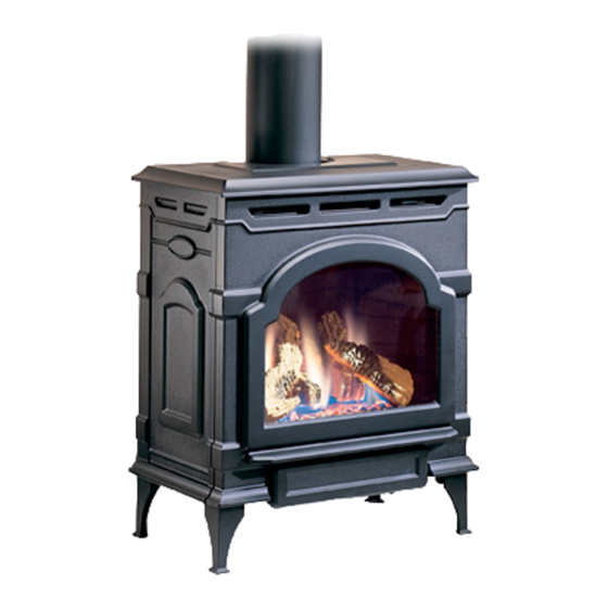
Oxford Direct Vent Gas Stove
Models:
OXDV30SP, OXDV30-IPI
CERTIFIED
S
B
AFETY
ARRIER
5123
Oxford cover
Installation and service of this appliance should be performed by
qualified personnel. Hearth & Home Technologies recommends
HHT Factory Trained or NFI certified professionals.
11
Hearth and Home Technolgies • Oxford Direct/Natural Vent Installation Manual_R3 • 02/19
!
FIRE OR EXPLOSION HAZARD
Failure to follow safety warnings exactly could result
in serious injury, death or property damage.
•
Do not store or use gasoline or other flammable
vapors and liquids in the vicinity of this or any
other appliance.
•
WHAT TO DO IF YOU SMELL GAS
– Do not try to light any appliance.
– Do not touch any electrical switch; do not use
any phone in your building.
– Leave the building immediately.
– Immediately call your gas supplier from a
neighbor's phone. Follow the gas supplier's
instructions.
– If you cannot reach your gas supplier, call the
fire department.
•
Installation and service must be performed
by a qualified installer, service agency or the
gas supplier.
DANGER
A barrier designed to reduce the risk of burns from
the hot viewing glass is provided with this
appliance and shall be installed.
DANGER
WARNING
HOT GLASS WILL
CAUSE BURNS.
DO NOT TOUCH GLASS
UNTIL COOLED.
NEVER ALLOW CHILDREN
TO TOUCH GLASS.
Un panneau vitré chaud peut
causer des brûlures.
Laissez refroidir le panneau
3-90-30007480
vitré avant d'y toucher.
Ne laisser jamais les enfants
Advertisement
Table of Contents

Related Manuals for Hearth & Home OXDV30SP


Summary of Contents for Hearth & Home OXDV30SP
- Page 1 Models: • WHAT TO DO IF YOU SMELL GAS OXDV30SP, OXDV30-IPI – Do not try to light any appliance. – Do not touch any electrical switch; do not use any phone in your building. – Leave the building immediately.
-
Page 2: Table Of Contents
PLEASE READ THE INSTALLATION & OPERATING INSTRUCTIONS BEFORE USING APPLIANCE. Thank you and congratulations on your purchase of a Hearth and Home Technologies stove. IMPORTANT: Read all instruc- tions and warnings carefully before starting installation. Failure to follow these instructions may result in a possible fire hazard and will void the warranty. -
Page 3: Important Safety Information
Important Safety Information The Oxford Direct Vent Room Heater, Model No. OXDV30SP, The Oxford Direct Vent Room Heater, when installed, must be OXDV30IPI, is a vented gas appliance listed to the ANSI Standard electrically grounded in accordance with local codes or, in the Z21.88-2017 and CSA 2.33-2017 for Vented Room Heaters, and... -
Page 4: Massachusetts Safety Information
A. Massachusetts Safety Information Exemptions The following equipment is exempt from 248 CMR 5.08(2) Requirements for the Commonwealth of Massachusetts (a)1 through 4: All gas fitting and installation of this heater shall only be done • The equipment listed in Chapter 10 entitled “Equipment by a licensed gas fitter or licensed plumber. -
Page 5: Framing And Clearances
Framing and Clearances A. Appliance Dimension Diagram Stove Dimensions 6-3/4" (172mm) Valve Inlet 24-1/2" (622mm) 28-3/8" (721mm) C L Valve 4-3/8" Inlet (111mm) 12-1/2" 23" (318mm) (584mm) 17" (419mm) 5123 Weight: Fully assembled; 202 lbs. Oxford dims Figure 2.1 - Oxford dimensions. Attention The Oxford stove is shipped from the factory as a Direct Vent Gas Heater. This heater may be converted into a Natural Vent unit in the field. If a Natural Vent heater is desired, the FSDHAGSLP Draft Hood must be directly... -
Page 6: Installation Requirements
B. Installation Requirements Direct Vent System Only The installation must conform with local codes or, in the absence of local codes, with the National Fuel Gas Code, ANSI Z223.1/NFPA 54 - latest edition. (EXCEPTION: Do not derate this appliance for altitude. Maintain the manifold pressure at 3.5"... -
Page 7: Hearth Requirements
D. Hearth Requirements Wall Centerline from Floor The Oxford Heater must be installed on rigid flooring. When the heater is installed directly on any combustible surface other than wood flooring, a metal or wood panel extending the full width and depth of the unit must be used as the hearth. -
Page 8: Gas Specifications
BTU/h BTU/h may extend up to 20’ (6m) and include a vertical rise of up to Natural Millivolt OXDV30SP 28,000 20,000 40’ (12 m). (Figure 7) Horizontal termination must also meet Manual the criteria shown in Figures 2.11 and 2.12. - Page 9 Vertical Termination Restrictor Plate Adjustment for Extended Pipe Runs A vertical vent system must terminate no less than 8’ (2.44 m) The Oxford stove is shipped with a restrictor plate in the Parts and no more than 40’ (12 m) above the appliance flue collar. Bag.
- Page 10 Vent Termination Clearances Your stove is approved to be vented either through the side When planning the installation, consider the location of the wall, or vertical through the roof. vent terminal and clearances. Some of the most common • HHT does not require any opening for inspection of vent clearances to keep in mind are shown in Figure 2.11.
-
Page 11: Chimney Diagram
H. Chimney Diagram INSIDE CORNER DETAIL Fixed Closed Fixed Operable Closed CFM145a AREA WHERE TERMINAL IS NOT PERMITTED VENT TERMINATION AIR SUPPLY INLET CANADIAN INSTALLATIONS US INSTALLATIONS CFM145a DV Termin Location A = Clearance above grade, veranda, porch, deck 12" (30cm) 12"... - Page 12 Termination Clearances Termination clearances for buildings with combustible and noncombustible exteriors. Inside Corner Alcove Applications* Outside Corner Combustible 6" (152 mm) Combustible 6" (152 mm) Noncombustible 2" (51 mm) Noncombustible 2" (51 mm) Balcony - Balcony - with no side wall with perpendicular side wall = Min.
-
Page 13: Assembly And Installation
Assembly and Installation A. Venting Requirements & Options DuraVent Components Approved Vent System Components Starter Pipe Assembly (incl. inner & outer 46DVA-ADP The Oxford Heater must be vented to the outdoors through sections) an adjacent exterior wall or through the roof. The venting 90°... -
Page 14: Assembling The Stove
B. Assembling the Stove: WARNING Tools Required • Phillips screwdriver (stub) Always maintain minimum clearances around vent • Utility knife systems. Rear/Top Vent Vertical Side wall: Horizontal • Metal drill bit: size 28 (.140"/3.5mm) sections of this vent system require a minimum of 3” (76 •... - Page 15 • These models are approved to use HHT direct vent WARNING pipe components, HHT termination kits and DuraVent components. No other venting system components may Any horizontal run must have a 1/4” rise for every one (1) be used. foot of run towards the vent termination. Never allow the •...
- Page 16 CCSLP Starter Figure 3.4 - Slip Section Pilot Holes Pipe Figure 3.2 - Attach inner assembly to flue collar. Assemble Slip Sections The outer flue of the slip section should slide over the outer flue of the pipe section and into (inner flue) the last pipe section, Figure 3.4.
- Page 17 WARNING Risk of Fire/Explosion/Asphyxiation! Improper support may allow vent to sag and separate. Use vent run supports and connect vent sections per installation instructions. DO NOT allow vent to sag below connection point to appliance. Figure 3.9 - Align and Disassemble Vent Sections Horizontal Termination Cap: WARNING Risk of Fire! The telescoping flue section of the...
- Page 18 Divert Roof Run-off Vent Opening for Combustible Walls HHT recommends, where excessive water run-off is possible, 9" use of one of the two options shown in Figure 3.10 to prevent (244 mm) water running off the roof and onto/into the horizontal termination cap. 9" (244 mm) Stove Hearth Framing Detail...
- Page 19 6. Use appropriate length of pipe sections – telescopic or Vent Termination Below Grade: fixed – and install. The sections which go through the Install Snorkel Kit #SLP-SNORK when it is not possible to wall are packaged with the starter kit, and can be cut to meet the required vent termination clearances of 12"...
- Page 20 Vertical Termination Wall Screws Waterproof Seal and Anchors Around Pipe Firestop Snorkel Termination Cap Storm Collar 4" Clearance Gravel Flashing Drain Window Well Offset RADIANCE Support Collar Firestop Spacer Figure 3.16 - Snorkel kit installation. Vertical Through-The-Roof Application/Installation: ST653 Note: Refer to Figures 2.8 thru 2.10 for restrictor plate install snorkel adjustments for vertical vent runs.
- Page 21 Decorative Horizontal overhang 7” Pipe HHT Direct Vent 20 in. System may be used 24 in. min. from Draft Hood up (508 mm) Vertical 4” B-vent (610 mm) to the ceiling wall Pipe Lowest Discharge Draft Hood Opening Adapter Termination Storm Collar Roof Roof Pitch...
- Page 22 Figure 3.20 - Install draft hood adapter. Install the Log Set 1. Remove the logs from their packaging, and inspect each piece for damage. DO NOT INSTALL DAMAGED ST767 LOGS. 2. Install the rear log by centering it to the rear of the firebox attach draft hood on the sheet metal shelf, Figure 3.21.
-
Page 23: Gas Information
Gas Information A. Fuel Conversion C. Gas Connection • Make sure the appliance is compatible with available gas • Pipe incoming gas line into valve compartment. types. • Connect incoming gas line to the 1/2 in. (13 mm) • Conversions must be made by a qualified technician connection on manual shutoff valve. -
Page 24: Gas Supply Line Connection
E. Gas Supply Line Connection Air Shutter Adjustment The Oxford is shipped from the factory with the air shutter Check the Rating Plate attached by a steel cable to the adjusted to the minimum allowed opening. Refer to Table 1. firebox, to confirm that you have the appropriate firebox for Based on the altitude where the stove is located, a shutter the type of fuel to be used. - Page 25 3. Pull the top edge of the glass and frame assembly away Front Injector Air Shutter from the firebox, and lift it off its supports on the bottom Air Inlet (May be adjusted up to fully open) of the firebox face. Place the assembly out of the way on Burner a flat, padded surface such as a counter protected by a towel.
-
Page 26: Thermostat Connection (Optional) Millivolt
Complete the Assembly • Open the swiveling latches (cams) on the top left and right corners of the glass frame. • Position the glass and frame against the firebox by placing the bottom edge on the brackets on the bottom face of the firebox. 3/8”... -
Page 27: After Appliance Is Lit
H. After Appliance is Lit I. Flame Adjustment Control Initial Break-in Procedure Some appliances come equipped with a high/low flame adjustment control. • The appliance should be run three to four hours continuously on high. • Open control access panel. •... -
Page 28: Electrical Information
Electrical Information A. Wiring Requirements D. Electrical Service and Repair NOTICE: This appliance must be electrically wired and WARNING! Risk of Shock! Label all wires prior to grounded in accordance with local codes or, in the absence disconnection when servicing controls. Wiring errors can of local codes, with National Electric Code ANSI/NFPA cause improper and dangerous operation. -
Page 29: Ipi Wiring Requirements
E. IPI Wiring Requirements NOTICE: Batteries should only be used as a power source in the event of an emergency power outage. Batteries should Intellifire™ Pilot Ignition System Wiring not be used as a primary long-term power source. Battery • Wire the appliance junction box to 110-120 VAC for polarity must be correct when installing batteries. -
Page 30: Fuel Conversion
F. Fuel Conversion • This appliance ships with a Natural Gas to Propane Conversions Kit with installation instructions included. • Make sure the appliance is compatible with available gas types. Spring fingers • Conversions must be made by a qualified service technician using Hearth &... -
Page 31: Operating Instructions
Operating Instructions A. Operation The Oxford is to be operated with the front glass in place. Ensure the safety barrier screen is in place during operation. B. Lighting Instructions Read these instructions carefully and familiarize yourself with the lighting instructions. Section F, “Lighting and Operating Instructions”. -
Page 32: Read Before Lighting
F. Read Before Lighting FOR YOUR SAFETY READ BEFORE LIGHTING WARNING If you do not follow these instruction exactly, a fire or explosion may result causing property damage, personal injury or loss of life. A. This appliance is equipped with an ignition device which automatically lights the pilot. Refer to the instructions. B. -
Page 33: Lighting And Operating Instructions
G. Lighting and Operating Instructions LIGHTING AND OPERATING INSTRUCTIONS (MILLIVOLT ONLY) FOR YOUR SAFETY READ BEFORE LIGHTING WARNING: If you do not follow these instructions exactly, a fire or explosion may result causing property damage, personal injury or loss of life. A. This heater has a pilot which must be lit manually. When C. Use only your hand to push in or turn the gas control lighting the pilot follow these instructions exactly. -
Page 34: Lighting Instructions (Ipi)
H. Lighting Instructions (IPI) FOR YOUR SAFETY READ BEFORE LIGHTING WARNING: If you do not follow these instructions exactly, a fi re or explosion may result causing property damage, personal injury or loss of life. • Immediately call your gas supplier from a neighbor’s phone. Follow the gas sup- A. -
Page 35: Lighting Troubleshooting
I. Lighting Troubleshooting SIT NOVA 820 MILLIVOLT VALVE NOTE: Before trouble shooting the gas control system, be sure external gas shut off is in the “On” position. Symptom Possible Cause Corrective Action 1. Spark ignitor will not light A. Defective or misaligned electrode at Using a match, light pilot. - Page 36 I. Lighting Troubleshooting (Continued) IntellifireTM Ignition System Symptom Possible Cause Corrective Action Incorrect wiring. Verify “S” wire (white) for sensor and “I” wire (orange) for ignitor are connected to correct terminals on module and pilot assembly. Loose connections or electrical shorts in Verify no loose connections or electrical the wiring.
- Page 37 Intellifire Ignition System - (continued) Symptom Possible Cause Corrective Action Gas supply. Verify that incoming gas line ball valve is “open”. Verify that inlet pressure reading is within acceptable limits. Ignitor gap is incorrect. Verify gap of igniter to right side of pilot hood. The gap should be approximately Pilot sparks, but Pilot will not light.
-
Page 38: Burner, Pilot & Control Compartment
J. Burner, Pilot & Control Compartment WARNING Turn off gas before servicing stove. It is recommended that a qualified service technician perform these check-ups at the beginning of each heating season Keep the control compartment and burner areas clean by vacuuming or brushing at least twice a year. -
Page 39: Cleaning And Maintenance
Cleaning and Maintenance D. Cleaning the Glass Your Oxford Gas Heater will provide years of service with minimal upkeep. The following procedures will help ensure It will be necessary to clean the glass periodically. During that your stove continues to function properly. start-up, condensation, which is normal, forms on the inside of A. -
Page 40: Gasket Replacement
F. Gasket Replacement OXDV MODELS The heater uses a ‘tadpole’ type gasket to seal between the glass panel and the frame. In time, this gasket can become brittle and compressed and should be replaced. New gasket is available from your dealer. Shut off the gas supply and allow the stove to cool. -
Page 41: Maintenance Frequency
I. Maintenance Frequency Burner Ignition and Operation Frequency: Annually Venting By: Service Technician Frequency: Seasonally Tools needed: Protective gloves, vacuum cleaner, whisk By: Homeowner broom, flashlight, voltmeter, indexed drill bit set, and a Tools needed: Protective gloves and safety glasses. manometer. -
Page 42: Wiring Diagrams
Wiring Diagrams Millivolt Wiring Diagrams POWER On/Off Switch Wiring CORD Chassis TP/TH Ground Millivolt Gas Valve Black Optional Thermostat Wiring Thermostat Thermostat FAN JUNCTION BOX (Optional) (Optional) Strain Relief St124b TP/TH on/off/switch ON / OFF Rheostat Millivolt wiring Gas Valve 1/11/00 djt Black Snapstat Figure 8.1 - On/Off switch and optional thermostat circuit. -
Page 43: Service Parts List
Service Parts List OXDV30SP Service Parts Oxford Direct Vent Gas Stove Beginning Manufacturing Date:June 2017 With Screen Barrier Ending Manufacturing Date: Active 15 17 IMPORTANT: THIS IS DATED INFORMATION. Parts must be ordered from a dealer or distributor. Stocked Hearth and Home Technologies does not sell directly to consumers. Provide model number and serial number when requesting service parts from your dealer or distributor. - Page 44 OXDV30SP Service Parts Beginning Manufacturing Date:June 2017 Ending Manufacturing Date: Active IMPORTANT: THIS IS DATED INFORMATION. Parts must be ordered from a dealer or distributor. Stocked Hearth and Home Technologies does not sell directly to consumers. Provide model number and serial number when requesting service parts from your dealer or distributor.
- Page 45 OXDV30SP Service Parts Beginning Manufacturing Date:June 2017 Ending Manufacturing Date: Active IMPORTANT: THIS IS DATED INFORMATION. Parts must be ordered from a dealer or distributor. Stocked Hearth and Home Technologies does not sell directly to consumers. Provide model number and serial number when requesting service parts from your dealer or distributor.
- Page 46 OXDV30-IPI Service Parts Oxford Direct Vent Gas Stove Beginning Manufacturing Date:Feb 2019 With Screen Barrier and IPI Controls Ending Manufacturing Date: Active Part number list on following page. 02/19 4646 Hearth and Home Technolgies • Oxford Direct/Natural Vent Installation Manual_R3 • 02/19 3-90-30007480...
- Page 47 OXDV30-IPI Service Parts Beginning Manufacturing Date:Feb 2019 Ending Manufacturing Date: Active IMPORTANT: THIS IS DATED INFORMATION. Parts must be ordered from a dealer or distributor. Stocked Hearth and Home Technologies does not sell directly to consumers. Provide model number and serial number when requesting service parts from your dealer or distributor. at Depot ITEM DESCRIPTION...
- Page 48 OXDV30-IPI Service Parts Beginning Manufacturing Date:Feb 2019 Ending Manufacturing Date: Active IMPORTANT: THIS IS DATED INFORMATION. Parts must be ordered from a dealer or distributor. Stocked Hearth and Home Technologies does not sell directly to consumers. Provide model number and serial number when requesting service parts from your dealer or distributor. at Depot ITEM DESCRIPTION...
-
Page 49: Optional Accessories
Optional Accessories Fan Kits Remote Controls The remote control allows you to turn the heater on or off FK26 Fan from anywhere in the room. The FK26 fan helps distribute heated air from within the firebox out into the room. The fan is controlled by a snapstat Model Functions Controlled that turns power on and off as the firebox temperature rises... -
Page 50: Warranty Policy
Warranty Policy Hearth & Home Technologies LIMITED LIFETIME WARRANTY Hearth & Home Technologies, on behalf of its hearth brands (“HHT”), extends the following warranty for HHT gas, wood, pellet and electric hearth appliances that are purchased from an HHT authorized dealer. WARRANTY COVERAGE: HHT warrants to the original owner of the HHT appliance at the site of installation, and to any transferee taking ownership of the appliance at the site of installation within two years following the date of original purchase, that the HHT appliance will be free from... - Page 51 WARRANTY CONDITIONS: • This warranty only covers HHT appliances that are purchased through an HHT authorized dealer or distributor. A list of HHT authorized dealers is available on the HHT branded websites. • This warranty is only valid while the HHT appliance remains at the site of original installation. •...
- Page 52 This warranty is void if: • The appliance has been over-fired, operated in atmospheres contaminated by chlorine, fluorine, or other damaging chemicals. Over-firing can be identified by, but not limited to, warped plates or tubes, deformation/warping of interior cast iron structure or components, rust colored cast iron, bubbling, cracking and discoloration of steel or enamel finishes.
- Page 53 5353 Hearth and Home Technolgies • Oxford Direct/Natural Vent Installation Manual_R3 • 02/19 3-90-30007480...
- Page 54 Based on CSA P.4.1-2015 EFFICIENCY RATINGS ENERGUIDE RATINGS D.O.E. STOVE EFFICIENCY MODEL PERCENTAGE (AFUE PERCENTAGE) OXDV30SP Series 62.7 68.4 OXDV30IPI Series 58.4 68.4 352 Mountain House Road • Halifax, PA 17032 www.vermontcastings.com 5454 Hearth and Home Technolgies • Oxford Direct/Natural Vent Installation Manual_R3 • 02/19...
Need help?
Do you have a question about the OXDV30SP and is the answer not in the manual?
Questions and answers