Sign In
Upload
Manuals
Brands
janitza Manuals
Measuring Instruments
UMG 96 RM-PN
User Manuals: janitza UMG 96 RM-PN Power Analyzer
Manuals and User Guides for janitza UMG 96 RM-PN Power Analyzer. We have
1
janitza UMG 96 RM-PN Power Analyzer manual available for free PDF download: User Manual
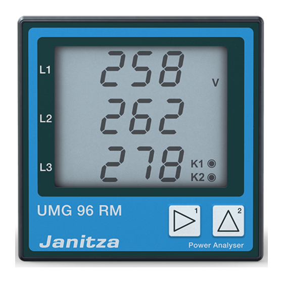
janitza UMG 96 RM-PN User Manual (128 pages)
Power Analyzer
Brand:
janitza
| Category:
Measuring Instruments
| Size: 2 MB
Table of Contents
Connection Example
2
Table of Contents
2
Table of Contents
4
General Information
4
Inspection on Receipt
6
Available Accessories
7
Product Description
8
Proper Use
8
UMG 96RM-PN Features
10
Measuring Process
11
Operating Concept
11
Gridvis Network Analysis Software
11
Connection Variants
12
Assembly
13
Installation
15
Supply Voltage
15
Voltage Measurement
16
Current Measurement Using I1 to I4
22
Analogue Inputs
30
Residual Current Monitoring (RCM) Via I5, I6
31
Thermistor Input
33
RS485 Interface
34
Ethernet / Profinet Interface
37
Digital In-/Outputs
39
LED Status Bar
44
Operation
45
Display Mode
45
Programming Mode
45
Parameters and Measured Values
47
Configuration
49
Connecting the Supply Voltage
49
Current and Voltage Transformer
49
Programming the Current Transformer for I1-I3
51
Programming the Voltage Transformer
52
Programming Parameters
53
TCP/IP Configuration
54
RS485 Device Address (Addr. 000)
56
RS485 Baud Rate (Addr. 001)
56
User Password (Addr. 050)
57
Parameters
58
Mean Value
58
Averaging Method
58
Min. and Max. Values
58
Mains Frequency (Addr. 034)
59
Power Meters
60
Resetting Energy Meters (Addr. 507)
60
Harmonics
61
Measured Value Rotation
62
Measured Value Screens
62
Direction of the Rotating Field
64
LCD Contrast (Addr. 035)
64
Backlight
64
Time Logging
66
Operating Hours Counter
66
Total Running Time, Comparator
66
Serial Number (Addr. 754)
67
Software Release (Addr. 750)
67
Commissioning
68
Connecting the Supply Voltage
68
Connecting the Measured Voltage
68
Applying the Measuring-Circuit Voltage
68
Direction of the Rotating Field
69
Checking the Phase Assignment
69
Checking the Power Measurement
69
Applying the Residual Current
69
Failure Monitoring (RCM) for I5, I6
70
Checking the Measurement
71
Checking the Single Phase Powers
71
Checking the Sum Powers
71
RS485 Interface
72
Digital Outputs
74
Digital Output Status Indicators
75
Pulse Output (Group 1)
77
Comparators and Threshold Value Monitoring
82
Service and Maintenance
88
Service
88
Device Calibration
88
Calibration Intervals
88
Firmware Update
89
Error / Warning Messages
90
Technical Data
96
Function Parameters
103
Table 1 - Parameter List
105
Table 2 - Modbus Address List
112
Number Formats
115
Dimension Diagrams
116
Measured Value Screen Overview
118
Connection Example 1
124
Connection Example 2
125
Basic Functions Quick Guide
126
TCP/IP Addressing Quick Guide
127
Advertisement
Advertisement
Related Products
Janitza UMG 96 RM
janitza UMG96RM
janitza UMG 96 RM-P
janitza UMG 96RM-P
janitza UMG 96 RM-M
janitza UMG 96 RM-E
janitza UMG 96 RM-EL
janitza UMG 96
janitza UMG 96S 24V
janitza UMG 96-EL
janitza Categories
Measuring Instruments
Control Unit
Controller
Monitor
Touch Panel
More janitza Manuals
Login
Sign In
OR
Sign in with Facebook
Sign in with Google
Upload manual
Upload from disk
Upload from URL