Risco WisDom Installation And Programming Manual
Hide thumbs
Also See for WisDom:
- User manual (64 pages) ,
- User manual (68 pages) ,
- Installation and programming manual (152 pages)
Table of Contents
Advertisement
Advertisement
Table of Contents

Related Manuals for Risco WisDom


Summary of Contents for Risco WisDom
- Page 1 Installation and Programming Manual...
- Page 3 Installation and Programming Manual (Ver 4.31 and above)
-
Page 5: Table Of Contents
Jumpers Setting............................2-11 Adjusting the LCD Contrast ........................2-12 Chapter 3: Programming the WisDom.................3-1 WisDom Programming Options........................3-1 Using the WisDom’s LEDs and Keys ......................3-2 Engineer Programming from the WisDom Keys ..................3-3 Accessing the Engineer Programming Menu .....................3-4 Restoring Manufacturer's Programming Defaults..................3-5 Keypad Timeout............................3-6 Using the Program Transfer Module (PTM) ....................3-7... - Page 6 Report Codes: Manual Codes ........................4-73 Alarm Receiving Station: Voice Alarm Verification..................4-82 Key-fobs ...............................4-83 Key-fobs: Allocation...........................4-83 Key-fob: Parameters..........................4-84 Key-fob: Communication Test........................4-85 Keypads ...............................4-86 Keypads: Allocation ...........................4-86 Keypads: Communication Test ........................4-87 More Devices ...............................4-88 More Devices: GSM ..........................4-88 WisDom Installation and Programming Manual...
- Page 7 Report Code Programming for SESCOA SUPERFAST (03B1) ..............A-1 Report Code Programming for ADEMCO POINT (CONTACT) ID (0420) ..........A-2 Report Code Programming for SIA (0700) ....................A-3 Appendix B: Event Log Messages..................B-1 Appendix C: EN50131 Default Values..................C-1 Appendix D: WisDom Accessories..................D-1 WisDom Installation and Programming Manual...
- Page 8 WisDom Installation and Programming Manual...
-
Page 9: Chapter 1: Introducing Wisdom
The WisDom has been specifically designed to meet a wide range of security needs of homes, offices and small commercial applications. The WisDom is simple and fast to install. It has a user friendly interface that enables easy installation, programming and use. In addition, the WisDom can also be programmed and/or controlled through local or remote Upload/Download software installed on a PC computer with a Windows operating system. -
Page 10: Wisdom Architecture And Capabilities
WisDom Architecture and Capabilities The following diagram provides an overview of the WisDom's architecture and capabilities. Examine this figure before beginning your WisDom installation to obtain an overall picture of the full extent of the WisDom system's capabilities. Figure 1-1: WisDom Architecture and Capabilities... -
Page 11: Wisdom Features
WisDom Features The following illustration describes the main features of the WisDom. Figure 1-2: WisDom Features WisDom Installation and Programming Manual... -
Page 12: Technical Specifications
Technical Specifications The following technical specifications are applicable for the WisDom: Electrical Characteristics System Power 230/120VAC, External Transformer 1500mA, 9VAC Current Consumption 140 mA minimum / 1200 mA maximum (Standby / Maximum) Backup Battery 6 x 1.5VDC Size AA, Alkaline 6 x 1.2V Size AA, rechargeable cells... -
Page 13: Chapter 2: Installing The Wisdom
Chapter 2: Installing the WisDom This chapter covers the installation procedures of the WisDom, as follows: WisDom Installation Steps, below ♦ WisDom Components, page, 2-2 ♦ Mounting the WisDom, page 2-2 ♦ Wiring the WisDom, page 2-6 ♦ WisDom Installation Steps The following workflow illustrates the recommended method for installing the WisDom. -
Page 14: Wisdom Components
WisDom Components The illustration below shows the internal components when the front panel is separated from the back plate. Figure 2-1: WisDom Internal components Layout 1. Back panel 9. Tamper spring 17. Internal sounder / buzzer 2. Tamper housing 10. Default jumper (J9) 18. -
Page 15: Mounting The Wisdom
Mounting the WisDom Choosing the mounting location Before you mount the WisDom, study the premises carefully in order to choose the exact location of the unit for the best possible coverage and yet easily accessible to prospective users of the alarm system. - Page 16 3. Pull the WisDom battery housing outward (See figure 2-1) 4. Release the back panel holding tabs (see Figure 2-3) located on both sides of the PCB and pull out the PCB gently. Figure 2-3: Releasing the PCB 5. Hold the back panel against the wall as a template and mark the locations for the mounting holes (6 mounting holes are available).
- Page 17 10. Connect the desired wires to the back panel’s terminal block as illustrated in the WisDom Wiring Diagram on page 2-6. 11. If desired, before closing the unit: Set the jumpers as described on page 2-11. Set the LCD contrast as described on page 2-12.
-
Page 18: Wiring The Wisdom
This step explains the various wiring and connection procedures that must be performed when wiring the WisDom, as follows IMPORTANT: Before wiring the WisDom, ensure that the connection to the power supplies, mains or battery, is switched OFF. Figure 2-6: WisDom Wiring Diagram... -
Page 19: Wiring The Bell Tamper
4-10 Wiring the Programming Outputs The WisDom includes 4 programming outputs (2 x 24VDC 3Amps relays, 2 x 13.8 VDC 70 mA transistor outputs). These outputs help operate external devices in response to a number of system activities related to alarms, zones, partitions, general system events, actions of particular user or scheduled events based on the system’s internal clock. -
Page 20: Ground Connection
It may be possible to use an existing electrical ground on the premises if one is close enough to the WisDom. When connecting the ground wire, use a solid 14-gauge wire [or larger (numerically lower) size]. Keep this wire as short as possible and do not run it in conduit, coil it, bend it sharply, or run it alongside other wiring. -
Page 21: Wiring The Hardwire Zone
Wiring the Hardwire Zone The WisDom supports 1 hardwire zone - Zone 33 which can be used for example to connect a key switch. Connect this zone using twisted–pair or 4-conductor cable wiring. The following diagram illustrates the various zone connections: NOTE: The hardwire zone cannot be used as a fire zone. -
Page 22: Auxiliary Terminal
10 seconds before you reconnect any load to the auxiliary output. Wired Expansion Bus Modules (Optional) The WisDom includes provision for wiring of optional expansion modules. This refers to the set of 4 terminals located on the terminal block marked as AUX RED, COM BLK, BUS YEL and BUS GRN. -
Page 23: Jumpers Setting
Jumpers Setting The WisDom is equipped with internal jumpers. Use the following table to configure the jumpers according to the desired configuration: Jumpers on Position Function front panel Enables to default the panel and restore the WisDom to the manufacturers default settings. -
Page 24: Adjusting The Lcd Contrast
Adjusting the LCD Contrast The WisDom includes a trimmer located on the PCB of the front panel, next to the default jumper (see figure 2-1) that enables you to adjust the brightness and contrast of the LCD display. It is recommended to adjust the LCD display after powering up the system but prior to reattaching the two sub-assemblies when closing the unit. -
Page 25: Chapter 3: Programming The Wisdom
Program Transfer Module (PTM): (p/n RP128EE0000A) The PTM is a tiny circuit board ♦ into which a copy of the WisDom's configuration can be copied and stored as well as transferred to any installation when temporarily plugged into the 4-wire BUS connector. -
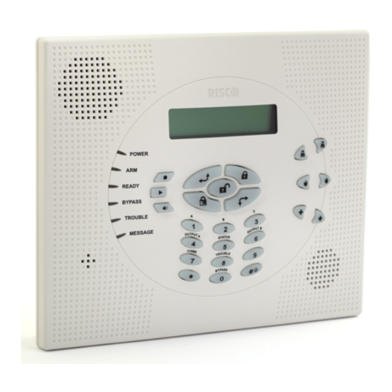
Page 26: Using The Wisdom's Leds And Keys
Using the WisDom’s LEDs and Keys Figure 3-1: The WisDom Surface The WisDom surface contains six LED indicators, an LCD display and a variety of keys. The LEDs have a different indication during programming mode than in normal operation mode. -
Page 27: Engineer Programming From The Wisdom Keys
This key does not function during programming operations Engineer Programming from the WisDom Keys This section explains how to use the WisDom keys to access the Engineer Programming menu as well as how to restore the manufacturer's defaults, as described in the following... -
Page 28: Accessing The Engineer Programming Menu
Accessing the Engineer Programming Menu This section describes how to access the Engineer Programming menu after the WisDom has been defaulted, as well as how to access it from the regular operation mode. To access the Engineer Programming Menu: 1. When you power up the system for the first time, the display of the regular operation... -
Page 29: Restoring Manufacturer's Programming Defaults
Enable) 2. Disconnect all power from the WisDom. 3. Open the WisDom unit and position the default jumper J9, located on the PCB of the front panel, on both pins. WisDom Installation and Programming Manual... -
Page 30: Keypad Timeout
4. Reconnect the power to the WisDom. All the LEDs flash once and a long beep is heard. The following message is displayed: WisDom: WisDom: --:-- ..--:-- ..NOTE: The Omit LED is ON as long as the default jumper (J9) is on both pins . -
Page 31: Using The Program Transfer Module (Ptm)
The Program Transfer module (PTM) is used to create and apply standard programming templates. In addition, you can use the PTM on powered-up, properly functioning WisDom , which have been previously programmed. To create a Programming Template by copying from a programmed WisDom: Use a programmed WisDom system to create a Programming Template to be applied to ♦... - Page 32 4. Restore power to the WisDom. After a moment, the LED on the Program Transfer module flashes rapidly, indicating that the information is being copied from the PTM to the WisDom system. The LCD keypad displays the following: PLEASE WAIT ...
-
Page 33: Chapter 4: Using The Engineer Programming Menus
Chapter 4: Using the Engineer Programming Menus This chapter describes the WisDom’s Engineer programming options and functions, as well as all quick key shortcuts. They are presented in a table of menus are listed according to their number, as follows:... -
Page 34: System
1. Access the Engineer Programming menu and select the main menu option that you want to access (refer also to Chapter 3, Programming the WisDom). 2. Press the Quick Keys listed in sequence (from left to right) to locate the option listed in the... - Page 35 Specifies a time period that starts when an alarm is triggered for the first time. If a second alarm is triggered before the end of the confirmation time window, the WisDom will send a confirmed alarm to the Monitoring Station. NOTE: Reopening the first zone for sequential alarm during the confirmation time window will reset the timer.
-
Page 36: System: Parameters
If any of the accessories does not respond to the request, at least once, during the supervision time of the WisDom receiver (Quick Key [1][3][3] ) the WisDom will regard the accessory as Lost. - Page 37 YES: If an alarm occurs when the system is set in the Part Set mode, a buzzer sounds for 15 seconds before the sounders operate. NO: An alarm in the Part Set mode causes sounders to operate simultaneously. WisDom Installation and Programming Manual...
- Page 38 NO: No Abort Alarm Code can be sent once an alarm has been triggered. Summer/Winter Clock YES/NO YES: The WisDom automatically sets its Time of Day clock one hour ahead in the spring (on the last Sunday in March) and one hour back in the Autumn (on the last Sunday in October).
- Page 39 Partition 2 is disarmed. Partition 3 is in ALARM mode. NO: The WisDom calls a pager during an alarm situation only in the partition for which it is programmed as a Follow-Me device. There are no enhancements to the standard message.
- Page 40 YES: For any partition(s) set up for Auto Setting, an audible Exit Delay (warning) countdown will commence 4.25 minutes prior to the automatic Setting. (Refer to the user's Automatic Setting function in the WisDom User's Manual for additional details.) During this period, Exit Delay beeps will be heard.
- Page 41 Exit/Entry Delay time of any set partition. NO: Specifies that all zones (that are programmed to follow an Entry Delay time) will follow the Entry Delay time of only the partitions to which they are assigned. WisDom Installation and Programming Manual...
- Page 42 ♦ External Bell YES/NO YES: Use this option when an external sounder is connected to the WisDom. The WisDom supervises the Bell (+)(-) terminals and BELL TMP COM terminals and announces faults, events, alarms and reports. To avoid Bell loop fault, if no connection is made to the Bell (+)(-) terminals, use a Ω...
- Page 43 WisDom will attenuate the receiving level of the WisDom by 6dB. 1. Prior to setting, the WisDom will not check whether a zone did not send a signal for more than 20 minutes 2.
- Page 44 NOTE: Sequential confirmation can still be established from two confirmed zones, located off the entry route. NO: The entry route zones will participate in the alarm confirmation process when the entry time starts. 4-12 WisDom Installation and Programming Manual...
-
Page 45: System: Receiver
NO: The system can be unset during any time using any unsetting device. NOTE: 1. If the system is set (not on the entry time), the system can't be unset with a keyfob. 2. Unsetting the system, while the parameter is defined as YES, from the WisDom keys, is disabled. System: Receiver The Receiver menu contains parameters that control the WisDom receiver. - Page 46 Specifies the period of time that the WisDom's receiver tolerates unwanted radio frequencies capable of blocking (jamming) signals produced by the system's transmitters. Once the specified time is reached, the WisDom sends a Report Code to the Central Station. (Refer to Jamming Fault, page 4-78.)
-
Page 47: System: Clock
Sets the current TIME (in 24-hour format). System Date JAN 01 2009 (SUN) MM DD YYYY (DAY) Sets the current DATE. (Refer to Chapter 3, Programming the WisDom, for instructions for using the keypad.) WisDom Installation and Programming Manual 4-15... -
Page 48: System: Labels
Use the keys on the keypad to produce characters according to the table below. Pressing a particular key, toggles between the characters available from that key in the sequence listed below followed by a blank space. The WisDom permits a total of 74 characters (letters, numbers, and symbols) for use in labelling. - Page 49 5. Press the [6], [7], [8], [9], or [0] key to create a space and press the key to advance the cursor. 6. Press the [1] key until a J appears. 7. Use the elements of this procedure to assign the remaining Partition Labels. WisDom Installation and Programming Manual 4-17...
-
Page 50: System: Sound
System: Sound The Tamper Sound menu contains parameters that enable you to set the sound(s) that will be produced by the WisDom after a Tamper violation of a zone, the WisDom box, wireless keypad or any other device. To access the Tamper Sound menu: 1. -
Page 51: System: Defaults
Range: Enable/Disable The Default jumper parameter relates to what happens if the DEFAULT (J9) Jumper is in place when power to the WisDom is switched off and then on. To access the Defaults jumper menu option: Access the System menu, as described on page 4-2. -
Page 52: System: Version
1. Access the System menu, as described on page 4-2. 2. From the System menu, press [9] to access the System Version menu option. The system version with the software's checksum number is displayed. 4-20 WisDom Installation and Programming Manual... -
Page 53: Zones
2. From the Zones menu, press [1] to access the Allocation menu options. 3. Specify a two-digit zone number intended for the first wireless transmitter and press The following display appears: Zone:xx Zone:xx (Alloc) (Alloc) 1)Skip 1)Skip WisDom Installation and Programming Manual 4-21... -
Page 54: Zones: Parameters
Re (Write) Overwrite the data into the selected location and allocate the transmitter to a zone (within 255 seconds), according to the instructions supplied with each transmitter. If the WisDom successfully recognizes the transmitter it will sound a confirmation beep. Erase Erase the allocation data in the selected location and then press [Y] YES or [N] NO to confirm your choice (Default: NO). - Page 55 One by One programming mode. Zone 33 (Wired zone) Zone 33 is defined in the WisDom as a wired zone. Therefore, during the One By One option it has two additional parameters which follow the sound definitions and apply only for this wired zone: ♦...
-
Page 56: Zone Labels
The XX in the Z=XX designation refers the zone number. In a multi-partitioned system, a zone can be assigned to more than one partition. A system without partitions is regarded as having a single partition (meaning Partition 1 ). 4-24 WisDom Installation and Programming Manual... -
Page 57: Zone Type
This zone behaves as described in the Exit/Entry 1 parameter, shown above, except that, if faulted when the system is being set, it does NOT prevent Setting . To avoid an intrusion alarm, it must be secured before the expiration of the WisDom Installation and Programming Manual 4-25... - Page 58 Default for zone 2 Usually assigned to motion detectors and to interior doors protecting the area between the entry door and the WisDom. When violated, it will cause an intrusion alarm and ARC notification during the Entry Delay periods, according to the standard definitions.
- Page 59 Zone Fault. (Refer to Report Codes: Miscellaneous, page 4-74) 24 Hours Usually assigned to protect non-movable glass, fixed skylights, and cabinets (possibly) for shock detection systems. A violation of such a zone causes an instant intrusion alarm, regardless of the system's state. WisDom Installation and Programming Manual 4-27...
-
Page 60: Final Exit
When setting the system, the related partition sets 10 seconds after this zone is closed or opened and then closed. After it is triggered once, the zone acts as an Exit (Open)/Entry 1 zone. 4-28 WisDom Installation and Programming Manual... - Page 61 Entry Delay period. Keyswitch Delay Used to apply the Exit/Entry Delay 1 parameter to the momentary keyswitch operation. Latch KSW Delay Used to apply the Exit/Entry Delay 1 parameter to the latched keyswitch WisDom Installation and Programming Manual 4-29...
- Page 62 If the system is SET, only the bell sounders will produce the alarm. ♦ (BELL/S BUZZER/U) (Bell /Set Buzzer/Unset) In a case of alarm, the following occurs: In Unset mode, only the buzzer will operate. ♦ In Set mode, only the bell will operate. ♦ 4-30 WisDom Installation and Programming Manual...
-
Page 63: Zones: Testing
To access the Testing menu: 1. Access the Zones menu, as described on page 4-21. 2. From the Zones menu, press [3] to access the Testing menu options. The following display appears: Zone testing: Zone testing: 01)WL.comm.test 01)WL.comm.test WisDom Installation and Programming Manual 4-31... - Page 64 01)Zone 01 2. In order to proceed, initiate a transmission from the selected zone. A number between 00-99 indicates the strength of the signal between the transmitter and the WisDom. A successful test will be followed by a confirmation beep. NOTE: For more successful communication the strength of the signal should be higher than the receiver’s noise threshold level (see page 4-14)
-
Page 65: Zones: Editing
3. Confirm your choice by selecting either [Y] YES or [N] NO and pressing 4. Press the key to exit. The process is executed as the display is changed. WisDom Installation and Programming Manual 4-33... -
Page 66: Zones: Crossing
This type of linking is used with motion detectors in hostile or false-alarm prone environments. NOTE: The WisDom allows 10 unique sets of zone links (pairs of zones), which can be manually specified, as required. To access the Zone Crossing menu: 1. Access the Zones menu, as described on page 4-21. -
Page 67: Zones: Alarm Confirmation
You may want to establish a number of zone links, but leave them deactivated at this time (see below). 5. Press to determine how the WisDom will process violations of the paired zones. 6. Access and configure the paired parameters in the Zone Crossing menu, as follows:... - Page 68 Confirm Zones Define which zones will be defined for alarm sequential confirmation. When the first zone goes into alarm the WisDom transmits the first zone alarm. When the second zone goes into alarm, during the confirmation time, the panel transmits the zone alarm and the Police code.
-
Page 69: Programmable Outputs
Programmable Output, as well as the manner in which the output will be applied. In addition you can assign the outputs that will be activated by the user using the quick function key operation. The WisDom supports up to 20 outputs. Outputs 1-4 are located on the main board ♦... - Page 70 Programmable Output will be activated after the delay time. (Refer to Phone Line Cut Delay Time, page 4-3.). 2. When the GSM module is connected to the WisDom, the Line Fault output is activated when there is a loss of phone line simulation connection between the GSM Module and the WisDom (meaning there is both GSM and PSTN loss).
- Page 71 The Programmable Output will follow the predefined time programming that is defined in the scheduler of the weekly programs for Programmable Output activation. For additional details, refer to the WisDom User's Manual. Chime Follow Activates the Programmable Output following a chime sound.
- Page 72 Activates the Programmable Output when a DURESS alarm is initiated at the keypad related to the selected partition(s). To deactivate this Programmable Output in a latch pattern, refer to the User menu option Duress Reset ([2][6]) (described in the WisDom User's Manual). Buzzer Follow...
- Page 73 Activates the Programmable Output when the selected zone causes an alarm. Set Follow Activates the Programmable Output when the selected zone is set by the system. Unset Follow Activates the Programmable Output when the selected zones are unset. WisDom Installation and Programming Manual 4-41...
- Page 74 Programmable output that follows Zone or Partition event) 3. Press and set the deactivation by choosing ALL or ANY. ( Only for Programmable output that follows Zone or Partition event) 4. Press and choose a label. 4-42 WisDom Installation and Programming Manual...
- Page 75 The final step of defining an output is defining a label. You can create and/or edit a 10- character label description for each Programmable Output. Refer to Entering a New Label Using the LCD Keypad, page 4-16, for additional details. WisDom Installation and Programming Manual 4-43...
-
Page 76: Programmable Outputs: Output A
Programmable Outputs: Output A The Programmable Outputs: Output A menu defines which output will be activated, by the user, when using the key functions key [4] from the WisDom keys. To access the Output A menu: 1. Access the Outputs menu. -
Page 77: Code Maintenance
In addition, the WisDom contains the following special codes: Grand Master Code: Used by the system's owner. ♦ Engineer Code: Used by the WisDom installation company technician to program the ♦ system. The default Engineer Code is : [0][1][3][3] Sub-Engineer Code: Used by a technician sent by the WisDom installation company ♦... -
Page 78: Authority Levels
The User has access to the following: Setting and disarming Omitting zones Accessing designated partitions Viewing system status, fault , and alarm memory Activating designated Programmable Outputs 4-46 WisDom Installation and Programming Manual... -
Page 79: Codes: Partition
7. Repeat steps 2 to 6, as required, until all User Codes used in the system are assigned to the appropriate partition(s). 8. When you have completed the process, press the key to return to the previous level. WisDom Installation and Programming Manual 4-47... -
Page 80: Codes: Grand Master
3. Enter the new code, using the keypad's [0 to 9] keys and press 4. Confirm your selection by re-entering the same code and pressing 5. Press the key to return to the previous level. 4-48 WisDom Installation and Programming Manual... -
Page 81: Codes: Sub-Engineer
To use the Sub-Engineer's code: 1. From the normal user's display, enter the Partial Programming option by pressing [9] [2]. 2. Enter the Sub-Engineer's Code and press . The Sub-Engineer now has limited access to Engineer programming parameters. WisDom Installation and Programming Manual 4-49... -
Page 82: Codes: Code Length
For EN 50131 requirements: To comply with EN 50131 requirements a minimum number of code combinations is required, therefore the code length (quick key [4][6]) definition changes. See Appendix C: EN50131 Default Values for more information. 4-50 WisDom Installation and Programming Manual... -
Page 83: Digicom
You are now in the Digicom menu and can access the required submenus, as described in the following sections. Digicom: ARC Link - Up The WisDom version 4.xx enables to report events to the ARC in 3 connectivity (link-up) options: Voice, SMS or GPRS. The WisDom supports three ARC links (Quick key [5][1][1] to [5][1][3]). - Page 84 GPRS). PSTN/Voice Up to 32 alphanumeric characters The WisDom reports the ARC over the voice channel (PSTN or GSM). Press [1] and type in up to 32 digits. Include dialling prefixes and area code or special letters. When finished press If required, you can include the following special functions in the phone number to achieve the effect listed in the table.
-
Page 85: Digicom: Customer Account Numbers
To send an account number with less than 6 digits use the “0” digit, for example: For account number 1234 enter 001234. In this case the WisDom will not send the “0” digit to the central station. To send the “0” digit located at the left side of the number use the “A” digit instead of the “0” digit. For example, for account number 0407 enter A407, for 6 a digit account number 001207 enter AA1207. -
Page 86: Digicom: Arc Communication Format
Format for ARC Tel No. 3 0000 Defines the protocol format for the third ARC telephone number. Same as the option described above, except for the receiver connected to the third ARC Telephone Number. 4-54 WisDom Installation and Programming Manual... - Page 87 Sescoa, Super Fast, with Parity 4 + 3 + Parity 0331 Sescoa, Super Fast, with Parity + ETX 4 + 3 + Parity 03B1 ADEMCO Express 4 + 2+ Parity 0520 Sweden Robofon 0600 WisDom Installation and Programming Manual 4-55...
-
Page 88: Access Code
Parameter Default Access Code 5678 Enables you to define an Access Code that is stored in the WisDom. RISCO recommends using a different 4-digit Access Code for each installation. In order to enable communication between the Alarm Company and the... -
Page 89: Digicom: Controls
1. Press [3]. 2. Make a note of the 6-digit number for use in the Upload/Download software. Digicom: Controls The Controls menu contains parameters that enable you to control the WisDom Digicom operation. To access the Controls menu: 1. Access the Digicom menu, as described on page 4-50. - Page 90 NO: Event reports are sent immediately. Dial Tone YES: The WisDom waits a short (selectable) interval to detect a dial tone before dialling the ARC. (Refer to Dial Tone Time, page 4-61.) NO: The WisDom dials without waiting. Call Save...
- Page 91 Within one minute, the software calls again. ♦ ♦ The WisDom is programmed to pick up this second call on the first ring, thus bypassing any interaction with the answering machine. NOTE: This feature is used to prevent interference from an answering machine with remote Upload/Download operations.
-
Page 92: Digicom: Parameters
Show Kissoff YES: All LEDs on the WisDom light for one second when the Digicom receives the kissoff signal from the ARC's receiver. NO: The LEDS on the WisDom do not light upon receiving of the kissoff signal. Show Handshake YES: All LEDs on the WisDom light up for one second when the Digicom receives the handshake signal from the Central Station's receiver. - Page 93 Parameter Default Range ARC Retries 01 to 15 The number of times the WisDom redials the ARC after failing to establish communication. FM Retries 01 to 15 The number of times the Follow-Me phone number is redialed. 01 to 15...
-
Page 94: Periodic Test
Enter 00 to disable the swinger shutdown. Periodic Test The Periodic Test menu enables you to set the time period that the WisDom will automatically call the ARC or Upload/Download phone numbers in order to check the phone line connection. It also sends reports of non-urgent events, which reduces the number of calls made (only if the Call Save option is defined as YES). - Page 95 Used to schedule periodic Auto Batch download using the Upload/Download software. This is the day, time of day (in 24-hour format) and time interval at which the customer's WisDom automatically calls the alarm company's computer to download the Batch (selected parameters).
- Page 96 4. Press the key to return to the Digicom menu. More Enables to define more parameters of the WisDom Digicom Alarm Restore The Alarm Restore menu specifies under what conditions an Alarm Restoral is reported. This option informs the ARC of a change in the specified condition(s) during an alarm restore.
-
Page 97: Digicom: Arc Report Split
Y and N to define if the window is active for the given day. The window and the days chosen here also apply to the automatic Setting and Unsetting of the system. (Refer to the WisDom User's Manual for additional details.) Report Delay... - Page 98 1st Backup 2nd Reports non-urgent events (supervisory and test reports) to the ARC. Do Not Call Does NOT report non-urgent events to the ARC. Call 1st Reports non-urgent events to the 1st ARC Link-Up. 4-66 WisDom Installation and Programming Manual...
-
Page 99: Digicom: Follow-Me
2nd ARC Link-Up. Digicom: Follow-Me In addition to reporting to the ARC, the WisDom has a Follow-Me feature, in which a standard phone call, reporting a system event, is made to a designated phone number. This procedure is useful to alert a homeowner at work, or a business owner at home, of an alarm. - Page 100 Events Specifies which phone events will activate this Follow-Me number. NOTES: In a WisDom without voice capabilities, the Follow Me conveys a series of tones representing an active event. Events 19-25 can be reported as an SMS or E-mail. 1. Use the...
- Page 101 Events Restore Specifies which restore events will activate this Follow-Me number. NOTE: 1. This option is disabled on a WisDom without voice capabilities. 2. Events 10-14 can be reported as an SMS or E-mail only. 1. Use the keys to select the phone event from the list below, and then use the key to select [Y] YES or [N] NO.
- Page 102 Events are reported to the Follow Me number in SMS format. GSM E-mail Events are reported to the Follow Me destination by E-mail using the GPRS network. NOTE: Remember to define the GPRS parameters using quick key [9][1][4][3] 4-70 WisDom Installation and Programming Manual...
-
Page 103: Report Codes
Report Codes The Report Codes menu enables you to program the codes transmitted by the WisDom to report events (for example, alarms, fault s, restores, supervisory tests, and so on) to the ARC, as follows: The codes specified for each type of event transmission are a function of the ARC's own ♦... - Page 104 Any change in the system parameters requires you to reload the Auto Codes parameters in order to update the information that is being sent to the monitoring station. Delete All The WisDom resets to 00 all previously programmed Central Station Report Codes. This does not change any other programmed parameters.
-
Page 105: Report Codes: Manual Codes
1)Emergency 1)Emergency You are now in the Manual report Codes menu and you can access the required submenus for programming the many events codes supported by the WisDom, as described in the following sections: Report Codes: Manual Codes Quick Keys... - Page 106 Parameter Fire key To report a Fire Emergency. Duress key To report a Duress Emergency (refer also to the WisDom's User's Manual). Restore key Enter the 2-digit code used to report a restoral of the above keypad emergencies. Auxiliary Emergency (Special) key To report the restoral of an Auxiliary Emergency.
- Page 107 WisDom. AUX Fail Code to report a fault condition regarding the loss of Auxiliary Power (either continuous or switched) supplied by the WisDom. Clock Not Set Code to report a fault condition caused by a Clock Not Set. WisDom Installation and Programming Manual...
- Page 108 Code to report the restoring to normal of the telephone service to the WisDom. AC Loss Code to report the restoring to normal of the AC power supply to the WisDom. AUX Fail Code to report the restoring to normal of Auxiliary Power (either continuous or switched) supplied by the WisDom.
-
Page 109: Keyswitch Setting
A Report Code used when the system is Auto Set as a result of a previously scheduled user-determined event. NOTE: No specific user identification is possible. Refer to the WisDom User's Manual for additional details. Remote Setting A Report Code used when the system is Remotely Set as a result of actions performed by the ARC using its Upload/Download software. - Page 110 Report Code used when the system is Auto Unset by a previously scheduled event. NOTE: No specific user identification is possible. Refer to the WisDom User's Manual for additional details. Remote Unset Report Code for Remote Unsetting by the alarm company using its Upload/Download software.
- Page 111 A report code that indicates the following condition: If any of the sounders does not respond to any request from the WisDom, during the supervision time of the WisDom receiver (Quick Key [1][3][3] ), the WisDom will regard the sounder as Lost.
-
Page 112: Cancel Report
More More … Listen In Report code that informs the receiver at the ARC that the WisDom will automatically switch to Listen-In mode at the end of events transmission. For more information refer to ARC: Two Way Communication, below). Special... - Page 113 Network Quality, PIN code error, Module communication, GPRS password, GPRS IP fault, GPRS Connection, PUK code fault. Faults restore Report code that indicates that there are no troubles related to the GSM module. X-10 The X-10 report codes menu. WisDom Installation and Programming Manual 4-81...
-
Page 114: Alarm Receiving Station: Voice Alarm Verification
The Listen-In time period is defined as 2 minutes. Any press on the digit '1' during the Listen- In time will expand the time for an additional 2 minutes. If '1' is not pressed the WisDom will hang up the line after 2 minutes. During the Listen-In time period, the operator can switch to ‘Talk”... -
Page 115: Key-Fobs
Key-fobs The Key Fobs menu contains parameters that enable WisDom to allocate up to 8 rolling code Wireless key-fobs transmitters. The wireless key-fob transmitters (p/n RP128T4RC00A) are rolling code transmitters with the following options: Full set, Part set, Unset, Panic, and PO activation. -
Page 116: Key-Fob: Parameters
7. Set the parameters for the Panic Key #3 (used to perform a Panic or Programmable Output operation) from the following options: None: The button is disabled (default). Panic: The button is used to send a panic alarm. 4-84 WisDom Installation and Programming Manual... -
Page 117: Key-Fob: Communication Test
Key-fob: Communication Test The Key fob communication menu enables to perform a communication test between the key fob and the WisDom’s receiver. To access the Key – Fob Communication Test menu: 1. Access the Key - Fob menu, as described above. -
Page 118: Keypads
Keypads The Keypads menu contains parameters that enable WisDom to allocate the data it receives from the wireless keypads. Up to 2 wireless keypad can be added to the system. The wireless keypads are rolling code transmitters with the following options: Full Set,... -
Page 119: Keypads: Communication Test
Allow a few seconds for the receiver to react. A confirmation beep along with an OK message indicates a successful communication test . 5. Repeat the procedure to test an additional keypad or press to exit. WisDom Installation and Programming Manual 4-87... -
Page 120: More Devices
More Devices The More Devices menu contains parameters that enable the WisDom to expend its communication, signaling capabilities and enabling the security panel to support X-10 transmitters. GSM, below Sounder, page 4-94 X-10, page 4-97 More Devices: GSM The GSM /GPRS BUS module is a cellular communication module that can be used as a backup or a substitute to a normal PSTN line. - Page 121 NOTES: 1) Network loss is defined as RSSI level below the level defined in the minimum RSSI LEVEL parameter (Quick key [9][1][3][8]). 2) This parameter is relevant only for GSM/GPRS full version module. WisDom Installation and Programming Manual 4-89...
- Page 122 PBX Prefix A number dialled to access an outgoing line when the module is connected to a Private Branch Exchange (PBX) and not directly to a PSTN line. The WisDom enables to program two PBX numbers. Each PBX number can contain up to 6 numeric characters.
- Page 123 Configuring the module for such an operation requires programming the numbers and prefixes as described below: PBX prefix: "9" Prefix Constant: “052”, “054” (or “05” only) Prefix to remove: None Prefix to add: "03" Telephone numbers dialled the by GSM module: "039105555”, “0523664444”, “0543665555” WisDom Installation and Programming Manual 4-91...
-
Page 124: Smtp Password
The APN code differs from country to country and from one provider to another (the APN code is provided by your cellular provider). The WisDom supports an APN code field of up to 30 alphanumeric characters and symbols (!, &, ? etc). - Page 125 SMS was sent from, and compares them, to the last digits of the Follow Me telephone numbers defined in the WisDom. If the digits coincide, the number is recognized as one of the Follow Me numbers and the operation will be executed.
-
Page 126: More Devices: Sounder
The two-way Wireless Sounders are designed to extend the signalling capabilities of the WisDom wireless system within the protected area. The wireless Sirens offer an easy and flexible solution for quick installations. The sirens are powered by their own batteries and communicate wirelessly with the security panel using 868MHz frequency band. - Page 127 10 seconds to press on the tamper switch for at least 3 seconds. If the sounder is successfully recognized, the WisDom will sound a confirmation beep, the sounder will initiate a squawk sound and the 2 LEDs on the sounder will flash for 3 seconds.
-
Page 128: Alarm Volume
The sounder communication test performs a communication test between the sounder receiver and the WisDom. The value displayed indicates the receiving level of the signal sent from the WisDom to the sounder's receiver. To perform communication test: From the engineer menu access the sounder communication test submenu, Quick Key [9][2][3]. -
Page 129: More Devices: X-10
An ongoing tamper alarm will not be disabled. More Devices: X-10 The X-10 Adapter Module is a unique service component, which enables RISCO Group's security panels to activate X -10 devices. The X-10-adapter module converts the information sent from the programmable programming output into the X - 10 protocol. -
Page 130: Communication Test
A result of less than 100% means that there is a BUS connection problem (for example poor wiring or cabling located in harsh electrical environment). 4-98 WisDom Installation and Programming Manual... -
Page 131: Exit Programming
Data is saved Data is saved Please wait.. Please wait.. The WisDom returns to the normal user display. -OR- Discard your changes by using the key to change the [Y] YES to [N] NO on the display and then press The WisDom returns to the normal user display. - Page 132 4-100 WisDom Installation and Programming Manual...
-
Page 133: Chapter 5: Engineer Programming Within The User Programming Menu
Programming the Voice Messages This section describes how to customize the spoken messages that the WisDom announces when you access the system from a remote telephone, or heard locally on the premises. In addition, this section describes how to verify the voice messaging and how to enable Announcement messages to be sounded locally. -
Page 134: Voice Messages Types
2. Status message: Upon remote access of the system by initiating a call from a remote telephone or receiving a call from the system, the WisDom announces the current system status by playing a pre-recorded Status message. -
Page 135: Message Structure
1)Common msg. 1)Common msg. You can now program a voice message label for each of the following options: [1] Common Message [2] Zone Message (zones 1-16) [3] Partition Message [4] Programmable Output Message [5] Macro Message WisDom Installation and Programming Manual... - Page 136 9 seconds or less press the to stop recording. NOTE: Not pressing immediately after finishing recording your message might cause unwanted noises or a long silence in your message. 3. Press to return to higher programming level. WisDom Installation and Programming Manual...
- Page 137 19) Ground floor 34) Safe 05) Bedroom 1 20) Guest room 35) Second floor 06) Bedroom 2 21) Hall 36) Shop 07) Bedroom 3 22) Hallway 37) Side door 08) Child room 23) Kitchen 38) Stairs WisDom Installation and Programming Manual...
- Page 138 The table of options is the same as the one described in the Zone Labels section on page 5-5. The default partition messages are as follows: Partition 1: Main floor (Label 27) Partition 2: Upstairs (Label 43) Partition 3: Perimeter area (Label 33) WisDom Installation and Programming Manual...
- Page 139 Press # to stop Press # to stop rec. rec. Time:2 Time:2 Recording stops automatically after 2 seconds. If you finish your message in less than 2 seconds press the to stop recording. WisDom Installation and Programming Manual...
-
Page 140: Test Message
Test Message The Test Message menu enables to verify the operation of the WisDom’s voice capabilities locally or remotely (using a remote Follow-Me telephone number) To perform messages testing: 1. Access the Voice message menu. 2. Select [3] Test Message. The following display appears:... -
Page 141: Local Announcement Messages
Local Announcement Messages Upon event occurrence, the WisDom can announce the security situation to occupants of the premises by sounding a local Announcement message. This Announcement message can be enabled or disabled, per event. To Enable/Disable Announcement Message: 1. Access the Voice message menu. -
Page 142: Walk Test
Walk Test mode. “End of Test Mode” announcement message will be heard. Replacing Backup Batteries The WisDom has 6 backup batteries that are used in time of main power failure. The batteries can be of two types: Non rechargeable: Size AA, 1.5VDC Alkaline ♦... -
Page 143: Rechargeable Batteries
2. If the low battery fault is still on, follow the instructions described in replacing non- rechargeable batteries Non rechargeable batteries : Pull out the battery housing located on the WisDom’s rear side. IMPORTANT: Your engineer may have locked the battery case by an internal screw. In this case contact your engineer to replace the batteries 2. - Page 144 5-12 WisDom Installation and Programming Manual...
-
Page 145: Appendix A: Report Codes
Restore Alarm + Rest New Codes If a new code, not supported by the Main Panel is required, it can be added to the list using the 'SPECIAL' programming item (up to 30 additional codes). WisDom Installation and Programming Manual... -
Page 146: Report Code Programming For Ademco Point (Contact) Id (0420
System Reset Main Bell Fault Power Supply Fault BUS Communication Fault Line Fault Fire Fault Sensor Fault Set/Unset Out Of Window User Set/Unset (with User ID) User Set/Unset (Group No. + User ID) Auto Set/Unset WisDom Installation and Programming Manual... -
Page 147: Report Code Programming For Sia (0700
AC Restoral AC Fault Burglary Alarm Burglary Cancelled Burglary Alarm Restore Burglary Fault Restore Burglary Fault Burglary Test Automatic Closing ('+ Area Number') Forced Closing Close Area ('System has been partly set') Late Close Early Close WisDom Installation and Programming Manual... - Page 148 Medical Fault Restore Medical Fault Automatic Opening Cancel Report Open Area ('+ Area Number') Late Open Early Open Opening Report Unset from Alarm Opening Keyswitch Point Opening ('+ Zone or Point') Panic Alarm Panic Alarm Restore WisDom Installation and Programming Manual...
- Page 149 Receiver/Transmitter Communication Fail Bell Restoral Communication Restoral System (Transmitter/Receiver) Battery Missing Power Supply Fault (Transmitter/Receiver) Power Supply Restored (Transmitter/Receiver) System Battery Restoral Communication Fault (Transmitter/Receiver) System Battery Fault Missing Supervision Burglar Verification Auto Set Fail Listen-In Begin WisDom Installation and Programming Manual...
- Page 150 WisDom Installation and Programming Manual...
-
Page 151: Appendix B: Event Log Messages
Time is not set Clock set C=XX Time defined by user No. XX Com OK Sounder=X Communication OK between the WisDom and sounder X Comm. OK GSM Bus communication restore with GSM/GPRS module Comm OK PO=X Bus communication restore with X10 expander ID=X Conf. - Page 152 Fault in Fire Zone No. XXX Fire KP=XX Fire alarm from wireless keypad XX (keys 3 & 4) Fire main KP Fire alarm from the WisDom fire emergency keys Fire Z=XXX Fire alarm in zone No. XXX Foil ok Z=XXX Restore in foil (Day) Zone No.
- Page 153 Partition X set by wireless key-fob YY Set fail P=X Partition X did not complete the setting procedure Sndr=X Lost Rst The WisDom received a signal from sounder X after it has been regarded as lost WisDom Installation and Programming Manual...
- Page 154 Zone XX has failed in the Soak test Sounder=X Lost Sounder X is regarded as lost following supervision test Spec. main KP Special alarm from the WisDom emergency keys Special KP=XX Special alarm from the from wireless keypad XX (keys 7 & 8) Spk flt rs S=$...
-
Page 155: Appendix C: En50131 Default Values
Appendix C: EN50131 Default Values This appendix summarizes the adjustments made in the Wisdom programming to comply with EN50131 standards. Note that the WisDom UK panels comply with EN50131 standards by default. Quick Feature Programming Standard Compliance System: Timers Entry Delay... - Page 156 A report to the ARC will be delayed for 30 seconds in addition to the time defined under the Report Delay Timer (Quick key [5][7][0][3) to allow time for unsetting. Note: Report Delay Timer defines the Digicom time delay before reporting an alarm condition to the ARC. WisDom Installation and Programming Manual...
-
Page 157: Appendix D: Wisdom Accessories
Program Transfer Module RP296EBA BUS adapter (cable) used for local PC-based Uploading/Downloading operations RP128EUSB00A USB 232 + 9/25 pin converter + PR296EBA for local use to connect between a PC USB port and the WisDom BUS connector WisDom Installation and Programming Manual... - Page 158 Installation should be done by a qualified electrician and according to the country's national electrical codes. • Installation or usage of the product not according to the intended use as defined by RISCO Group and as described in the manuals can result in severe injury or even death. •...
- Page 159 RISCO Group Limited Warranty RISCO Group and its subsidiaries and affiliates ("Seller") warrants its products to be free from defects in materials and workmanship under normal use for 24 months from the date of production. Because Seller does not install or connect the product and because the product may be used in conjunction with products not manufactured by the Seller, Seller cannot guarantee the performance of the security system which uses this product.
- Page 160 Contacting RISCO Group RISCO Group is committed to customer service and product support. You can contact us through our website www.riscogroup.com or as follows: United Kingdom Tel: +44-161-655-5500 Tel: +1-631-719-4400 technical@riscogroup.co.uk support-usa@riscogroup.com Italy Brazil Tel: +39-02-66590054 Tel: +55-11-3661-8767 support@riscogroup.it support-br@riscogroup.com...
Need help?
Do you have a question about the WisDom and is the answer not in the manual?
Questions and answers