Table of Contents
Troubleshooting

Related Manuals for Branson DCX A Series


Summary of Contents for Branson DCX A Series
- Page 1 Original Instructions 100-412-197 - REV. 07 DCX A Power Supply I n s t r u c t i o n M a n u a l Branson Ultrasonics Corporation 41 Eagle Road Danbury, CT 06813-1961 USA (203) 796-0400 http://www.bransonultrasonics.com...
- Page 2 Copyright and Trademark Notice Copyright © 2015 Branson Ultrasonics Corporation. All rights reserved. Contents of this publication may not be reproduced in any form without the written permission of Branson Ultrasonics Corporation.
- Page 3 Foreword Congratulations on your choice of a Branson Ultrasonics Corporation system! The Branson DCX A Power Supply system is process equipment for the joining of plastic parts using ultrasonic energy. It is the newest generation of product using this sophisticated technology for a variety of customer applications. This Instruction Manual is part of the documentation set for this system, and should be kept with the equipment.
- Page 4 100-412-197 REV. 07...
-
Page 5: Table Of Contents
Models Covered..........14 Compatibility with other Branson Products ......16 Features. - Page 6 Chapter 8:Maintenance General Maintenance Considerations ....... . . 122 DCX A Power Supply Preventive Maintenance......124 Recommended Spare Stock .
- Page 7 List Of Figures Chapter 1:Safety and Support Figure 1.1 Safety-related Labels found on the DCX A Power Supply ....3 Chapter 2:Introduction Figure 2.1 The DCX A Power Supply (Horizontal) .
- Page 8 Chapter 8:Maintenance Figure 8.1 Reconditioning Stack Mating Surfaces ....... . 127 Figure 8.2 Interconnect Diagram .
- Page 9 Branson Contacts ........
- Page 10 Table 5.23 30 kHz System ..........76 Table 5.24 40 kHz System .
- Page 11 Table 8.13 Troubleshooting ..........137 Table 8.14 Troubleshooting Common Electrical Problems .
- Page 12 100-412-197 REV. 07...
-
Page 13: Chapter 1:Safety And Support
How to Contact Branson ........ -
Page 14: Safety Requirements And Warnings
This chapter contains an explanation of the different Safety Notice symbols and icons found both in this manual and on the product itself and provides additional safety information for ultrasonic welding. This chapter also describes how to contact Branson for assistance. -
Page 15: Figure 1.1 Safety-Related Labels Found On The Dcx A Power Supply
1.1.2 Symbols Found on the Product The DCX A Power Supply has several safety-related labels on it to indicate the presence of hazardous voltages inside the unit. Figure 1.1 Safety-related Labels found on the DCX A Power Supply 100-412-197 REV. 07... -
Page 16: General Precautions
General Precautions Take the following precautions before servicing the power supply: • Be sure the power switch is in the off position before making any electrical connections • To prevent the possibility of an electrical shock, always plug the power supply into a grounded power source •... - Page 17 These are designed for a wide variety of welding or processing applications. If the equipment is used in a manner not specified by Branson, the protection provided by the equipment may be impaired. Branson Ultrasonics Corporation designs and manufactures machines giving the first priority to safety precautions, to allow customers to use the machines safely and effectively.
-
Page 18: Warranty Statement, Disclaimer
Terms and Conditions of Sale, or contact your Branson representative. TERMS AND CONDITIONS OF SALE Branson Ultrasonics Corporation is herein referred to as the “Seller” and the customer or person or entity purchasing products (“Products”) from Seller is referred to as the “Buyer.”... - Page 19 Repair service at the customer site • Includes parts and labor at the customer site performed by a Branson technician. The customer is responsible for all travel-related charges Module trade-in: •...
-
Page 20: How To Contact Branson
How to Contact Branson Branson is here to help you. We appreciate your business and are interested in helping you successfully use our products. To contact Branson for help, use the following telephone numbers, or contact the field office nearest you (business hours from 8 a.m. to 4 p.m. -
Page 21: Returning Equipment For Repair
Branson representative, or the shipment may be delayed or refused. If you are returning equipment to Branson for repair, you must first call the Repair department to obtain a Returned Goods Authorization (RGA) number. (If you request it, the repair department will fax a Returned Goods Authorization form to fill out and return with your equipment). - Page 22 Before sending equipment for repair, record the following information and send a copy of it with the equipment. This will greatly increase Branson’s ability to address the problem. 1. Describe the problem; provide as much detail as possible. For example, is the problem...
-
Page 23: Table 1.2 Branson Contacts
1.5.3 Departments to Contact Call your local Branson Representative, or contact Branson by calling and asking for the appropriate department, as indicated in Table 1.2 Branson Contacts below. Table 1.2 Branson Contacts What you need help with or At this Phone... -
Page 24: Obtaining Replacement Parts
Obtaining Replacement Parts You can reach Branson Parts Store at the following telephone numbers: Branson Part Store Direct telephone number: 877-330-0406 Fax number: 877-330-0404 Many parts can be shipped the same day if ordered before 2:30 p.m., Eastern time. A parts list is found in... -
Page 25: Chapter 2:Introduction
Models Covered ......... 14 Compatibility with other Branson Products ....16 Features . -
Page 26: Models Covered
Models Covered This manual covers all models of the DCX A Power Supply. Table 2.1 Models Covered in this Manual Frequency Power Model Horizontal 101-132-1822 1250 W Vertical 101-132-1829 Horizontal 101-132-1823 20 kHz 2500 W Vertical 101-132-1830 Horizontal 101-132-1824 4000 W Vertical 101-132-1831 Horizontal... -
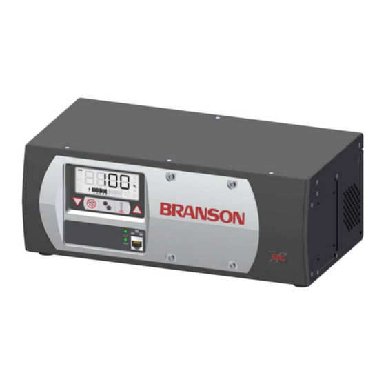
Page 27: Figure 2.1 The Dcx A Power Supply (Horizontal)
2.1.1 Overview of these Models Figure 2.1 The DCX A Power Supply (Horizontal) Figure 2.2 The DCX A Power Supply (Vertical) 100-412-197 REV. 07... -
Page 28: Compatibility With Other Branson Products
Compatibility with other Branson Products Table 2.2 Power Supply Compatibility with Branson Converters DCX A Model Converter CR-20 CR-20S 20 kHz / 1250 W CR-20C 20 kHz / 2500 W CH-20S 20 kHz / 4000 W CH-20C CS-20S CS-20C CR-30S... -
Page 29: Features
Listed below are the control features of the Branson DCX A Power Supply ultrasonic welding system • Autotuning: Branson power supply tuning ensures that the system is running at peak efficiency • Digital Amplitude Setting: This feature allows you to set the exact amplitude necessary for your application, allowing increased range and setting repeatability over analog systems •... - Page 30 • True Wattmeter: The controls on the power supply include a true wattmeter for accurate measurement of power and energy • Web Page Interface: Provides access, via Ethernet connection, to power supply information, diagnostics, and configuration web pages 2.3.3 The Actuator The DCX A Power Supply can interface with actuator signals.
- Page 31 The Horn The horn is selected or designed for a specific application. Each horn is tuned typically as a half-wave section that applies the necessary force and vibration uniformly to the parts to be assembled. It transfers ultrasonic vibrations from the converter to the workpiece. The horn is mounted to the booster as part of the ultrasonic stack.
-
Page 32: Controls And Indicators
Controls and Indicators 2.4.1 DCX A Power Supply Front Panel Figure 2.3 DCX A Power Supply Front Panel Controls and Indicators Table 2.3 DCX A Power Supply Front Panel Controls and Indicators Reference Description For detailed information refer to Figure 2.4 LCD Description Table 2.4 LCD Description. - Page 33 Table 2.3 DCX A Power Supply Front Panel Controls and Indicators Reference Description Configuration Key Use the Configuration key to change system registers. Registers are used to change system parameters. For information on using the Configuration key to set system registers see 7.4 Configuring the Power Supply Registers.
-
Page 34: Figure 2.4 Lcd Description
Figure 2.4 LCD Description Table 2.4 LCD Description Reference Description Numeric Display Displays the Power Supply amplitude settings, weld time settings, weld energy settings, peak power settings, scrub time settings, register numbers, register values or alarm numbers. Continuous Mode Icon Indicates the power supply is running in Continuous mode. - Page 35 Table 2.4 LCD Description Reference Description Peak Power Icon Indicates the power supply is running in Peak Power mode. When in Peak Power mode, the peak power percentage is shown on the numeric display in conjunction with the % icon. The peak power setting may range from 1% to 100% of the maximum power supply output power.
- Page 36 Table 2.4 LCD Description Reference Description Circle Icon Indicates that the value shown on the numeric display is a register value. Use up and down keys to modify the register value. For more information see 7.4 Configuring the Power Supply Registers.
-
Page 37: Figure 2.5 Dcx A Power Supply Back Panel (Horizontal)
2.4.2 DCX A Power Supply Connections Figure 2.5 DCX A Power Supply Back Panel (Horizontal) Figure 2.6 DCX A Power Supply Bottom Panel (Vertical) Table 2.5 Connections to the DCX A Power Supply Item Name Function Circuit Breaker / Turns the AC main power on or off. Power Switch Detachable connector block for connecting the input Line Input... -
Page 38: Welding Systems
Welding Systems 2.5.1 Principle of Operation Thermoplastic parts are welded ultrasonically by applying high frequency vibrations to the parts being assembled. The vibrations, through surface and intermolecular friction, produce a sharp rise in temperature at the welding interface. When the temperature is high enough to melt the plastic, there is a flow of material between the parts. -
Page 39: Glossary Of Terms
Glossary of Terms The following terminology may be encountered when using or operating a DCX A Power Supply ultrasonic welding system: Actuator: The unit which houses the converter/booster/horn stack assembly in a rigid mounting, allowing the stack to move up and down, either mechanically or pneumatically, applying force to the part at a user-adjustable force and velocity. - Page 40 Insertion: The process of embedding a metal component in plastic. Interface: 1. The contact surface of two mating parts. 2. The connection between two pieces of equipment. Joint: The weld surfaces. Parameter: A unique factor or element which affects the welding operation in a particular mode.
-
Page 41: Chapter 3:Delivery And Handling
Chapter 3: Delivery and Handling Shipping and Handling ........30 Receiving . -
Page 42: Shipping And Handling
Shipping and Handling CAUTION Heavy Object The power supply may be heavy. Handling, unpacking, and installation may require the assistance of a colleague or the use of lifting platforms or hoists. 3.1.1 Environmental Specifications The DCX A Power Supply is an electronic unit that converts line voltage to ultrasonic energy and responds to user input for regulating the weld process. -
Page 43: Receiving
Scope of Delivery Branson equipment is carefully checked and packed before dispatch. It is recommended, however, that you follow the procedure below upon receiving your DCX A Power Supply. Inspect the Power Supply when it is delivered, take the following steps: Table 3.2... -
Page 44: Unpacking The Power Supply
Unpacking the Power Supply NOTICE If there are any visible signs of damage to the shipping containers or the product, or you later discover hidden damage, NOTIFY YOUR CARRIER IMMEDIATELY. Save the packing material. The power supply is fully assembled. It is shipped in a sturdy cardboard box. Some additional items are shipped in the box with the power supply. -
Page 45: Take Inventory Of Small Parts
Take Inventory of Small Parts Table 3.4 Small Parts included: Power Supply Assemblies Part or Kit 20 kHz 30 kHz 40 kHz Mylar®* plastic film Washer Kit Silicone Grease Spanners (2) *Mylar is a registered trademark of DuPont Teijin Films. 3.4.1 Cables The RF cable connects the power supply to the converter. -
Page 46: Returning Equipment
Returning Equipment If you are returning equipment to Branson Ultrasonic Corporation, please call your Customer Service Representative to receive approval to return the goods. Refer to How to Contact Branson. 100-412-197 REV. 07... - Page 47 Chapter 4: Technical Specifications Technical Specifications ........36 Physical Description .
-
Page 48: 4:Technical Specifications
Technical Specifications NOTICE All specifications are subject to change without notice. 4.1.1 Environmental Specifications The DCX A Power Supply has the following environmental specifications: Table 4.1 Environmental Specifications Environmental Condition Acceptable Range Ambient Operating Temperature +41° F to +104° F (+5° C to +40° C) Storage / Shipping Temperature -13°... -
Page 49: Table 4.3 Input Current And Circuit Breaker Specifications
Input Current and Circuit Breaker Specifications Table 4.3 Input Current and Circuit Breaker Specifications Model Power Current Rating 1250 W 7 A Max. @ 200 - 240 V / 15 A Breaker 20 kHz 2500 W 14 A Max. @ 200 - 240 V / 25 A Breaker 4000 W 25 A Max. -
Page 50: Physical Description
Physical Description This section describes the physical dimensions of the DCX A Power Supply. NOTICE Dimensions are nominal. Table 4.5 Dimension and Weight of DCX A Power Supply Size Width Height Depth Weight Small 14” 5.5” (Benchtop) 356 mm 132 mm 7.4”... -
Page 51: Declaration Of Conformity
Declaration of Conformity Figure 4.1 Declaration of Conformity 100-412-197 REV. 07... - Page 52 100-412-197 REV. 07...
-
Page 53: Chapter 5:Installation And Setup
Chapter 5: Installation and Setup About Installation........42 Installation Requirements . -
Page 54: About Installation
About Installation This chapter is intended to help the installer with the basic installation and setup of your new DCX A Power Supply. CAUTION Heavy Object The power supply, and related components are heavy. Handling, unpacking, and installation may require the assistance of a colleague or the use of lifting platforms or hoists. -
Page 55: Installation Requirements
Installation Requirements This section covers the location requirements, mounting options, power supply dimensions, environmental requirements, and electrical requirements, to help you plan and execute your installation successfully. 5.2.1 Location The DCX A Power Supply comes in two different models Horizontal (benchtop) and Vertical (which may be back mounted or side mounted). -
Page 56: Table 5.1 Dcx A Power Supply Benchtop Dimensional Drawing
Figure 5.1 DCX A Power Supply Benchtop Dimensional Drawing Small 7.38 in (187.4 mm) 400 W - 800 W Medium 8.63 in (219.2 mm) 1250 W - 1500 W Large 10.63 in (270 mm) 2500 W - 4000 W 5.53 in (140.5 mm) 14.00 in (355.6 mm) - Page 57 Figure 5.2 DCX A Power Supply Vertical Mount Dimensional Drawing (400 W, 750 W and 800 W) 5.22 in (132.6 mm) 4.5 in 7.75 in (1143 mm) (196.8 mm) 3.5 in (89 mm) 17.38 in 15.75 in (441.5 mm) (400 mm) Back-mounted 7.38 in (187.4 mm)
-
Page 58: Figure 5.3 Dcx A Power Supply Vertical Mount Dimensional Drawing (1.25 Kw And 1.5 Kw)
Figure 5.3 DCX A Power Supply Vertical Mount Dimensional Drawing (1.25 kW and 1.5 kW) 5.22 in (132.6 mm) 4.5 in 9.0 in (114 mm) (229 mm) 3.5 in (89 mm) 17.38 in 15.75 in (441.5 mm) (400 mm) Back-mounted 8.63 in (219.2 mm) 2.62 in... -
Page 59: Figure 5.4 Dcx A Power Supply Vertical Mount Dimensional Drawing (2.5 Kw And 4 Kw)
Figure 5.4 DCX A Power Supply Vertical Mount Dimensional Drawing (2.5 kW and 4 kW) 5.22 in (132.6 mm) 4.5 in 11.0 in (114 mm) (279 mm) 3.5 in (89 mm) 17.38 in 15.75 in (400 mm) (441.5 mm) Back-mounted 10.63 in (270 mm) 3.62 in... -
Page 60: Table 5.5 Environmental Requirements
5.2.2 Environmental Requirements Verify the DCX A Power Supply is operated in an environment that meets the temperature and humidity requirements indicated in Table 5.5 Environmental Requirements. Table 5.5 Environmental Requirements Environmental Condition Acceptable Range Ambient Operating Temperature +41° F to +104° F (+5° C to +40° C) Humidity Maximum 95%, non-condensing IP Rating... -
Page 61: Installation Steps
Installation Steps WARNING High Voltage Hazard To prevent the possibility of an electrical shock: • Ensure the power source is disconnected before beginning work on line connections • Ensure the power switch on the back of the unit is in the OFF position before making any electrical connections •... - Page 62 Performance and results can suffer if the RF cable is crushed, pinched, damaged or modified. Contact your Branson Representative if you have special cable requirements. Do not place the power supply on the floor or in other locations that will allow dust, dirt or contaminants to be drawn into the power supply.
-
Page 63: Figure 5.5 Lcd Viewing Angle
5.3.4 Mounting Considerations In addition to the considerations mentioned above, the LCD’s viewing angle should be taken into account when selecting a location for your DCX A Power Supply. The LCD is designed to be viewed from the top. Please refer to Figure 5.5 LCD Viewing Angle below when selecting a location for your DCX A Power Supply. -
Page 64: Figure 5.6 Dcx A Power Supply Connections (Horizontal Model)
5.3.5 Electrical Connections Figure 5.6 DCX A Power Supply Connections (Horizontal Model) Table 5.7 DCX A Power Supply Connections (Horizontal Model) Item Description RF Connector Ground Screw RF Cable (Ferrite End) Ethernet Port User I/O Connectors Line Cord Circuit Breaker (On/Off Switch) Input Power Connector 100-412-197 REV. -
Page 65: Figure 5.7 Dcx A Power Supply Connections (Vertical Model)
Figure 5.7 DCX A Power Supply Connections (Vertical Model) Table 5.8 DCX A Power Supply Connections (Vertical Model) Item Description RF Connector Ground Screw RF Cable (Ferrite End) Ethernet Port User I/O Connectors Line Cord Circuit Breaker (On/Off Switch) Input Power Connector 100-412-197 REV. - Page 66 Table 5.14 Analog Output Functions list the input and output functions available on the DCX A Power Supply. Table 5.15 Default Branson User I/O Connector PIN Assignments, V6.0 for the default user I/O pin assignments. Figure 5.9 Typical Digital I/O Wiring Examples Figure 5.10 Typical Analog I/O Wiring...
-
Page 67: Figure 5.8 User I/O Cable Identification And Wire Color Diagram
Figure 5.8 User I/O Cable Identification and Wire Color Diagram User I/O Cable Stripped Jacket one end, HD-26 male connector other end (cable length as ordered) Wire Color Diagram Two Colors = Insulator/Stripe Three Colors = Insulator/Stripe/Dot Table 5.9 User I/O Cable Identification and Wire Color Diagram Item Description Part number... -
Page 68: Table 5.10 User I/O Cable Pin Assignments
5.3.7 User I/O Cable Pin Assignments Table 5.10 User I/O Cable Pin Assignments Input/Output Available Signal (All I/O are user Signal Range Color Function Type definable) Digital in 1* Table 5.11 Digital in 2* Discrete 0 V to 24 V +/- Digital Input 10%, 12 mA... - Page 69 Table 5.10 User I/O Cable Pin Assignments Input/Output Available Signal (All I/O are user Signal Range Color Function Type definable) Table 5.11 Discrete 0 V to 24 V +/- Digital in 9* Digital Wht/Blk/Red Input 10%, 12 mA Input Functions Analog out 1 Table Red/Blk/Wht...
-
Page 70: Table 5.11 Digital Input Functions
5.3.8 Digital Input Functions Table 5.11 Digital Input Functions Function Description ACT-Actuator Must be active at power up to activate TRS, ULS, Interlock, Part in Present Place. Will immediately terminate the current weld cycle and not accept ACT-Cycle Abort another External Start until removed. Reset required is user settable. Will start scrub time. - Page 71 Table 5.11 Digital Input Functions Function Description Delays the start of ultrasonics even if a trigger occurs. This can be used to enable an external operation to be complete before STD-External continuing the cycle (e. g. test device or part marking operation). If Sonics Delay the delay is maintained for 1 minute, the cycle is aborted and all inputs must be cycled again.
-
Page 72: Table 5.12 Digital Output Functions
5.3.9 Digital Output Functions Table 5.12 Digital Output Functions Function Description ACT-Actuator Indicates that a ULS input has been received. Home ACT-Afterburst Indicates if the weld cycle is in the Afterburst Delay state. Delay ACT-Afterburst Indicates if the weld cycle is in the Afterburst state. Time ACT-End of Hold Indicates the system has reached the end of Hold since the cycle... - Page 73 Table 5.12 Digital Output Functions Function Description STD-Plus Time Indicates the weld time did exceed the maximum time set. Limit Alarm STD-Plus Indicates the weld has exceeded the maximum peak power set. Peakpower Limit Alarm If active, indicates the system is ready to start a weld cycle, enter test mode, or start a horn scan.
-
Page 74: Table 5.13 Analog Input Functions
5.3.10 Analog Input Functions Table 5.13 Analog Input Functions Function Description Valid Range Controls the amplitude of ultrasonic 1 V to 10 V* Amplitude In energy that will be delivered by the power (10% to 100%) supply. Controls the frequency offset to the power supply operating frequency. -
Page 75: Table 5.14 Analog Output Functions
5.3.11 Analog Output Functions Table 5.14 Analog Output Functions Function Description Valid Range 0 V to 10 V Provides a 0 V to 10 V output signal proportional Amplitude Out to amplitude (0% to 100%). (0% to 100%) 0 V to 10 V Provides a 0 V to 10 V output signal proportional Power Out to ultrasonic power output (0% to 100%). -
Page 76: Table 5.15 Default Branson User I/O Connector Pin Assignments, V6.0
5.3.12 Default Branson User I/O Connector PIN Assignments Software V6.0 - V6.4 Table 5.15 Default Branson User I/O Connector PIN Assignments, V6.0 Function I/O Type Values Apply +24 VDC to run cycle STD-External Start Input Digital NOTICE DCX A Power Supply must be in ready mode before External Start. - Page 77 Table 5.15 Default Branson User I/O Connector PIN Assignments, V6.0 Function I/O Type Values +24 V indicates a load new preset STD-Confirm Preset Output request has occurred and the preset Change Digital was successfully recalled. +24 V must be present for...
-
Page 78: Table 5.16 Default Branson User I/O Connector Pin Assignments, V6.5
Software V6.5 or Newer Table 5.16 Default Branson User I/O Connector PIN Assignments, V6.5 Function I/O Type Values Apply +24 VDC to run cycle STD-External Start Input Digital NOTICE DCX A Power Supply must be in ready mode before External Start. - Page 79 Table 5.16 Default Branson User I/O Connector PIN Assignments, V6.5 Function I/O Type Values +24 V must be present for STD-Display Lock Input Digital ultrasonics to be enabled. Output Power Out 0 V to + 10 V (0% to 100%)
-
Page 80: Figure 5.9 Typical Digital I/O Wiring Examples
5.3.13 Typical Digital I/O Wiring Examples Figure 5.9 Typical Digital I/O Wiring Examples 5.3.14 Typical Analog I/O Wiring Examples Figure 5.10 Typical Analog I/O Wiring Examples 100-412-197 REV. 07... -
Page 81: Figure 5.11 Rf Cable Connection
5.3.15 Output Power (RF Cable) Connection Ultrasonic energy is delivered to the SHV connector on the power supply, which is then transmitted to the converter via the RF cable. The RF connector position depends on the power supply configuration. For Horizontal models it is located on the rear panel of the power supply. -
Page 82: Table 5.18 Input Power Connection
5.3.16 Input Power Connection WARNING High Voltage Hazard Ensure all electrical power is off when wiring input power to your DCX A Power Supply connector block. To prevent the possibility of an electrical shock, ground the power supply by securing an 8 gauge grounded conductor to the ground screw located next to the air outlet. - Page 83 Table 5.18 Input Power Connection Step Action Connect the converter-booster-horn stack to the power supply using the RF cable. See 5.3.15 Output Power (RF Cable) Connection. Ensure the power switch on the back of the unit is in the OFF position. Plug the connector block back into the power supply.
-
Page 84: Power Supply Setup
Power Supply Setup Certain power supply configurations can be modified from the factory setting if needed. Although not usually requiring modifications from the factory setting, the following features are selectable: • Afterburst: Allows for a short activation of ultrasonics at the end of the weld cycle to reliably release parts from the horn •... -
Page 85: Assembling The Acoustic Stack
(one) Mylar plastic film washer of the correct inside and outside diameters at each interface. NOTICE The use of a Branson torque wrench or the equivalent is recommended. P/N 101-063-787 for 20 kHz, and 30 kHz systems and 101-063-618 for 40 kHz systems. -
Page 86: Figure 5.12 Assembling The Acoustic Stack
Figure 5.12 Assembling the Acoustic Stack Acoustic Stack Description Table 5.19 Acoustic Stack Description Item Description Converter Booster Spanner (provided) Horn See stack assembly procedure Vise Jaw protectors (aluminum or soft metal) Vise 100-412-197 REV. 07... -
Page 87: Table 5.20 Stack Torque Values
Stack Torque Values Table 5.20 Stack Torque Values Frequency Torque 20 kHz 220 in·lb (24.85 N·m) 30 kHz 185 in·lb (21 N·m) 40 kHz 95 in·lb (10.73 N·m) Tools Table 5.21 Tools Tool EDP Number 20 kHz, and 30 kHz Torque Wrench Kit 101-063-787 40 kHz Torque Wrench 101-063-618... -
Page 88: Table 5.22 20 Khz System
5.5.1 For a 20 kHz System Table 5.22 20 kHz System Step Action Ensure that the mating surfaces of the converter, booster, and horn are clean, and that the threaded holes are free of foreign material. Install a single Mylar plastic film washer (matching the size of the washer to the stud) to each interface. -
Page 89: Figure 5.13 Connecting Tip To Horn
5.5.4 Connecting Tip to Horn 1. Ensure that the mating surfaces of the tip and horn are clean. Remove any foreign matter from the threaded stud and hole. 2. Hand assemble the tip to the horn. Assemble dry. Do not use any silicone grease. 3. -
Page 90: Converter Cooling
Converter Cooling Converter performance and reliability can be adversely affected if the converter ceramics are subjected to temperatures above 140° F (60° C). The converter front driver temperature should not exceed 122° F (50° C). To prolong converter life and maintain a high degree of system reliability, the converter should be cooled with clean, dry, compressed air, particularly if your application calls for continuous ultrasonic operation. -
Page 91: Table 5.27 Converter Cooling Procedure
If converter cooling is required, use the following steps: Table 5.27 Converter Cooling Procedure Step Action Start with a 50 psi (345 kPa) air source or higher from a 0.06 in (1.5 mm) I.D. orifice Perform a run of welding operations. Immediately after completing the welding run, check the converter temperature. -
Page 92: Testing The Installation
Testing the Installation To test the power supply follow the procedure described in 7.6 Ultrasonics Test Procedure Chapter 7: Operation. 100-412-197 REV. 07... -
Page 93: Still Need Help
Still Need Help? Branson is pleased that you chose our product and we are here for you! If you need parts or technical assistance with your DCX A Power Supply system, call your local Branson representative. Please refer to 1.4 How to Contact Branson for a list of Branson key contacts. - Page 94 100-412-197 REV. 07...
- Page 95 Chapter 6: Converters and Boosters Converters and Boosters ........84 100-412-197 REV.
-
Page 96: 6:Converters And Boosters
Converters and Boosters A variety of converters and boosters available for use with the DCX A Power Supply are illustrated in the following pages. WARNING High Voltage Hazard To avoid the possibility of electrical shock. Converters need to be properly grounded. NOTICE Special adaptor cables are available to connect to MS-style converters (CR20 and 4TR). -
Page 97: Figure 6.2 20 Khz Booster Dimensions
Table 6.1 20 kHz CH-20S Converter Dimensions Item Description Grip area Figure 6.2 20 kHz Booster Dimensions Table 6.2 20 kHz Booster Dimensions Item Description 1/2 - 20 x 1 - 1/4 stud (Ti boosters) 1/2 - 20 x 1 - 1/2 stud (Al boosters) Grip Ring Diameter Variable Varies with tuning and gain... -
Page 98: Figure 6.3 20 Khz Converter/Booster/Horn, Typical Dimensions
Figure 6.3 20 kHz Converter/Booster/Horn, Typical Dimensions Table 6.3 20 kHz Converter/Booster/Horn, Typical Dimensions Item Description Converter Booster One-half wavelength horn Recommended clamping area Booster front end diameter will vary with amplitude * Overall horn length can vary beyond these typical dimensions depending on the application. 100-412-197 REV. -
Page 99: Figure 6.4 30 Khz Converter Dimensions
Figure 6.4 30 kHz Converter Dimensions Table 6.4 30 kHz Converter Dimensions Item Description Air inlet SHV connector Ground stud Grip area CR-30S and CH-30S are dimensionally identical, and differ only in their respective cooling feature. CR-30S has flow through cooling, and CH-30S has closed loop cooling (air circulates in the converter and returns to its source). -
Page 100: Figure 6.5 30 Khz Booster Dimensions
Figure 6.5 30 kHz Booster Dimensions Table 6.5 30 kHz Booster Dimensions Item Description 3/8 - 24 x 1 - 1/4 stud Grip Ring Diameter Variable Varies with tuning and gain * These dimensions do not vary. 100-412-197 REV. 07... -
Page 101: Figure 6.6 30 Khz Converter/Booster/Horn, Typical Dimensions
Figure 6.6 30 kHz Converter/Booster/Horn, Typical Dimensions Table 6.6 30 kHz Converter/Booster/Horn, Typical Dimensions Item Description Converter Booster One-half wavelength horn Recommended clamping area Booster front end diameter will vary with amplitude * Overall horn length can vary beyond these typical dimensions depending on the application. 100-412-197 REV. -
Page 102: Figure 6.7 40 Khz, 4Tr Converter Dimensions
Figure 6.7 40 kHz, 4TR Converter Dimensions Table 6.7 40 kHz, 4TR Converter Dimensions Item Description Ground stud SHV connector Grip area 100-412-197 REV. 07... -
Page 103: Figure 6.8 40 Khz Booster Dimensions
Figure 6.8 40 kHz Booster Dimensions Table 6.8 40 kHz Booster Dimensions Item Description M8 x 1 - 1/4 stud (Ti boosters) M8 x 1 - 1/2 stud (Al boosters) Grip ring diameter Variable Varies with tuning and gain 100-412-197 REV. 07... -
Page 104: Figure 6.9 40 Khz Converter/Booster/Horn, Typical Dimensions
Figure 6.9 40 kHz Converter/Booster/Horn, Typical Dimensions Table 6.9 40 kHz Converter/Booster/Horn, Typical Dimensions Item Description Converter Booster One-half wavelength horn Recommended clamping area Booster front end diameter will vary with amplitude * Overall horn length can vary beyond these typical dimensions depending on the application. ** Dimension varies with tuning and gain. - Page 105 6.1.1 Component Functional Description Ultrasonic Stack Converter The converter is mounted in the customer's automation as part of the ultrasonic stack. The ultrasonic electrical energy from the power supply is applied to the converter (sometimes called the transducer). This transforms the high frequency electrical oscillations into mechanical vibrations at the same frequency as the electrical oscillations.
- Page 106 Solid Mount Boosters The solid mount booster is a one-half wave-length resonant section made exclusively of titanium. It is mounted between the converter and the horn, modifying the amplitude of vibration applied to the horn and providing a clamping point. The solid mount booster is superior to prior versions in that deflection is minimized.
-
Page 107: Chapter 7:Operation
Chapter 7: Operation Setting Primary Parameters ....... . 96 Setting the Amplitude........107 Resetting the Power Supply Alarms . -
Page 108: Setting Primary Parameters
After analyzing your specific application, you can determine the Weld Mode to use to weld your parts. A Weld Mode is a set of parameters that governs the weld. (Contact the Branson Ultrasonics Applications Laboratory for more information on determining the best mode for welding your application. See 1.4 How to Contact... -
Page 109: Table 7.2 Continuous Mode Operational Sequence
7.1.1 Setting Continuous Mode In this mode, ultrasonic energy will be delivered continuously while the start signal is present. Within Continuous Mode, you can also select several other parameters, ranging from afterburst to limits and cutoffs. For more information on setting the optional parameters within Continuous Mode, or any other welding mode, refer to the DCX A/F Series Web Page Instruction Manual. - Page 110 Table 7.2 Continuous Mode Operational Sequence Step Action Reference Use the Up/Down arrow keys to select value 0 (Continuous mode), then press the Configuration key to confirm the selection. Continuous mode icon and amplitude value will be displayed. 100-412-197 REV. 07...
-
Page 111: Table 7.3 Time Mode Parameters
7.1.2 Selecting Time Mode You can use Time Mode to select the length of time that ultrasonic energy is applied to your parts. Within Time Mode, you can also select several other parameters, ranging from afterburst to limits and cutoffs. For more information on setting the optional parameters within Time Mode, or any other welding mode, refer to the DCX A/F Series Web Page Instruction Manual. -
Page 112: Table 7.5 Setting Time Mode Parameters
Table 7.4 Selecting Time Mode Step Action Reference Use the Up/Down arrow keys to select value 1 (Time mode), then press the Configuration key to confirm the selection. 7.1.2.1 Setting Time Mode Parameters Table 7.5 Setting Time Mode Parameters Step Action Reference Set the Power Supply to Time Mode. -
Page 113: Table 7.6 Energy Mode Parameters
7.1.3 Selecting Energy Mode You can use Energy Mode to select the amount of ultrasonic energy that is applied to your parts. Within Energy Mode, you can also select several other parameters, ranging from afterburst to limits and cutoffs. For more information on setting the optional parameters within Energy Mode, or any other welding mode, refer to the DCX A/F Series Web Page Instruction Manual. -
Page 114: Table 7.8 Setting Energy Mode Parameters
Table 7.7 Selecting Energy Mode Step Action Reference Use the Up/Down arrow keys to select value 2 (Energy mode), then press the Configuration key to confirm the selection. 7.1.3.1 Setting Energy Mode Parameters Table 7.8 Setting Energy Mode Parameters Step Action Reference Set the power supply to energy mode. -
Page 115: Table 7.9 Peak Power Mode Parameters
7.1.4 Selecting Peak Power Mode You can use Peak Power Mode to select the maximum percentage of the total available power that will be used to process your welds. When the power level you set is reached, ultrasonics will be terminated. From within Peak Power Mode, you can also select several other parameters, ranging from afterburst to limits and cutoffs. -
Page 116: Table 7.11 Setting Peak Power Mode Parameters
Table 7.10 Selecting Peak Power Mode Step Action Reference Use the Up/Down arrow keys to select value 3 (Peak Power mode), then press the Configuration key to confirm the selection. 7.1.4.1 Setting Peak Power Mode Parameters Table 7.11 Setting Peak Power Mode Parameters Step Action Reference... -
Page 117: Table 7.12 Ground Detect Mode Parameters
7.1.5 Selecting Ground Detect Mode You can use Ground Detect Weld Mode to have ultrasonic energy turn off when the horn comes in contact with your electrically isolated fixture or anvil. Ground Detect is available with a scrub time range of 0.001 seconds to 0.500 seconds. From within Ground Detect Mode, you can also select several other parameters, ranging from Hold Time (in seconds) to Suspect and Reject Limits. -
Page 118: Table 7.14 Setting Ground Detect Mode Parameters
Table 7.13 Selecting Ground Detect Mode Step Action Reference Use the Up/Down arrow keys to select value 4 (Ground Detect mode), then press the Configuration key to confirm the selection. 7.1.5.1 Setting Ground Detect Mode Parameters Table 7.14 Setting Ground Detect Mode Parameters Step Action Reference... -
Page 119: Setting The Amplitude
Setting the Amplitude 7.2.1 Using the Front Panel Controls At power up the DCX A Power Supply will display the last amplitude setting on the LCD. It can also be set to show weld mode. Figure 7.1 LCD at Power Up Table 7.15 Setting the Amplitude Using the Front Panel Controls Step Action... -
Page 120: Figure 7.2 Lcd When In External Amplitude Control Mode
Figure 7.2 LCD when in External Amplitude Control Mode The ultrasonic amplitude can be controlled using one of the two analog input pins on the user I/O connector (pins 17 and 18). 7.2.3 Using the Web Page Interface The ultrasonic amplitude can be set to a user specified value using the web page interface. For more information, refer to the DCX A/F Series Web Page Instruction Manual. -
Page 121: Resetting The Power Supply Alarms
Resetting the Power Supply Alarms You need to reset the weld system when you get an overload. When there is an overload, the alarm icon appears on the front panel LCD and the General Alarm output on the user I/O connector becomes active. The procedure for resetting the power supply depends on the power supply alarm settings. -
Page 122: Configuring The Power Supply Registers
Configuring the Power Supply Registers At power up the DCX A Power Supply will display the last amplitude setting, this is indicated by the percentage icon (%) on the LCD. Refer to Figure 7.1 LCD at Power Table 7.17 Steps to Configure the Power Supply Registers Step Action Reference... - Page 123 Table 7.17 Steps to Configure the Power Supply Registers Step Action Reference Press and release the Up or Down arrow keys to enter the desired value at 1 increments. Press and hold down the Up and Down arrow keys and the value will auto increment at 1 increments every quarter of a second.
-
Page 124: Table 7.18 Power Supply Registers
7.4.1 Power Supply Registers Table 7.18 Power Supply Registers Min. Max. Default Register Description Value Value Value Software version Bar graph identification after weld complete 0=Power 1=Frequency External amplitude control - user analog input or fieldbus 0=Off 1=On Start ramp time (ms) 1000 Store frequency at end of weld 0=Off... - Page 125 Table 7.18 Power Supply Registers Min. Max. Default Register Description Value Value Value Restore Defaults 0=Off 1=Just weld preset 2=System defaults IP Address - 1 IP Address - 2 IP Address - 3 IP Address - 4 Gateway for IP Address - 1 Gateway for IP Address - 2 Gateway for IP Address - 3 Gateway for IP Address - 4...
- Page 126 Table 7.18 Power Supply Registers Min. Max. Default Register Description Value Value Value MAC Address 2 FFFF MAC Address 3 FFFF Restore registers 142–153 to default. 100-412-197 REV. 07...
-
Page 127: Lcd Bar-Graph
LCD Bar-Graph While ultrasonic power is active the LCD will always display the power value on the 20- segment LCD bar-graph as a percentage of the maximum output power. At the end of a weld or test cycle, the bar-graph is factory set to represent the cycle’s peak power as a percentage of the maximum output power. -
Page 128: Table 7.20 Frequency Bar-Graph Interpretation - 20 Khz (50 Hz Segment)
7.5.2 Frequency Bar-Graph Interpretation The actual frequency depends on the power supply’s operating frequency. Use Table 7.20 Table 7.22 below to interpret frequency bar-graph readings. NOTICE If there is a test overload or an external memory reset signal is received, then the 50% segment will be displayed and blinking. Table 7.20 Frequency Bar-Graph Interpretation - 20 kHz (50 Hz Segment) 20 kHz (50 Hz/Segment) Table 7.21 Frequency Bar-Graph Interpretation - 30 kHz (76 Hz Segment) -
Page 129: Table 7.22 Frequency Bar-Graph Interpretation - 40 Khz (100 Hz/Segment)
Table 7.22 Frequency Bar-Graph Interpretation - 40 kHz (100 Hz/Segment) 40 kHz (50 Hz/Segment) Table 7.23 Frequency Bar-Graph Interpretation Examples Description Reference In this example the bar is located in the 11th segment. If the power supply is a 20 kHz unit, the stack is running in the frequency range of 19,975 Hz to 20,024 In this example the bar is located in the 7th segment. -
Page 130: Ultrasonics Test Procedure
Ultrasonics Test Procedure The Ultrasonics Test function measures ultrasonic power dissipated by the ultrasonic stack with no load. The ultrasonics test procedure involves an automatic matching of the frequency of the power supply to the frequency of the converter-booster-horn stack. WARNING High Voltage Hazard Ensure that no one is in contact with the horn when testing the power... - Page 131 Table 7.24 Power Supply Ultrasonic Test Procedure (Front Panel) Step Action Reference Press the test key for 1-2 seconds, then release. The Sonics Active indicator appears while the test key is pressed. If the power supply alarm indicator does not appear, the test procedure is finished.
-
Page 132: Using The I/O Connections
Using the I/O Connections Table 7.25 Power Supply Ultrasonic Test Procedure (User I/O) Step Action Reference Wire the necessary I/O signals as shown Refer to Figure 7.3 Test Connections Figure 7.3 Test Connections, or using below. a similar setup. Turn on the power supply and 24 V. The front panel Power LED should turn on. -
Page 133: Chapter 8:Maintenance
Chapter 8: Maintenance General Maintenance Considerations ......122 DCX A Power Supply Preventive Maintenance ....124 Recommended Spare Stock . -
Page 134: General Maintenance Considerations
NOTICE There are no customer replaceable components inside the power supply. Have all servicing done by a qualified Branson technician. NOTICE When returning printed circuit boards, make sure to enclose them in an anti-static package. - Page 135 NOTICE Connectors may not be keyed and wires may not be color-coded. Therefore, when disconnecting cables and wires, label them so you can reconnect them properly. NOTICE To prevent circuit damage from electrostatic discharge, always service the power supply on a static-dissipative surface, while wearing a properly grounded wrist strap.
-
Page 136: Dcx A Power Supply Preventive Maintenance
DCX A Power Supply Preventive Maintenance The following preventive measures help assure long term operation of your Branson DCX A Power Supply equipment. 8.2.1 Periodically Clean the Equipment NOTICE Use only anti-static vacuum cleaners to prevent damage from electrostatic discharge to your power supply. - Page 137 For standard 20 kHz and 30 kHz products, a Branson Mylar polyester film washer should be installed between the horn and booster, and horn and converter. Replace the washer if torn or perforated.
-
Page 138: Table 8.1 Stack Reconditioning Procedure
Stack Reconditioning Procedure To recondition stack mating surfaces, take the following steps: Table 8.1 Stack Reconditioning Procedure Step Action Disassemble the converter-booster-horn stack and wipe the mating surfaces with a clean cloth or paper towel. Examine all mating surfaces. If any mating surface shows corrosion or a hard, dark deposit, recondition it. -
Page 139: Figure 8.1 Reconditioning Stack Mating Surfaces
Figure 8.1 Reconditioning Stack Mating Surfaces Table 8.2 Reconditioning Stack Mating Surfaces Item Description Tape #400 Emery Cloth 8.2.3 Stack Torque Values Table 8.3 Stack Torque Values Frequency Torque 20 kHz 220 in·lb (25 N·m) 30 kHz 185 in·lb (21 N·m) 40 kHz 95 in·lb (11 N·m) 100-412-197 REV. -
Page 140: Table 8.4 Stack Reassembly For A 20 Khz System
For a 20 kHz System Table 8.4 Stack Reassembly for a 20 kHz System Step Action Clean the mating surfaces of the converter, booster, and horn. Remove any foreign material from the threaded holes. Install the threaded stud into the top of the booster. Torque to 450 in·lb (50.84 N·m). -
Page 141: Table 8.6 Stack Reassembly For A 40 Khz System
For a 40 kHz System Table 8.6 Stack Reassembly for a 40 kHz System Step Action Clean the mating surfaces of the converter, booster, and horn. Remove any foreign material from the threaded holes. Apply a drop of Loctite®* 290 threadlocker (or equivalent) to the studs for the booster and horn. -
Page 142: Recommended Spare Stock
Recommended Spare Stock This section provides lists of replacement parts, system cables, and suggested spares. 8.3.1 System Cables You can order the following cables: Table 8.8 DCX A Power Supply System Cables Description 100-240-383 Cable, RF 8 ft (2.5 m) 100-240-384 Cable, RF 15 ft (4.5 m) 100-240-385... -
Page 143: Table 8.9 Suggested Spares
8.3.2 Suggested Spares Table 8.9 Suggested Spares Description EDP# 1-4 Units 6-12 Units 14+ Units Refer to Table 8.10 Converters Converter Compatible with the DCX A Power Supply Refer to Table 8.11 DCX A Booster Power Supply Compatible Boosters Horn As Ordered Refer to Table... -
Page 144: Table 8.10 Converters Compatible With The Dcx A Power Supply
8.3.3 Converters Compatible with the DCX A Power Supply Table 8.10 Converters Compatible with the DCX A Power Supply Where used Model Connector Part Number CR-20* 3-pin MS connector 101-135-060R CR-20S SHV connector 125-135-115R SHV connector with 3 ft (0.9 m) CR-20C 159-135-210 cable... -
Page 145: Table 8.11 Dcx A Power Supply Compatible Boosters
8.3.4 DCX A Power Supply Compatible Boosters Table 8.11 DCX A Power Supply Compatible Boosters Type of Booster Description Part Number Titanium, 1:0.6 (Purple) 101-149-095 Titanium, 1:1 (Green) 101-149-096 Solid Mount (1/2-20 horn stud) Titanium, 1:1.5 (Gold) 101-149-097 20 kHz Titanium, 1:2 (Silver) 101-149-098 Titanium, 1:2.5 (Black) - Page 146 Table 8.11 DCX A Power Supply Compatible Boosters Type of Booster Description Part Number Aluminum, 1:0.6 (Purple) 101-149-087 Aluminum, 1:1 (Green) 101-149-079 Aluminum, 1:1.5 (Gold) 101-149-080 Aluminum, 1:2 (Silver) 101-149-081R Standard Series (M8 x 1.25 horn stud) Aluminum, 1:2.5 (Black) 101-149-082 40 kHz Titanium, 1:1 (Green)
-
Page 147: Table 8.12 Other Items Used With The Dcx A Power Supply
8.3.5 Other Items used with the DCX A Power Supply Table 8.12 Other Items used with the DCX A Power Supply Product Description Part No. Silicone grease For use with 40 kHz systems 101-053-002 Kit, 10 each (1/2 in. and 3/8 in.) 100-063-357 Mylar Plastic Film Washers Kit, 150 each (1/2 in.) -
Page 148: Circuit Diagram
Circuit Diagram Figure 8.2 Interconnect Diagram 24V out 24V in 100-412-197 REV. 07... -
Page 149: Troubleshooting
For instructions on reconditioning stack component surfaces, refer to 8.2.2 Recondition the Stack (Converter, Booster, and Horn). If you need additional help, call your local Branson representative, refer 1.4 How to Contact Branson. NOTICE DCX A Power Supply should be serviced only by qualified technicians using Branson-approved test and repair equipment, repair procedures, and replacement parts. -
Page 150: Table 8.14 Troubleshooting Common Electrical Problems
8.5.1 Common Electrical Problems NOTICE If the circuit breaker fails more than once, this usually indicates that another component has failed. Continue troubleshooting other components. Table 8.14 Troubleshooting Common Electrical Problems Problem Check Solution Main circuit breaker trips when plugging the power supply into Inspect line connection cables. -
Page 151: Table 8.15 Troubleshooting Ultrasonic Power Problems
8.5.2 Ultrasonic Power Problems Table 8.15 Troubleshooting Ultrasonic Power Problems Problem Check Solution Check connector cables, Replace defective Ultrasonic power delivered replace if failed. cables. to horn; no indication on 7.6 Ultrasonics Test bar graph. Test power supply. Procedure. Failed or missing stack. Replace. -
Page 152: Table 8.16 Troubleshooting Weld Cycle Problems
Table 8.16 Troubleshooting Weld Cycle Problems Problem Check Solution Unsuitable horn or booster selection. Plastic part material varies. Mold release lubricant in weld Contact Branson Applications Full ultrasonic power area. not delivered. Unsuitable joint design. Unsuitable or misaligned part fixture. Amplitude setting Adjust if required. -
Page 153: Cold Start Procedure
Cold Start Procedure The power supply internal memory stores the system default settings and the registers that you set. It also provides temporary storage to support the power supply internal functions. A cold start clears and restores all the power supply settings back to the original factory defaults. - Page 154 100-412-197 REV. 07...
-
Page 155: Appendix A:alarms
Appendix A: Alarms Overload Alarms (Group 0) ....... 144 Cutoff Alarms (Group 1) ........146 Setup Alarms (Group 2) . -
Page 156: Overload Alarms (Group 0)
Overload Alarms (Group 0) This group includes all overload alarms that can occur during a weld cycle. This overload group will abort the weld cycle after stopping the sonics. Table A.1 Overload Alarms (Group 0) Alarm Alarm Description Code Assignment This alarm is generated in case of Bit01 Weld Overload - Phase... - Page 157 Table A.1 Overload Alarms (Group 0) Alarm Alarm Description Code Assignment This alarm is generated in case of Energy Brake Overload voltage during weld reaches to peak Bit21 - Voltage RF voltage limit of the system during energy breaking. This alarm is generated in case of temperature inside the system (at the heat sink) reaches to 85°...
-
Page 158: Cutoff Alarms (Group 1)
Cutoff Alarms (Group 1) This groups includes all cutoff alarms. Cutoff alarms are defined as a limit on a parameter, that when exceeded, will stop ultrasonics. The remaining portion of a weld cycle will continue. Table A.2 Cutoff Alarms (Group 1) Alarm Alarm Description... -
Page 159: Setup Alarms (Group 2)
Setup Alarms (Group 2) This group includes all alarms that can occur during setup. Table A.3 Cycle Modified Alarms (Group 2) Alarm Alarm Description Code Assignment Bit02 Invalid Preset Recalling invalid preset. Preset > 32. 100-412-197 REV. 07... -
Page 160: Cycle Modified Alarms (Group 3)
Cycle Modified Alarms (Group 3) Cycle modified alarms cause the cycle to be modified from the intended parameters. This can be caused by the user or equipment conditions changing. This group of alarms will always abort the cycle. Table A.4 Cycle Modified Alarms (Group 3) Alarm Alarm... -
Page 161: Warning Alarms (Group 4)
Warning Alarms (Group 4) Warnings occur when a condition is happening that may have been unexpected. This group of alarms does not abort the cycle. This group includes overloads during afterburst because they do not abort the cycle. Table A.5 Warning Alarms (Group 4) Alarm Alarm... -
Page 162: Limit Alarms (Group 5)
Limit Alarms (Group 5) Limits will be reported at the end of the weld, but, unlike cutoffs, will not stop the sonics or abort the cycle. Table A.6 Limit Alarms (Group 5) Alarm Alarm Description Code Assignment This alarm is generated at the end of the cycle in case of Weld Bit03 Power - Minus Limit... -
Page 163: Equipment Failure Alarms (Group 6)
Equipment Failure Alarms (Group 6) Equipment alarms are caused by user equipment malfunction. These alarms occur before a cycle starts and therefore, will prevent a cycle from starting until the malfunction is corrected. NOTICE Alarm message will not reset until the malfunction is corrected. Table A.7 Equipment Failure Alarms (Group 6) Alarm... - Page 164 Table A.7 Equipment Failure Alarms (Group 6) Alarm Alarm Description Code Assignment This alarm is generated if Cycle Bit16 Cycle Abort In Ready Abort signal becomes active while system is in ready state. This alarm is generated if Actuator is present and ULS does not Bit17 ULS Time Out become active with a time-out at...
-
Page 165: No Cycle Alarms (Group 7)
No Cycle Alarms (Group 7) No cycle alarms are caused by possible mechanical setup errors or user errors. These are usually time out errors because an expected input did not occur in time. They will prevent a cycle from continuing. So although a cycle may have started, the cycle will be aborted. Table A.8 No Cycle Alarms (Group 7) Alarm... -
Page 166: Communication Failure Alarms (Group 8)
Communication Failure Alarms (Group 8) This group handles any communication issue that occur between processors. This is generally result noisy environments other conditions that interrupt communications. Physical cable failures will be included in the Hardware Failure group. Because data cannot be transmitted between internal hardware, the cycle will be aborted. NOTICE Alarm message will not reset until the malfunction is corrected. -
Page 167: Hardware Alarms (Group A)
This group of alarms will deal with internal equipment failures. This will generally be equipment that is supplied by Branson as part in the internal workings of the power supply. Cycles cannot be started if there is a Hardware alarm. If a cycle is in process when the alarm is detected then the cycle is aborted. -
Page 168: Non-Cycle Overload Alarms (Group B)
A.11 Non-Cycle Overload Alarms (Group B) This group deals with overloads that occur outside of a weld cycle. By definition a weld is not in process so the weld cycle counter is not affected and the weld is not aborted. Table A.11 Non-Cycle Overload Alarms (Group B) Alarm Alarm... - Page 169 Table A.11 Non-Cycle Overload Alarms (Group B) Alarm Alarm Description Code Assignment This alarm is generated in case of temperature inside the system (at the heat sink) reaches to 85° C (±5° C) during Test. Test Overload - Bit22 Temperature NOTICE Alarm cannot be cleared until the temperature returns below...
- Page 170 100-412-197 REV. 07...
-
Page 171: Appendix B:timing Diagrams
Appendix B: Timing Diagrams Timing Diagrams ........160 100-412-197 REV. -
Page 172: Figure B.1 Rf Switching Direct With Feedback With And Without Alarm
Timing Diagrams B.1.1 RF Switching Direct With Feedback With And Without Alarm Figure B.1 RF Switching Direct With Feedback With And Without Alarm B.1.2 RF Switching I/O Direct With Feedback With And Without Alarm Figure B.2 RF Switching I/O Direct With Feedback With And Without Alarm 100-412-197 REV. -
Page 173: Figure B.3 Rf Switching I/O Direct With Feedback With And Without Alarm And Load On Start
B.1.3 RF Switching I/O Direct With Feedback With And Without Alarm And Load On Start Figure B.3 RF Switching I/O Direct With Feedback With And Without Alarm And Load On Start B.1.4 RF Switching I/O With Off With And Without Alarm And Load On Start Figure B.4 RF Switching I/O With Off With And Without Alarm And Load On Start... -
Page 174: Figure B.5 Rf Switching I/O With Off With Feedback With And Without Alarm
B.1.5 RF Switching I/O With Off With Feedback With And Without Alarm Figure B.5 RF Switching I/O With Off With Feedback With And Without Alarm B.1.6 RF Switching With Off With Feedback With And Without Alarm Figure B.6 RF Switching With Off With Feedback With And Without Alarm 100-412-197 REV. -
Page 175: Figure B.7 Timing Diagram For All Other Modes With Actuator
B.1.7 Timing Diagram For All Other Modes With Actuator Figure B.7 Timing Diagram For All Other Modes With Actuator 100-412-197 REV. 07... -
Page 176: Figure B.8 Timing Diagram For Cycle Abort With Actuator
B.1.8 Timing Diagram For Cycle Abort With Actuator Figure B.8 Timing Diagram For Cycle Abort With Actuator 100-412-197 REV. 07... -
Page 177: Figure B.9 Timing Diagram For Ground Detect With Actuator
B.1.9 Timing Diagram For Ground Detect With Actuator Figure B.9 Timing Diagram For Ground Detect With Actuator 100-412-197 REV. 07... - Page 178 100-412-197 REV. 07...
- Page 179 Appendix C: Signal Diagrams Signal Diagrams ........168 100-412-197 REV.
-
Page 180: C:signal Diagrams
Signal Diagrams Figure C.1 Continuous Mode Ready Mode Hold time (variable, depending on the aplication) Signal length depending on the necesary weld time Start new Weld Cycle Reset the overload alarm Overload alarm during the weld Performing Weld Time Start Weld Cycle Performing Seek Function Start Seek Function Reset the Stored Frecuency... -
Page 181: Figure C.2 Time Mode
Figure C.2 Time Mode Ready Mode Hold time (variable, depending on the application) Signal length depending on the necesary weld time Start new Weld Cycle Reset the overload alarm Overload alarm during the weld Performing Weld Time Start Weld Cycle Performing Seek Function Start Seek Function Reset the Stored Frecuency... -
Page 182: Figure C.3 Ae Actuator
Figure C.3 AE Actuator Ready Mode Horn moves back into the ULS Hold time (variable, depending on the application) Signal length depending on the necessary weld time The Horn contacts the workplace and trigger is activated (Time is variable depending on the stroke length) Start Weld Cycle Reset the overload alarm... - Page 183 Amplitude Control 27 Analog Input Functions 62 Analog Output Functions 63 Autotuning 17 Booster 18, 27 Boosters 133 Branson how to contact 8 Cables 33 Circle Icon 24 Circuit Breaker / Power Switch 25 Clamping Force 27 Cold Start 27, 141...
- Page 184 Ground Detect 96 Ground Detect Icon 23 Ground Detect Mode 105 Ground Screw 25 Hardware Alarms 155 Horizontal (Benchtop) Mounting 50 Horn 19, 27 Horn Amplitude 27 Horn Signature 17, 27 how to contact Branson 8 Humidity 30 100-412-197 REV. 07...
- Page 185 I/O Connections 120 Input Power Connection 70 Insertion 28 Installation 42 Installation and Setup 41 Installation Requirements 43 Installation Steps 49 Interface 28 Introduction 13 Inventory 33 Joint 28 Joule Icon 23 LCD 17, 20 LCD Bar-Graph 115 Limit Alarms 150 Limits 72 Line Input Connector 25 Line Regulation 17...
- Page 186 Power Supply 17, 28 Power Supply Setup 72 Power Up 72 Power/Frequency Bar-Graph 24 Power-On Indicator 21 Preventive Maintenance 124 Primary Parameters 96 Ramp Starting 17 Receiving 31 Recondition the Stack 125 Registers 110, 112 Regulatory Compliance 5 Returning Equipment 34 RF Connector 25 Safety and Support 1 Safety Requirements 2...
- Page 187 Ultrasonic Power 28 Ultrasonic Power Problems 139 Ultrasonic Welding 28 Ultrasonics Test Key 21 Unpacking 32 Up/Down Keys 20 User I/O Cable Pin Assignments 56 User I/O Connections 54 User I/O Connector 25 User ID 17, 28 Vertical Mounting 50 Warning Alarms 149 Warnings 2 Web Page Interface 18...
- Page 188 100-412-197 REV. 07...
Need help?
Do you have a question about the DCX A Series and is the answer not in the manual?
Questions and answers