
Related Manuals for Branson DC 315


Summary of Contents for Branson DC 315
- Page 1 Ultrasonic Power Supply Module Digital Compact Operating Manual EDP No.: 011-003-944-E Date: 22.08.2002 Rev. No.: 04...
-
Page 3: Table Of Contents
Safety First ......2-1 Safety Precautions and Hints in this Operating Manual . . . 2-2 Advisory and Prohibitive Signs on BRANSON Equipment . 2-3 Selection and Qualification of Personnel: Persons Authorised to Operate the Equipment . - Page 4 Dimensions ........4-5 Technical Specifications ......4-7 Controls .
-
Page 5: About This Manual
About this Manual About this Manual Read this Chapter First ............1-2 Availability of this Operating Manual ........1-2 Copyright ................1-3 Product Liability, Designated Use, and Warranty ....1-4 Warranty Rules ..............1-5 Prerequisites for Operator and Service Personnel ..... 1-6 Please read this chapter carefully prior to setting up the equipment. -
Page 6: Read This Chapter First
About this Manual Read this Chapter First This operating manual is aimed at everyone who is involved with the operation of the equipment - particularly operator and maintenance personnel. informs you about the designated use of the equipment, its opera- tion and characteristic features. -
Page 7: Copyright
Unless indicated, we refer to the level of technological development prevailing at the time of the joint delivery of product and operating man- ual by BRANSON Ultrasonics. We reserve the right to make technical changes without special notice. Previous operating manuals are no longer valid. -
Page 8: Product Liability, Designated Use, And Warranty
2.5. Compensation claims are generally excluded, except when proof of criminal intent or of gross negligence on the part of BRANSON Ultra- sonics can be furnished or when contractual characteristics are not present. In particular, we assume no responsibility when the welding systems are used for purposes for which they are not suitable accord- ing to this operating manual. -
Page 9: Warranty Rules
BRANSON Ultrasonics are used. If the warranty is to be upheld, tools manufactured by third-party companies must be indi- vidually inspected and cleared by BRANSON Ultrasonics. -
Page 10: Prerequisites For Operator And Service Personnel
About this Manual Prerequisites for Operator and Service Personnel We presuppose that the operator personnel is trained for safe operation of the equip- ment the service personnel - sets up, - maintains and - repairs the equipment so as to ensure that the equipment does not represent any hazard to humans, the environment and property. -
Page 11: Safety First
Safety First Safety Precautions and Hints in this Operating Manual . . . 2-2 Advisory and Prohibitive Signs on BRANSON Equipment . 2-3 Selection and Qualification of Personnel: Persons Authorised to Operate the Equipment ..2-4 Potential Danger Related to Ultrasonics . -
Page 12: Safety Precautions And Hints In This Operating Manual
Safety First Safety Precautions and Hints in this Operating Manual chapter 2.1 and chapter 2.2 inform you about recurring symbols (picto- grams) which serve to facilitate orientation in this operating manual. Observe the following safety precautions and hints in this operating manual warning you of potential hazards and their possible conse- quences. -
Page 13: Advisory And Prohibitive Signs On Branson Equipment
Safety First Advisory and Prohibitive Signs on BRANSON Equipment Tab. 2-2 Advisory and Prohibitive Signs on BRANSON Equipment Pictogram Meaning Warning - danger Warning - dangerous voltage Disconnect mains supply before opening No operation by more than one person Digital Compact... -
Page 14: Selection And Qualification Of Personnel: Persons Authorised To Operate The Equipment
Safety First Selection and Qualification of Personnel: Per- sons Authorised to Operate the Equipment DANGER Only authorised persons are permitted to carry out installation and maintenance work on the unit! Danger for persons, things and the environment in case of improper operation or maintenance of the unit. -
Page 15: Potential Danger Related To Ultrasonics
Safety First Potential Danger Related to Ultrasonics When working with ultrasonic equipment, please always observe the following general warnings: DANGER Do NOT place hands between horn and part fixture. Danger of contusion! Never touch the horn when ultrasonics are applied. Danger of burns! DANGER OF FATAL INJURIES NEVER work with the cover of the power supply units removed. -
Page 16: Designated Use Of The System
The entire ultrasonic welding system serves to join thermoplastic res- ins unless other is agreed on by the client and BRANSON in written form. The designated processing methods particularly include ultra- sonic welding, embedding, riveting, spot welding, flanging and detach- ing of thermoplastic materials as well as for cutting and sealing of ther- moplastic fibres and foils. -
Page 17: Safety Systems Of The Unit
Safety First Safety Systems of the Unit DANGER For operation in the production environment, safety systems must not be removed, by-passed or de-activated. Deactivating one of the following safety systems is NOT permitted unless a suitable alternative safety system is used. 2.7.1 Electronic System Protection Monitoring (SPM) The automatic system protection SPM (= System Protection Monitor) is... -
Page 18: Installation And Maintenance Safety Instructions
Safety First Installation and Maintenance Safety Instructions 2.9.1 Work on Live Parts DANGER Maintenance and installation work may only be carried out by authorised persons. DANGER OF FATAL INJURIES NEVER assume that a circuit is dead - ALWAYS check it for safety’s sake! Contact with live parts can cause serious or fatal burns and inner injuries by electrocution. - Page 19 Safety First 2.9.2 Installation and Maintenance Work If this operating manual requires you to remove safety systems for installation or maintenance work, be sure to reinstall them after finish- ing work. Only remove safety devices if this is necessary for the instal- lation or maintenance work.
-
Page 20: 2.10 Emissions
Any sound protection equipment which may be required is not included in the standard scope of delivery. BRANSON sound protection cabinets meet the special demands of ultrasonic technology and are specially designed for applications involving audible vibrations of the workpiece. -
Page 21: 2.11 Setting Up The Workplace
Safety First 2.11 Setting up the Workplace DANGER Depending on the application noxious fumes may be released. In those cases the workplace must be well ventilated allowing the fumes to escape. Cables and pneumatic hoses must be installed in a manner that they do not represent a tripping hazard! Digital Compact 2-11... -
Page 22: Manufacturer's Hints For Compliance With Radio Interference Suppression
3. Do not modify the standard cables. Technical modifications, particularly concerning interfaces, must be carried out by trained and authorised personnel being able to check for compliance with electromagnetic compatibility regulations. 4. Only use accessories and replacement parts from BRANSON Ultra- sonics. 2-12 Digital Compact... -
Page 23: Functional Description
Functional Description Functional Description Ultrasonic Joining of Thermoplastic Resins ... . 3-2 Sequence of a Weld Cycle ......3-3 Application Evaluation . -
Page 24: Ultrasonic Joining Of Thermoplastic Resins
Functional Description Ultrasonic Joining of Thermoplastic Resins The joining of thermoplastic resins using ultrasonics is a process in which high frequency ultrasonic vibrations are transmitted via a horn to the parts to be joined applying a defined joining pressure. The friction in the joint area generates heat which produces a molten pool between the parts to be joined. -
Page 25: Sequence Of A Weld Cycle
The weld cycle is completed. Application Evaluation If your application has been analysed in the BRANSON Applications Laboratory, consult the BRANSON Lab Report for appropriate settings. In case you have no Lab Report, proceed as follows: Ask the BRANSON Applications Laboratory for default parameters (e.g. -
Page 26: Function
Functional Description Function 3.4.1 Converter The ultrasonic power supply produces high frequency electrical oscilla- tions. These are transformed by a converter (transducer element) into linear mechanical vibrations. Fig. 3-2 Converter 3.4.2 Booster A booster (mechanical transformer element) is coupled to the con- verter. - Page 27 Functional Description 3.4.3 Horn The horn (welding tool) concentrates and amplifies the longitudinal mechanical vibrations and applies the vibratory energy onto the joint surface of the plastic part to be welded. Fig. 3-4 Horn Horns are manufactured individually for each application and therefore have different shapes (please refer to Fig.
- Page 28 Functional Description Fig. 3-5 Various boosters 3.4.6 Horns - Overview Fig. 3-6 Various horns Digital Compact...
-
Page 29: Description Of The Unit
Description of the Unit Description of the Unit Digital Compact – Overview ......4-1 Functions ........4-1 Inputs and Outputs . - Page 30 Description of the Unit • Electronic Amplitude Control Allows adjusting of the amplitude from 100% down to 50% applying one of the following methods: changing the amplitude by adjusting the potentiometer located on the front of the DC power supply module (default setting), or applying a voltage and adjusting the amplitude proportionally (using J3 interface).
- Page 31 Description of the Unit • High Cycle Rate 200 weld cycles per minute and more. • Mains Regulation Maintains the converter amplitude by compensating for variations in ± the mains voltage ( 15%). • Load Regulation ± Maintains converter amplitude ( 2%) in case of mains voltage ±...
-
Page 32: Inputs And Outputs
Description of the Unit Inputs and Outputs The following input signals are provided for each module: Tab. 4-1 Input signals of the power supply module Input Signal Function Ultrasonics On Initiates release of ultrasonics. External Reset Resets alarm status. Frequency seek Starts the automatic frequency seek. -
Page 33: Dimensions
Description of the Unit Dimensions 4.4.1 DC Ultrasonic Power Supply Module DC 315/480 (30/40kHz) Fig. 4-2 Dimensions of the DC power supply module (30/40kHz) Single module Side view Front Handle 106,68 (21 DU) 19“ drawer with 4 modules Front Side view... - Page 34 Description of the Unit 4.4.2 DC Ultrasonic Power Supply Module DC 222 (20kHz) Fig. 4-3 Dimensions of the DC 222 power supply module Single module Side view Front Handle 142,24 (28 DU) 19“ drawer with 3 modules Front Side view 426,72 (84 DU) Clearance for ventilation...
-
Page 35: Technical Specifications
Description of the Unit Technical Specifications Tab. 4-3 Technical Specifications Technical Type/Value Unit Specifations DC 222 DC 315 DC 480 Operation frequency Power output 2200 1500 Mains supply V / Hz 230 / 50 Max. input current Control voltage Ambient temperature °... -
Page 36: Controls
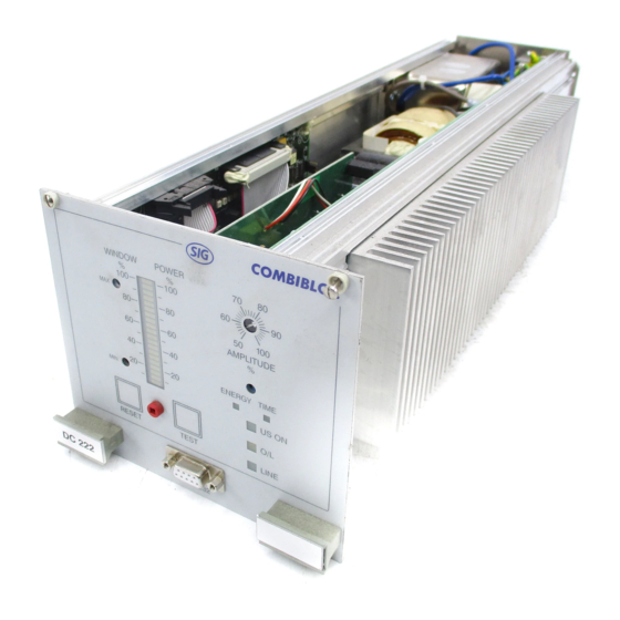
Description of the Unit Controls 4.6.1 Front Panel of the DC Power Supply Module Fig. 4-4 Controls on the front panel of the DC 315/480 power supply module Maximum power window (green) Power bar graph (red) Amplitude setting Tuning potentiometer... - Page 37 Description of the Unit Fig. 4-5 Controls on the front panel of the DC 222 power supply module Maximum power window (green) Power bar graph (red) Amplitude setting Tuning Energy welding Potentiometer Weld time or Max/min power energy setting Time welding Connector for power Ultrasonics on...
- Page 38 Description of the Unit The front panel of the DC power supply module provides the following controls and indicators: Tab. 4-4 Controls and indicators on the front panel of the DC power supply module Control Function US ON Indicates that ultrasonics output is activa- (Ultrasonics on) ted.
- Page 39 Description of the Unit 4.6.2 Rear of the DC Power Supply Fig. 4-6 Rear of the DC power supply Mains supply connector Type plate RF connector Model UPS 480 800 W Power Input 200-245 V, 5 A, 50/60 Hz Serial No. Year of Manufacture Control/alarm connector...
-
Page 40: Setting The Mode Of Operation
Description of the Unit Setting the Mode of Operation On delivery, Time mode is set as mode of operation. Fig. 4-7 Jumper for setting the mode of operation 1 2 3 4 5 6 7 8 1 2 3 4 5 6 7 8 Tab. - Page 41 Description of the Unit To setting a mode, press the Reset button. After approx. 3 seconds, the power bar LED will display the value adjusted. You can change this value using the potentiometer. On the power bar LED 1 red bar corresponds to 50ms (in case of time control) 1 red bar corresponds to 50 Joule (in case of energy control).
- Page 42 Description of the Unit 4-14 Digital Compact...
-
Page 43: Startup
Packing for Return If possible, please use the original packing and packing material. In case of questions concerning packing and transport safety, please contact BRANSON Ultrasonics. Storage If no special agreements have been made concerning packing and storage, the unit must be transported and stored with or without packing under “normal“... -
Page 44: Installation
Startup Installation When installing or removing modules and when modifying the system, the relevant precautions against electrostatics have to be taken in order to prevent damage to internal components of the system. Before installing or removing a module, always touch a grounded part of the system in order to eliminate a given difference in potential bet- ween your body and the system. - Page 45 Startup 5.2.2 Installing the Acoustic Stack The acoustic stack consisting of converter, booster and horn must be assembled properly prior to installation in the press unit. NOTE! Booster and horn are not included in the scope of delivery. The acoustic stack is an acoustic precision tool which must be treated with greatest care.
- Page 46 4. Screw converter to booster and then converter/booster to the horn applying a torque of 13 Nm. Use one or two BRANSON open end wrenches (011-803-001). Fig. 5-1 Installing the horn Tab.
- Page 47 NEVER attempt to assemble or disassemble the acoustic stack by holding the booster or converter in a vice (see Fig. 5-2). In case you have to assemble or disassemble acoustic stacks regularly, a special installation fixture is available from BRANSON Ultrasonics. Fig. 5-2 Securing the acoustic stack...
-
Page 48: Ultrasonics Test
3. Make sure that all components are tightened with the correct tor- que. 4. In case the above measures do not solve the problem, please con- tact your BRANSON representative or the BRANSON service: (++49) (0) 06074-497 784 Digital Compact... -
Page 49: Electrical Connections
Electrical Connections Electrical Connections Fig. 6-1 Electrical connectors at the rear of the power supply Model UPS 480 Power 800 W 200-245 V, 5 A, 50/60 Hz Input Serial No. Year of Manufacture Tab. 6-1 Connectors at the rear of the DC power supply module Connector Function J1 Mains supply... -
Page 50: Pc Connector (J4, Front)
Electrical Connections PC Connector (J4, Front) Using a serial cable, you can connect a PC to the JF connector (9-pin SUB-D socket). If you install the required software available at BRAN- SON Ultrasonics, you can • save the data of each weld cycle to a file, •... -
Page 51: Control/ Alarm Connector (J3)
Electrical Connections Control/ Alarm Connector (J3) Tab. 6-3 Pin assignment of the J3 connector (15 pins) Pin Assignment I/O Type Description Window high > digital active low: when exceeding the maximum power during the weld, the Window high signal is output. O/L inverted >... - Page 52 Electrical Connections Tab. 6-3 Pin assignment of the J3 connector (15 pins) Pin Assignment I/O Type Description Reset Ext. < digital 24V PLC input signal At 24V, the system is reset Seek – digital Ampl. In < analog Amplitude control 0...100% (no ope- ration below 20%) Range: –10V...+10V (0V= 50%) To reset a Window low or Window high signal, release a new start...
- Page 53 Electrical Connections 6.2.1 Notes on Overload Alarm The power supply module Digital Compact is protected against over- voltage, overcurrent and excessive phase displacement. These conditi- ons possibly have the following reasons: • Real overload conditions, due to an amplitude too high, a force too high being exerted onto the workpieces or exceeding the maximum power of the module.
- Page 54 Electrical Connections 6.2.3 Amplitude Control Depending on the internal DIP switch settings (please refer to chapter 6.2.6), you can reduce the amplitude by up to 50 % with respect to the maximum amplitude as follows: • Using an external control. This control action is a continuous adjustment during the welding process.
- Page 55 Electrical Connections 6.2.5 Autotune The Autotune function is used to determine the exact horn frequency automatically. The Autotune function consists of two individual functions: • Auto-Seek An ultrasonic test signal is applied to the acoustic stack once per minute. This way, the current resonant frequency of the horn is determined regularly which may change due to heat expansion.
- Page 56 Electrical Connections 6.2.6 Select Switches for Additional Functions The following functions can be set using the DIP switches or the soft- ware: • Seek Options for control, monitoring and storage of the operating frequency. • Amplitude control Enables changing the amplitude (50% to 100%) via external control or maintaining a fixed value respectively.
- Page 57 Electrical Connections Tab. 6-4 DIP switch settings for additional functions (default settings are bold.) Function Options Switch Position Seek on power up: Checks the horn frequency 1 - ON upon power-up and stores it 1 - OFF in memory Autoseek: Checks the horn frequency 2 - ON once per minute, timed from...
- Page 58 Electrical Connections Tab. 6-4 DIP switch settings for additional functions (default settings are bold.) Fre- Reset frequency memory 5 - ON quency The frequency is reset by 5 - OFF memory the external reset signal. External: (50 % to 100%) controlled by customer.
-
Page 59: Troubleshooting
Power supply units of the DC series must not be serviced by other than qualified technicians using test and repair equipment as well as repair procedures and spare parts approved by BRANSON Ultrasonics. In case of unauthorised attempts to repair or modify the modules the warranty will terminate. -
Page 60: Error Elimination Tables
• Replace the power supply module. If during weld cycle. this solves the problem, install another module and send the defective one to BRANSON Ultrasonics. • Replace the fuse (please refer to Fig. Line fuse responds. 7-1). Digital Compact... - Page 61 Troubleshooting Fig. 7-1 Position of internal fuse Tab. 7-2 Fuses 20 kHz 30 kHz 40 kHz 15 AT (5 x 20 mm) 8 AT (5 x 20 mm) 6 AT (5 x 20 mm) Digital Compact...
- Page 62 No overload alarm. • Replace power supply module. If this solves the problem, install another module and send the defective one to BRANSON Ultrasonics. Ultrasonic power app- lied to the horn is not • No supply with ultrasonic energy. displayed on the bar- Replace power supply module.
- Page 63 TEST key necessary. or during weld cycle. • Check the converter and replace if necessary. • Replace the power supply module. In case of malfunction, install another module and send the defective one to BRANSON Ultrasonics. Digital Compact...
- Page 64 If none of the reme- In this case, replace the power supply dial actions described module and send the defective one to is successful, imme- BRANSON Ultrasonics. diately de-energise the equipment! The temperature of • Check for fretting corrosion on the horn, booster and mating surfaces of the acoustic stack.
- Page 65 Take greatest care when conditioning. In case of improper condi- tioning the components can be damaged. If in doubt, send the components to BRANSON Ultrasonics. 1. Disassemble the acoustic stack and clean the mating surfaces using a dry cloth or paper towel.
- Page 66 If the deposit is then not removed, send the horn, or booster respectively, to BRANSON Ultrasonics. 10.Please observe the following information before you use the horn stud or a horn of aluminium again: Clean the knurled end of the horn stud using a wire brush or a cardboard edge to remove aluminium residue.
-
Page 67: Maintenance
Maintenance Maintenance DANGER! STOP Prior to cleaning and maintenance work, the welding system must be depressurised and disconnected from the mains. De-energise the equipment and disconnect from mains supply. Please observe the following hints to ensure long and trouble-free ope- ration : Cleaning the Housing •... -
Page 68: Cleaning Internal Parts Of The Power Supply
Maintenance Cleaning internal Parts of the Power Supply In case the systems are force-ventilated check ventilators for contami- nation at regular intervals. Depending on the degree of contamination clean the inner parts of the power supply at regular intervals using compressed air. If the module is operated in a dusty environment cleaning might be required weekly. -
Page 69: Glossary Of Terms
Ultrasonic power supplies with Advanced module offer the possibility to change the horn amplitude within a weld. This is achieved via an exter- nal control or using a BRANSON Controller. Amplitude profiling allows for precise control of the energy applied to a part during welding, thus controlling the heating of the mating surface. - Page 70 Glossary of Terms Distance welding In this mode of operation a predefined distance (vertical feeding motion of the horn onto or into the workpiece) is effected and during that time ultrasonics is output. Down Speed The velocity at which the acoustic stack descends to the part. Dynamic Trigger See Trigger.
- Page 71 Glossary of Terms Near field welding Welding at a distance shorter than 0.25 inch (6mm) from the point of horn contact with the workpiece. Compare far field welding. Overload If the ultrasonic power applied exceeds the allowed maximum power of the power supply, the power supply switches to overload condition and stops output of ultrasonics.
- Page 72 Glossary of Terms Weld force profiling The weld quality can be improved by changing the weld force (genera- ted pneumatically). Usually, the weld cycle starts with a high level of force. After a pre-defined period of time, a fast proportional valve swit- ches to lower force: The energy transferred to the joint is decreased, causing the plastics in the joint area to melt more slowly.
-
Page 73: Product Observation
• Repeated errors and malfunctions. • Difficulties experienced with this manual BRANSON Ultrasonics A Subsidiary of EMERSON TECHNOLOGIES GmbH & Co. Waldstraße 53 - 55 D-63128 Dietzenbach Telephone (0 60 74) 497 784 Telefax (0 60 74) 497 789 Internet: www.branson.de... - Page 74 Product Observation 10-2 Digital Compact...
-
Page 75: Index
Index acoustic stack 5-5 Acoustic Stack, installation of 5-3 amplitude 9-1 amplitude Control 6-6 amplitude control 6-5 amplitude regulation, jumper 4-2 Auto-Seek 6-7 Autotune 6-7 Autotune/Memory 6-7 booster 3-4 cleaning 8-1 converter 3-4 Designated Use 2-6 dimensions 4-5 DIP switches 6-8 dissasembly of acoustic stack 5-5 Drehmomente 5-3 electromagnetic compatibility 2-12... - Page 76 mating surfaces 5-3 O/L signal 6-4 open end wrench 5-4 operator personnel 1-6 overload alarm 6-5 packaging 5-1 packing for return 5-1 PC connector 6-2 pin assignment, J3 6-3 pin assignment, J4 6-2 PLC 6-3 ramp start 6-6 reset 6-4 resonant frequency 6-7 service personnel 1-6 settling time 6-6...
Need help?
Do you have a question about the DC 315 and is the answer not in the manual?
Questions and answers