Sign In
Upload
Manuals
Brands
Branson Manuals
Power Supply
DCX A Series
Branson DCX A Series Manuals
Manuals and User Guides for Branson DCX A Series. We have
1
Branson DCX A Series manual available for free PDF download: Original Instructions Manual
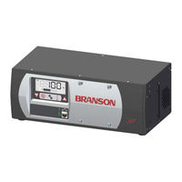
Branson DCX A Series Original Instructions Manual (188 pages)
Brand:
Branson
| Category:
Power Supply
| Size: 13.61 MB
Table of Contents
Table of Contents
5
Chapter 1:Safety And Support
13
Safety Requirements and Warnings
14
Figure 1.1 Safety-Related Labels Found on the DCX a Power Supply
15
General Precautions
16
Warranty Statement, Disclaimer
18
Table 1.1 Warranty Period
18
How to Contact Branson
20
Returning Equipment for Repair
21
Table 1.2 Branson Contacts
23
Obtaining Replacement Parts
24
Chapter 2:Introduction
25
Models Covered
26
Table 2.1 Models Covered in this Manual
26
Figure 2.1 the DCX a Power Supply (Horizontal)
27
Figure 2.2 the DCX a Power Supply (Vertical)
27
Compatibility with Other Branson Products
28
Table 2.2 Power Supply Compatibility with Branson Converters
28
Features
29
Controls and Indicators
32
Figure 2.3 DCX a Power Supply Front Panel Controls and Indicators
32
Table 2.3 DCX a Power Supply Front Panel Controls and Indicators
32
Table 2.4 LCD Description
32
Figure 2.4 LCD Description
34
Figure 2.5 DCX a Power Supply Back Panel (Horizontal)
37
Figure 2.6 DCX a Power Supply Bottom Panel (Vertical)
37
Table 2.5 Connections to the DCX a Power Supply
37
Welding Systems
38
Glossary of Terms
39
Chapter 3:Delivery And Handling
41
Shipping and Handling
42
Table 3.1 Shipping Specifications
42
Receiving
43
Table 3.2 Inspect the Power Supply
43
Unpacking the Power Supply
44
Table 3.3 Unpacking the Power Supply
44
Take Inventory of Small Parts
45
Table 3.4 Small Parts Included: Power Supply Assemblies
45
Table 3.5 DCX a Power Supply System Cables
45
Returning Equipment
46
Chapter 4 4:Technical Specifications
48
Table 4.1 Environmental Specifications
48
Table 4.2 Electrical Input Operating Voltages
48
Table 4.3 Input Current and Circuit Breaker Specifications
49
Table 4.4 Continuous Duty Maximum Power
49
Physical Description
50
Table 4.5 Dimension and Weight of DCX a Power Supply
50
Declaration of Conformity
51
Figure 4.1 Declaration of Conformity
51
Chapter 5:Installation And Setup
53
About Installation
54
Installation Requirements
55
Figure 5.1 DCX a Power Supply Benchtop Dimensional Drawing
55
Figure 5.2 DCX a Power Supply Vertical Mount Dimensional Drawing (400 W, 750 W and 800 W)
55
Table 5.1 DCX a Power Supply Benchtop Dimensional Drawing
56
Figure 5.3 DCX a Power Supply Vertical Mount Dimensional Drawing (1.25 Kw and 1.5 Kw)
58
Table 5.3 DCX a Power Supply Vertical Mount Dimensional Drawing (1.25 Kw and 1.5 Kw)
58
Figure 5.4 DCX a Power Supply Vertical Mount Dimensional Drawing (2.5 Kw and 4 Kw)
59
Table 5.4 DCX a Power Supply Vertical Mount Dimensional Drawing (2.5 Kw and 4 Kw)
59
Table 5.5 Environmental Requirements
60
Table 5.6 Input Current and Circuit Breaker Specifications
60
Installation Steps
61
Figure 5.5 LCD Viewing Angle
63
Figure 5.6 DCX a Power Supply Connections (Horizontal Model)
64
Table 5.7 DCX a Power Supply Connections (Horizontal Model)
64
Figure 5.7 DCX a Power Supply Connections (Vertical Model)
65
Table 5.8 DCX a Power Supply Connections (Vertical Model)
65
Figure 5.8 User I/O Cable Identification and Wire Color Diagram
67
Table 5.9 User I/O Cable Identification and Wire Color Diagram
67
Table 5.10 User I/O Cable Pin Assignments
68
Table 5.11 Digital Input Functions
70
Table 5.12 Digital Output Functions
72
Table 5.13 Analog Input Functions
74
Table 5.14 Analog Output Functions
75
Table 5.15 Default Branson User I/O Connector PIN Assignments, V6.0
76
Table 5.16 Default Branson User I/O Connector PIN Assignments, V6.5
78
Figure 5.9 Typical Digital I/O Wiring Examples
80
Figure 5.10 Typical Analog I/O Wiring Examples
80
Figure 5.11 RF Cable Connection
81
Table 5.17 RF Cable Connection
81
Table 5.18 Input Power Connection
82
Power Supply Setup
84
Assembling the Acoustic Stack
85
Figure 5.12 Assembling the Acoustic Stack
86
Table 5.19 Acoustic Stack Description
86
Table 5.20 Stack Torque Values
87
Table 5.21 Tools
87
Table 5.22 20 Khz System
88
Table 5.23 30 Khz System
88
Table 5.24 40 Khz System
88
Figure 5.13 Connecting Tip to Horn
89
Table 5.25 Tip to Horn Torque Values
89
Converter Cooling
90
Table 5.26 Continuous Duty Max. Power & Full Power Duty Cycle
90
Table 5.27 Converter Cooling Procedure
91
Testing the Installation
92
Still Need Help
93
Chapter 6 6:Converters and Boosters
96
Figure 6.1 20 Khz CH-20S Converter Dimensions
96
Table 6.1 20 Khz CH-20S Converter Dimensions
96
Figure 6.2 20 Khz Booster Dimensions
97
Table 6.2 20 Khz Booster Dimensions
97
Figure 6.3 20 Khz Converter/Booster/Horn, Typical Dimensions
98
Table 6.3 20 Khz Converter/Booster/Horn, Typical Dimensions
98
Figure 6.4 30 Khz Converter Dimensions
99
Table 6.4 30 Khz Converter Dimensions
99
Figure 6.5 30 Khz Booster Dimensions
100
Table 6.5 30 Khz Booster Dimensions
100
Figure 6.6 30 Khz Converter/Booster/Horn, Typical Dimensions
101
Table 6.6 30 Khz Converter/Booster/Horn, Typical Dimensions
101
Figure 6.7 40 Khz, 4TR Converter Dimensions
102
Table 6.7 40 Khz, 4TR Converter Dimensions
102
Figure 6.8 40 Khz Booster Dimensions
103
Table 6.8 40 Khz Booster Dimensions
103
Figure 6.9 40 Khz Converter/Booster/Horn, Typical Dimensions
104
Table 6.9 40 Khz Converter/Booster/Horn, Typical Dimensions
104
Chapter 7:Operation
107
Setting Primary Parameters
108
Table 7.1 Summary of Weld Modes
108
Table 7.2 Continuous Mode Operational Sequence
109
Table 7.3 Time Mode Parameters
111
Table 7.4 Selecting Time Mode
111
Table 7.5 Setting Time Mode Parameters
112
Table 7.6 Energy Mode Parameters
113
Table 7.7 Selecting Energy Mode
113
Table 7.8 Setting Energy Mode Parameters
114
Table 7.9 Peak Power Mode Parameters
115
Table 7.10 Selecting Peak Power Mode
115
Table 7.11 Setting Peak Power Mode Parameters
116
Table 7.12 Ground Detect Mode Parameters
117
Table 7.13 Selecting Ground Detect Mode
117
Table 7.14 Setting Ground Detect Mode Parameters
118
Setting the Amplitude
119
Figure 7.1 LCD at Power up
119
Table 7.15 Setting the Amplitude Using the Front Panel Controls
119
Figure 7.2 LCD When in External Amplitude Control Mode
120
Resetting the Power Supply Alarms
121
Table 7.16 Resetting the DCX a Power Supply
121
Configuring the Power Supply Registers
122
Table 7.17 Steps to Configure the Power Supply Registers
122
Table 7.18 Power Supply Registers
124
LCD Bar-Graph
127
Table 7.19 Power Bar-Graph Interpretation Examples
127
Table 7.20 Frequency Bar-Graph Interpretation - 20 Khz (50 Hz Segment)
128
Table 7.21 Frequency Bar-Graph Interpretation - 30 Khz (76 Hz Segment)
128
Table 7.22 Frequency Bar-Graph Interpretation - 40 Khz (100 Hz/Segment)
129
Table 7.23 Frequency Bar-Graph Interpretation Examples
129
Ultrasonics Test Procedure
130
Table 7.24 Power Supply Ultrasonic Test Procedure (Front Panel)
130
Using the I/O Connections
132
Figure 7.3 Test Connections
132
Table 7.25 Power Supply Ultrasonic Test Procedure (User I/O)
132
Chapter 8:Maintenance
133
General Maintenance Considerations
134
DCX a Power Supply Preventive Maintenance
136
Table 8.1 Stack Reconditioning Procedure
138
Figure 8.1 Reconditioning Stack Mating Surfaces
139
Table 8.2 Reconditioning Stack Mating Surfaces
139
Table 8.3 Stack Torque Values
139
Table 8.4 Stack Reassembly for a 20 Khz System
140
Table 8.5 Stack Reassembly for a 30 Khz System
140
Table 8.6 Stack Reassembly for a 40 Khz System
141
Table 8.7 Stud Torque Values
141
Recommended Spare Stock
142
Table 8.8 DCX a Power Supply System Cables
142
Table 8.9 Suggested Spares
143
Table 8.10 Converters Compatible with the DCX a Power Supply
144
Table 8.11 DCX a Power Supply Compatible Boosters
145
Table 8.12 Other Items Used with the DCX a Power Supply
147
Circuit Diagram
148
Figure 8.2 Interconnect Diagram
148
Troubleshooting
149
Table 8.13 Troubleshooting
149
Table 8.14 Troubleshooting Common Electrical Problems
150
Table 8.15 Troubleshooting Ultrasonic Power Problems
151
Table 8.16 Troubleshooting Weld Cycle Problems
152
Cold Start Procedure
153
Table 8.17 Steps to Perform a Cold Start
153
Appendix A:alarms
155
Overload Alarms (Group 0)
156
Table A.1 Overload Alarms (Group 0)
156
Cutoff Alarms (Group 1)
158
Table A.2 Cutoff Alarms (Group 1)
158
Setup Alarms (Group 2)
159
Table A.3 Cycle Modified Alarms (Group 2)
159
Cycle Modified Alarms (Group 3)
160
Table A.4 Cycle Modified Alarms (Group 3)
160
Warning Alarms (Group 4)
161
Table A.5 Warning Alarms (Group 4)
161
Limit Alarms (Group 5)
162
Table A.6 Limit Alarms (Group 5)
162
Equipment Failure Alarms (Group 6)
163
Table A.7 Equipment Failure Alarms (Group 6)
163
No Cycle Alarms (Group 7)
165
Table A.8 no Cycle Alarms (Group 7)
165
Communication Failure Alarms (Group 8)
166
Table A.9 Communication Failure Alarms (Group 8)
166
Hardware Alarms (Group A)
167
Table A.10 Hardware Alarms (Group A)
167
Non-Cycle Overload Alarms (Group B)
168
Table A.11 Non-Cycle Overload Alarms (Group B)
168
Appendix B:timing Diagrams
171
Figure B.1 RF Switching Direct with Feedback with and Without Alarm
172
Figure B.2 RF Switching I/O Direct with Feedback with and Without Alarm
172
B.1 Timing Diagrams
172
Figure B.3 RF Switching I/O Direct with Feedback with and Without Alarm and Load on Start
173
Figure B.4 RF Switching I/O with off with and Without Alarm and Load on Start
173
Figure B.5 RF Switching I/O with off with Feedback with and Without Alarm
174
Figure B.6 RF Switching with off with Feedback with and Without Alarm
174
Figure B.7 Timing Diagram for All Other Modes with Actuator
175
Figure B.8 Timing Diagram for Cycle Abort with Actuator
176
Figure B.9 Timing Diagram for Ground Detect with Actuator
177
Appendix C:signal Diagrams
180
Figure C.1 Continuous Mode
180
C.1 Signal Diagrams
180
Figure C.2 Time Mode
181
Figure C.3 AE Actuator
182
C:signal Diagrams
180
Advertisement
Advertisement
Related Products
Branson DC 315
Branson DC 480
Branson DC 222
Branson DHA-1000
Branson 2000Xc
Branson 900M Series
Branson 905M 117V
Branson 920M
Branson 930M
Branson EMERSON 2000 X energy
Branson Categories
Tractor
Power Supply
Ultrasonic Jewelry Cleaner
Controller
Laboratory Equipment
More Branson Manuals
Login
Sign In
OR
Sign in with Facebook
Sign in with Google
Upload manual
Upload from disk
Upload from URL