Table of Contents
Troubleshooting

Subscribe to Our Youtube Channel
Related Manuals for Branson Emerson DCX V Series


Summary of Contents for Branson Emerson DCX V Series
- Page 1 Original Instructions 4000851 - REV. 02 DCX V Series Power Supply O p e r a t i n g M a n u a l Branson Ultrasonics Corp. 120 Park Ridge Road Brookfield, CT 06804 (203) 796-0400 http://www.bransonultrasonics.com...
- Page 2 Copyright and Trademark Notice Copyright © 2023 Branson Ultrasonics Corporation. All rights reserved. Contents of this publication may not be reproduced in any form without the written permission of Branson Ultrasonics Corporation.
- Page 3 Foreword Congratulations on your choice of a Branson Ultrasonics Corporation system! The Branson DCX V Series System is process equipment for the joining of plastic parts using ultrasonic energy. It is the newest generation of product using this sophisticated technology for a variety of customer applications. This Operating Manual is part of the documentation set for this system, and should be kept with the equipment.
- Page 4 4000851 REV. 02...
-
Page 5: Table Of Contents
Compatibility with other Branson Products ........16... - Page 6 Troubleshooting ........... . 105 Cold Start Procedure.
- Page 7 List Of Figures Chapter 1: Safety and Support Figure 1.1 Safety-related Labels found on the DCX V Series Power Supply (Horizontal)..4 Figure 1.2 Safety-related Labels found on the DCX V Series Power Supply (Vertical) ..4 Chapter 2: Introduction to the DCX V Power Supply Figure 2.1 The DCX V Power Supply (Horizontal) .
- Page 8 Appendix B: Sequence Diagrams Figure B.1 Weld Cycle........... 112 Figure B.2 Weld Cycle.
- Page 9 Table 2.2 Power Supply Compatibility with Branson .......16 Table 2.3 DCX V Series Front Panel Indicators .
- Page 10 Table 5.6 20 kHz Converter ..........67 Table 5.7 20 kHz Booster.
-
Page 11: Chapter 1: Safety And Support
How to Contact Branson ........ -
Page 12: Safety Requirements And Warnings
This chapter contains an explanation of the different Safety Notice symbols and icons found both in this manual and on the product itself and provides additional safety information for ultrasonic welding. This chapter also describes how to contact Branson for assistance. - Page 13 CAUTION Loud Noise Hazard Loud noise hazard. Ear protection must be worn. CAUTION Heavy Object Heavy object. To avoid muscle strain or back injury, use lifting aids and proper lifting techniques. NOTICE Indicates a possible damaging situation If this situation is not avoided, the system or something in its vicinity might get damaged.
-
Page 14: Figure 1.1 Safety-Related Labels Found On The Dcx V Series Power Supply (Horizontal)
1.1.2 Symbols Found on the Product The DCX V Series Power Supply has several safety-related labels on it to indicate the presence of hazardous voltages inside the unit Figure 1.1 Safety-related Labels found on the DCX V Series Power Supply (Horizontal) Figure 1.2 Safety-related Labels found on the DCX V Series Power Supply (Vertical) 4000851 REV. -
Page 15: General Precautions
General Precautions Take the following precautions before servicing the power supply: • Be sure the power switch is in the off position before making any electrical connections • To prevent the possibility of an electrical shock, always plug the power supply into a grounded power source •... - Page 16 WARNING Corrosive Material Hazard Processing of many materials, such as PVC, can be hazardous to an operator’s health and could cause corrosion/damage to the equipment. Use proper ventilation and take protective measures. 1.2.3 Setting up the Workplace Measures for setting up a workplace for safe operation of the ultrasonic welder are outlined in Chapter 4: Installation and Setup.
-
Page 17: How To Contact Branson
How to Contact Branson Branson is here to help you. We appreciate your business and are interested in helping you successfully use our products. To contact Branson for help, use the following telephone numbers, or contact the office nearest you. - Page 18 Japan Headquarters Kanagawa 243-0021 Fax: 81-46-288-8892 Division of Emerson Japan Japan Ltd. #803, 8F Dongil Techno Town Branson Korea Co., Ltd. 823, Kwan Yang-2dong, Tel: 82-1577-0631 Dong An-gu Korea Fax: 82-31-422-9572 An Yang-si, Kyung Ki-do, 431-062 Korea No. 20, Jalan Rajawali 3,...
-
Page 19: Table 1.4 Authorized Service Centers (Europe)
Tel: 49 (0)6074/497-784 European Headquarters Waldstraße 53-55 Fax: 49 (0)6074/497-199 Germany 63128 Dietzenbach, info@branson.de Germany Via Dei Lavoratori, 25 Branson Ultrasuoni, S.r.l. Tel: 39-02-660-8171 20092 Cinisello Balsamo Italy Fax: 39-02-660-10480 Milano, Italy Branson Ultrasonics B.V. P.O. Box 9, 3760 Soest Tel: 31-35-60-98101... - Page 20 Table 1.4 Authorized Service Centers (Europe) Name Address Tel/Fax Number Edificio Emerson C/Can Pi, 15 1ª Planta (Antigua Carretera del Prat) Branson Ultrasonidos S.A.E. Tel: 34-93-586-0500 Polígono Industrial Gran Vía Spain Fax: 34-93-588-2258 08908 HOSPITALET DE LLOBREGAT (BARCELONA) Spain Sonifers: Case Postale 1031...
- Page 21 Models Covered ..........12 Relation to other Branson Models ....... 15 Compatibility with other Branson Products .
-
Page 22: Models Covered
Models Covered This manual covers all models of the DCX V Series Power Supply. Table 2.1 Models Covered in this Manual Frequency Power Model Horizontal 101-132-1808 1250 W Vertical 101-132-1815 Horizontal 101-132-1809 20 kHz 2500 W Vertical 101-132-1816 Horizontal 101-132-1810 4000 W Vertical 101-132-1817... -
Page 23: Figure 2.2 The Dcx V Power Supply (Vertical)
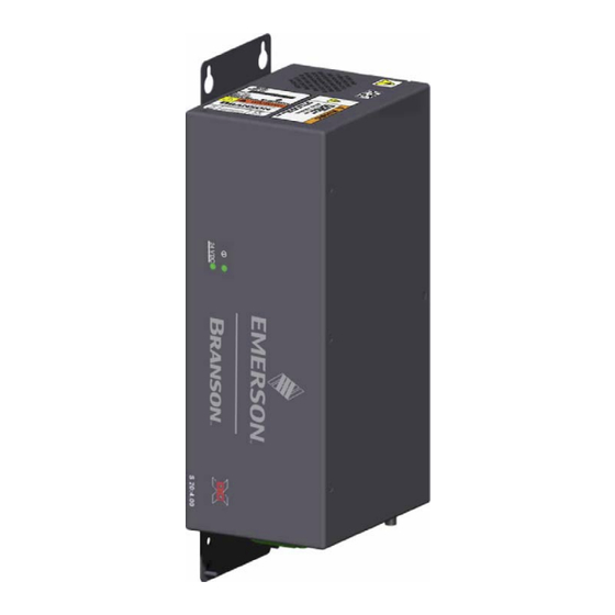
Figure 2.2 The DCX V Power Supply (Vertical) The DCX V Power Supply generates ultrasonic energy through an ultrasonic converter for welding plastics. Several models are available, depending on the desired frequency (for example, 20 kHz), the desired power range (for example, 2.5 kW), and the intended mounting arrangement (horizontal or vertical). - Page 24 2.1.2 Power Supply Manual Set The following documentation is available in electronic format for the Branson DCX V Power Supply: • DCX V Series Power Supply Instruction Manual (4000851) • DCX V Series Power Supply Quick Start Guide (4000842) •...
-
Page 25: Relation To Other Branson Models
Relation to other Branson Models The DCX V Series replaces the 2000b/bdc, 2000P, PGA, and NP power supplies. NOTICE The DCX V is not a direct replacement of the above mentioned power supplies. Please Contact Branson Product Support for additional information. 4000851 REV. 02... -
Page 26: Compatibility With Other Branson Products
Compatibility with other Branson Products Table 2.2 Power Supply Compatibility with Branson DCX V Model Converter CR-20 20 kHz / 1250 W CR-20S CR-20C 20 kHz / 2500 W CH-20S (932 AH SPL) CH-20C 20 kHz / 4000 W CS-20S... -
Page 27: Features
You should only use this feature when advised to do so by Branson • Horn Signature: Using the DCX Web Page Interface, you may scan your ultrasonic stack to view its operating frequency on your computer, using digital readouts and bar graphs to give you the best picture of the stack’s operation... - Page 28 2.4.4 Converter/Booster/Horn Assembly The Converter The ultrasonic electrical energy from the power supply is applied to the converter (sometimes called the transducer). This transforms the high frequency electrical oscillations into mechanical vibrations at the same frequency as the electrical oscillations. The heart of the converter is piezoelectric ceramic elements.
-
Page 29: Controls And Indicators
Controls and Indicators 2.5.1 DCX V Series Front Panel Indicators Figure 2.3 DCX V Series Front Panel Indicators Table 2.3 DCX V Series Front Panel Indicators Item Name Function Power-On Lights when the power supply is connected to main power indicator and the power switch is on. -
Page 30: Figure 2.5 Dcx V Series Bottom Panel (Vertical)
Figure 2.5 DCX V Series Bottom Panel (Vertical) Table 2.4 Connections to the DCX V Series Power Supply Item Name Function Circuit Breaker / Power Turns the AC main power on or off. Switch Detachable connector block for connecting the input Line Input Connector power. -
Page 31: Welding Systems
Welding Systems 2.6.1 Principle of Operation Thermoplastic parts are welded ultrasonically by applying high frequency vibrations to the parts being assembled. The vibrations, through surface and intermolecular friction, produce a sharp rise in temperature at the welding interface. When the temperature is high enough to melt the plastic, there is a flow of material between the parts. -
Page 32: Glossary
Glossary The following terminology may be encountered when using or operating a DCX V Series ultrasonic welding system: Actuator: The unit which houses the converter/booster/horn stack assembly in a rigid mounting, allowing the stack to move up and down, either mechanically or pneumatically, applying force to the part at a user-adjustable force and velocity. - Page 33 Joint: The weld surfaces. Parameter: A unique factor or element which affects the welding operation in a particular mode. Parameter Range: Valid range of parameters accepted for a particular setup. Power Supply: The electronic instrument in an ultrasonic assembly system which changes conventional 50/60 Hz electrical power into high frequency electrical power at 20 kHz, 30 kHz or 40 kHz.
- Page 34 4000851 REV. 02...
-
Page 35: Chapter 3: Delivery And Handling
Chapter 3: Delivery and Handling Shipping and Handling ........26 Receiving . -
Page 36: Shipping And Handling
Shipping and Handling CAUTION Heavy Object The power supply may be heavy. Handling, unpacking, and installation may require the assistance of a colleague or the use of lifting platforms or hoists. 3.1.1 Environmental Specifications The DCX V Series Power Supply is an electronic unit that converts line voltage to ultrasonic energy and responds to user input for regulating the weld process. -
Page 37: Receiving
Scope of Delivery Branson equipment is carefully checked and packed before dispatch. It is recommended, however, that you follow the procedure below upon receiving your DCX V Series Power Supply. -
Page 38: Unpacking The Power Supply
Unpacking the Power Supply NOTICE If there are any visible signs of damage to the shipping containers or the product, or you later discover hidden damage, NOTIFY YOUR CARRIER IMMEDIATELY. Save the packing material. The power supply is fully assembled. It is shipped in a sturdy cardboard box. Some additional items are shipped in the box with the power supply. -
Page 39: Take Inventory Of Small Parts
Take Inventory of Small Parts Table 3.4 Small Parts included (=x): Power Supply Assemblies Part or Kit 20 kHz 30 kHz 40 kHz Mylar® plastic film Washer Kit Silicone Grease Spanners (2) a. Mylar is a registered trademark of DuPont Teijin Films. 3.4.1 Cables The RF cable connects the power supply to the converter. -
Page 40: Returning Equipment
Returning Equipment If you are returning equipment to Branson Ultrasonic Corporation, please call your Customer Service Representative to receive approval to return the goods. Refer to How to Contact Branson. 4000851 REV. 02... -
Page 41: Chapter 4: Installation And Setup
Chapter 4: Installation and Setup About Installation ......... . . 32 Installation Requirements. -
Page 42: About Installation
About Installation This chapter is intended to help the installer with the basic installation and setup of your new DCX V Series Power Supply. CAUTION Heavy Object The power supply, and related components are heavy. Handling, unpacking, and installation may require the assistance of a colleague or the use of lifting platforms or hoists. -
Page 43: Installation Requirements
Installation Requirements This section covers the location requirements, mounting options, power supply dimensions, environmental requirements, and electrical requirements, to help you plan and execute your installation successfully. 4.2.1 Location The DCX V Power Supply comes in two different models Horizontal (benchtop) and Vertical (which may be back mounted or side mounted). - Page 44 Figure 4.1 DCX V Power Supply Benchtop Dimensional Drawing 4000851 REV. 02...
- Page 45 Figure 4.2 DCX V Power Supply Vertical Mount Dimensional Drawing (400 W, 750 W and 800 W) 5.22 in (132.6 mm) 4.5 in 7.49 in (114 mm) (190.2 mm) 3.5 in (89 mm) 3.0 in (76 mm) recommended fan clearance 15.75 in 17.38 in (400 mm)
-
Page 46: Figure 4.3 Dcx V Power Supply Vertical Mount Dimensional Drawing (1.25 Kw And 1.5 Kw)
Figure 4.3 DCX V Power Supply Vertical Mount Dimensional Drawing (1.25 kW and 1.5 kW) 4000851 REV. 02... -
Page 47: Figure 4.4 Dcx V Power Supply Vertical Mount Dimensional Drawing (2.5 Kw And 4 Kw)
Figure 4.4 DCX V Power Supply Vertical Mount Dimensional Drawing (2.5 kW and 4 kW) 4000851 REV. 02... -
Page 48: Table 4.1 Environmental Requirements
4.2.2 Environmental Requirements Verify the DCX V Power Supply is operated in an environment that meets the temperature and humidity requirements indicated in Table 4.1. Table 4.1 Environmental Requirements Environmental Condition Acceptable Range Ambient Operating Temperature +41º F to +104º F (+5º C to +40º C) Humidity 30% to 95% (non-condensing) Operating Altitude... -
Page 49: Installation Steps
Performance and results can suffer if the RF cable is crushed, pinched, damaged or modified. Contact your Branson Representative if you have special cable requirements. Do not place the power supply on the floor or in other locations that will allow dust, dirt or contaminants to be drawn into the power supply. - Page 50 NOTICE Do not block exhaust and intake air circulation, which is needed to maintain a safe operating temperature. 4.3.1.1 Horizontal (Benchtop) Mounting The Horizontal DCX V Power Supply is designed to be placed on a workbench (rubber feet on bottom) within cable-length limits of the stack. It has one fan which draws cooling air from the left side to the right side, which must be free from obstruction.
-
Page 51: Figure 4.5 Dcx V Power Supply Connections (Horizontal Model)
4.3.2 Electrical Connections Figure 4.5 DCX V Power Supply Connections (Horizontal Model) Table 4.3 DCX V Series Power Supply Connections (Horizontal Mode) Item Description RF Cable (Ferrite End) Ground Screw RF Connector Input Power Connector Circuit Breaker (On/Off Switch) 24 V 24 VR User I/O Connectors Ethernet Port... -
Page 52: Figure 4.6 Dcx V Power Supply Connections (Vertical Model)
Figure 4.6 DCX V Power Supply Connections (Vertical Model) Table 4.4 DCX V Series Power Supply Connections (Horizontal Mode) Item Description Ground Screw Input Power Connector Circuit Breaker (On/Off Switch) User I/O Connectors Ethernet Port RF Connector RF Cable (Ferrite End) 24 V 24 VR 4.3.2.1... -
Page 53: Figure 4.7 User I/O Cable Identification And Wire Color Diagram
NOTICE Ensure all unused wires are properly isolated. Failure to do so may result in a power supply malfunction. Digital I/O functions can be configured to either active-high or active-low using the DCX V Power Supply web page interface. Tables Table 4.7 Table 4.10 list the input and output... -
Page 54: Table 4.6 User I/O Cable Pin Assignments
Table 4.6 User I/O Cable Pin assignments Input/Output Available Signal Signal (All I/O are user Color Function Type Range definable) Digital in 1 0 V to 24 V Digital in 2 Discrete +/-10%, Table 4.7 Input Digital in 3 12 mA Digital in 4 24 V +24 V... -
Page 55: Table 4.7 Available Digital Input Functions
Table 4.7 Available Digital Input Functions Function Description Activates ultrasonic energy at 10% amplitude for the purpose of External Seek finding the ultrasonic stack resonant frequency. Activates ultrasonic energy at the currently set amplitude. When using 0 V to activate ultrasonics (External Start signal), it is External Start recommended to assign one input as Cable Detect to prevent sonics from activating if 24 V is lost by accident. -
Page 56: Table 4.10 Available Analog Output Functions
Table 4.10 Available Analog Output Functions Function Description Valid Range Provides a 0 V to 10 V output signal 0 V to 10 V Amplitude Out proportional to amplitude (0% to 100%). (0% to 100%) Provides a 0 V to 10 V output signal 0 V to 10 V Power Out proportional to ultrasonic power output... -
Page 57: Figure 4.8 Typical Digital I/O Wiring Examples
Table 4.11 Default User I/O Connector Pin Assignments Function I/O Type Values Amplitude Out Output Analog 0 V to + 10 V (0% to 100%) Analog Signal Analog Signal Return Return for pins 17, 18, 24, and 25 Return a. Pins 11, 12, 13, 16, and 19-23 are not used. b. -
Page 58: Figure 4.10 Rf Cable Connection
WARNING High Voltage Hazard To avoid the possibility of electrical shock. Converters need to be properly grounded. NOTICE To avoid the possibility of EMI, ensure the RF connection to the power supply is made with the cable end that has the ferrite core box attached (see Figure 4.10). -
Page 59: Table 4.13 Connect The Power Supply To A 24 Vdc 2.5A External Power Supply
WARNING High Voltage Hazard If miss-wired, the power supply can present an electrical shock hazard. NOTICE The power supply can be permanently damaged if it is connected to the incorrect line voltage, or if the connection is mis-wired. Use the following procedure to connect the power supply to a 24VDC 2.5A external power supply and to a single-phase, grounded, 3-wire, 50 Hz or 60 Hz 200 V to 230 V power source. - Page 60 NOTICE To avoid a power-on alarm, ensure 230VAC are present for at least 1 second before supplying the 24VDC. 4000851 REV. 02...
-
Page 61: Power Supply Configuration
For instruction on how to change the power supply settings refer to your DCX Series Web Page Interface Instruction Manual (4000843). NOTICE Consult with Branson before changing any default factory setting. 4000851 REV. 02... -
Page 62: Assembling The Acoustic Stack
(one) Mylar plastic film washer of the correct inside and outside diameters at each interface. NOTICE The use of a Branson torque wrench or the equivalent is recommended. P/N 101-063-787 for 20 kHz, and 30 kHz systems and 101-063-618 for 40 kHz systems. -
Page 63: Figure 4.11 Assembling The Acoustic Stack
Figure 4.11 Assembling the Acoustic Stack Table 4.14 Acoustic Stack Assembly Item Description Converter Booster Spanner (provided) Mylar Washers Horn Vise Jaw protectors (aluminum or soft metal) Vise Table 4.15 Stack Torque Values Frequency Torque 20 kHz 220 in·lb (24.85 N·m) 30 kHz 185 in·lb (21 N·m) 40 kHz... -
Page 64: Table 4.16 Miscellaneous
Table 4.16 Miscellaneous Tool EDP Number 20 kHz, and 30 kHz Torque Wrench Kit 101-063-787 40 kHz Torque Wrench 101-063-618 20 kHz Spanner Wrench 101-118-039 30 kHz Spanner Wrench 201-118-033 40 kHz Spanner Wrench 201-118-024 Silicone Grease 101-053-002 Mylar Plastic Film Washers (20 kHz) 100-063-357 Mylar Plastic Film Washers (30 kHz) 100-063-632... -
Page 65: Figure 4.12 Connecting Tip To Horn
4.5.3 For a 40 kHz System Table 4.19 Assembling a 40 kHz System Step Action Ensure that the mating surfaces of the converter, booster, and horn are clean, and that the threaded holes are free of foreign material. Coat each interface surface with a thin film of silicon grease - but do not apply silicon grease to a threaded stud or tip. -
Page 66: Converter Cooling
Converter Cooling Converter performance and reliability can be adversely affected if the converter ceramics are subjected to temperatures above 140º F (60º C). The converter front driver temperature should not exceed 122º F (50º C). To prolong converter life and maintain a high degree of system reliability, the converter should be cooled with clean, dry, compressed air, particularly if your application calls for continuous ultrasonic operation. - Page 67 A 0.06 in (1.5 mm) orifice at 50 psi (345 kPa) will result in a reading of 80 ft (2.26 m per hour. This should be sufficient to cool most operations requiring a cooling air stream. In continuous welding operations, or applications with longer duty cycles, it may be necessary to cool the horn as well as the converter.
-
Page 68: Testing The Installation
Testing the Installation To test the power supply follow the procedure described in 6.5 Ultrasonics Test Procedure Chapter 6: Operation. 4000851 REV. 02... -
Page 69: Still Need Help
Still Need Help? Branson is pleased that you chose our product and we are here for you! If you need parts or technical assistance with your DCX Series system, call your local Branson representative. Please refer to 1.3 How to Contact Branson for a list of Branson key contacts. - Page 70 4000851 REV. 02...
- Page 71 Chapter 5: Technical Specifications Technical Specifications ........62 Physical Description .
-
Page 72: Technical Specifications
Technical Specifications NOTICE All specifications are subject to change without notice. 5.1.1 Environmental Specifications The DCX V Series Power Supply has the following environmental specifications: Table 5.1 Environmental Specifications Environmental Condition Acceptable Range Ambient Operating Temperature +41° F to +104° F (+5° C to +40° C) Storage / Shipping Temperature -13°... -
Page 73: Table 5.4 Continuous Duty Max. Power
Table 5.3 Input Current and Circuit Breaker Specifications Frequency Power Circuit Breaker Specifications 400 W 3 A Max. @ 200 V / 10 A Breaker For 40 kHz models 800 W 5 A Max. @ 200 V / 10 A Breaker Table 5.4 Continuous Duty Max. -
Page 74: Physical Description
Physical Description This section describes the physical dimensions of the DCX V Series Power Supply. NOTICE Dimensions are nominal. Table 5.5 Dimensions and Weights of DCX V Series Power Supplies Size Small Medium Large Height (Benchtop) 5.53 in (132.6 mm) Width (Benchtop) 14.01 in (355.9 mm) Height (Vertical) -
Page 75: Standard Modules And Components
Standard Modules and Components The following sections describe the DCX internal circuits. 5.3.1 System Block Diagram The block diagram for the DCX V Series Power Supply is shown below. Figure 5.1 System Block Diagram 5.3.2 Circuit Descriptions The DCX V Series Power Supply contains the following subassemblies: •... - Page 76 Ultrasonic Power Supply Assembly The ultrasonic power supply assembly generates ultrasonic energy at the resonant frequency of your converter-booster-horn stack. The ultrasonic power supply assembly contains three main circuits. • 320 VDC Power Supply: converts AC line voltage to +320 VDC for the output power devices •...
-
Page 77: Figure 5.2 20 Khz Typical Converter Dimensions
Figure 5.2 20 kHz typical Converter Dimensions Table 5.6 20 kHz Converter Item Description Air inlet Ground stud SHV connector Grip area 4000851 REV. 02... -
Page 78: Figure 5.3 20 Khz Booster Dimensions
Figure 5.3 20 kHz Booster Dimensions Table 5.7 20 kHz Booster Item Description 1/2 - 20 x 1 - 1/4 stud (Ti boosters) 1/2 - 20 x 1 - 1/2 stud (Al boosters) Grip Ring Diameter Variable Varies with tuning and gain *These dimensions do not vary. -
Page 79: Figure 5.4 20 Khz Converter/Booster/Horn, Typical Dimensions
Figure 5.4 20 kHz Converter/Booster/Horn, Typical Dimensions Table 5.8 20 kHz Converter/Booster/Horn Item Description Converter Booster One-half wavelength horn Recommended clamping area Booster front end diameter will vary with amplitude *Overall horn length can vary beyond these typical dimensions depending on the application. -
Page 80: Figure 5.5 30 Khz Converter Dimensions
Figure 5.5 30 kHz Converter Dimensions Table 5.9 30 kHz Converter Item Description Air inlet SHV connector Ground stud Grip area CR-30S and CH-30S are dimensionally identical, and differ only in their respective cooling feature. CR-30S has flow through cooling, and CH-30S has closed loop cooling (air circulates in the converter and returns to its source). -
Page 81: Figure 5.6 30 Khz Booster Dimensions
Figure 5.6 30 kHz Booster Dimensions Table 5.10 30 kHz Booster Item Description 3/8 - 24 x 1 - 1/4 stud Grip Ring Diameter Variable Varies with tuning and gain *These dimensions do not vary. 4000851 REV. 02... -
Page 82: Figure 5.7 30 Khz Converter/Booster/Horn, Typical Dimensions
Figure 5.7 30 kHz Converter/Booster/Horn, Typical Dimensions Table 5.11 30 kHz Stack Item Description Converter Booster One-half wavelength horn Recommended clamping area Booster front end diameter will vary with amplitude *Overall horn length can vary beyond these typical dimensions depending on the application. -
Page 83: Figure 5.8 40 Khz, 4Tr And 4Tj Converter Dimensions
Figure 5.8 40 kHz, 4TR and 4TJ Converter Dimensions Table 5.12 40 kHz 4TR and 4TJ Converter Item Description Ground stud SHV connector Grip area 4000851 REV. 02... -
Page 84: Figure 5.9 40 Khz Booster Dimensions
Figure 5.9 40 kHz Booster Dimensions Table 5.13 40 kHz Booster Item Description M8 x 1 - 1/4 stud (Ti boosters) M8 x 1 - 1/2 stud (Al boosters) Grip ring diameter Variable Varies with tuning and gain 4000851 REV. 02... -
Page 85: Figure 5.10 40 Khz Converter/Booster/Horn, Typical Dimensions
Figure 5.10 40 kHz Converter/Booster/Horn, Typical Dimensions Table 5.14 40 kHz Stack Item Description Converter Booster One-half wavelength horn Recommended clamping area Booster front end diameter will vary with amplitude *Overall horn length can vary beyond these typical dimensions depending on the application. - Page 86 Booster It is important to be able to modify the horn face amplitude for successful ultrasonic assembly. The booster provides a means to modify the amplitude. It is designed to couple different ratios of ultrasonic energy to the horn, which will in turn increase or decrease the amplitude at the face of the horn.
-
Page 87: Chapter 6: Operation
Chapter 6: Operation Activating Ultrasonic Power ........78 Setting the Amplitude . -
Page 88: Activating Ultrasonic Power
Activating Ultrasonic Power On DCX Power Supplies, ultrasonic power activates after receiving an External Start signal at the corresponding user I/O. Ultrasonic power remains On until you turn off the power supply or the External Start signal. For default user I/O assignment see 4.3.2.1 User I/O Connections. -
Page 89: Setting The Amplitude
Setting the Amplitude 6.2.1 Using External Amplitude Control The ultrasonic amplitude can be controlled using one of the two analog input pins on the user I/O connector (pins 17 and 18). For more information and wiring examples see 4.3.2.1 User I/O Connections. -
Page 90: Resetting The Power Supply Alarms
Resetting the Power Supply Alarms You need to reset the weld system when you get an overload. When there is an overload, the General Alarm output on the user I/O connector becomes active. The procedure for resetting the power supply depends on the power supply alarm settings. Refer to Table 6.1 DCX V Power Supply for reset procedures. -
Page 91: Web
Web Page Interface The DCX V Power Supply web page interface provides access, via Ethernet connection, to power supply information, diagnostics, and configuration web pages. Communication can be established point-to-point or through a local area network. 6.4.1 System Requirements ®1 To connect to the DCX WebPage Interface you will need a PC running a Windows operating system with a Microsoft Edge®... - Page 92 6. Select Change adapter settings. 7. Right click on Local Area Connection and select Properties to bring up the Networking tab. 8. Highlight Internet Protocol Version 4 (TCP/IPv4) from the list and click on Properties. 4000851 REV. 02...
- Page 93 9. Use the following IP address: IP address: 192.168.10.101 Subnet mask: 255.255.255.0 10. Click OK. Close the rest of the dialog boxes. 11. Open the Chrome or Edge web browser. 12. In the address bar type the following address: http://192.168.10.100. Press Enter. 13.
- Page 94 3. On your PC, select Start > Control Panel. 4. Select Switch to Classic View on the top left corner. 5. Select Network Connections. 6. Right click on Local Area Connection and select Properties to bring up the General Tab. 7.
- Page 95 8. Use the following IP address: IP address: 192.168.10.101 Subnet mask: 255.255.255.0 9. Click OK. Close the rest of the dialog boxes. 10. Open the Chrome or Edge web browser. 11. In the dress bar type the following address: http://192.168.10.100. Press Enter. 12.
-
Page 96: Ultrasonics Test Procedure
Ultrasonics Test Procedure The Ultrasonics Test function measures ultrasonic power dissipated by the ultrasonic stack with no load. Autotune with Memory (ATM) function ensures that the power supply does not require any manual adjustments. The ultrasonics test procedure involves an automatic matching of the frequency of the power supply to the frequency of the converter-booster- horn (stack). -
Page 97: Table 6.3 Power Supply Ultrasonic Test Procedure (Web
Table 6.2 Power Supply Ultrasonic Test Procedure (User I/O) Step Action If the General Alarm output becomes active, send an External Reset signal and repeat step 2 one time only. If the alarm persists, refer to 7.6 Troubleshooting Figure 6.1 Test Connections 6.5.2 Using the Web page interface... - Page 98 4000851 REV. 02...
-
Page 99: Chapter 7: Maintenance
Chapter 7: Maintenance General Maintenance Considerations ......90 DCX V Series Preventive Maintenance ......92 Calibration . -
Page 100: General Maintenance Considerations
NOTICE There are no customer replaceable components inside the power supply. Have all servicing done by a qualified Branson technician. NOTICE When returning printed circuit boards, make sure to enclose them in an anti-static package. - Page 101 NOTICE To prevent circuit damage from electrostatic discharge, always service the power supply on a static-dissipative surface, while wearing a properly grounded wrist strap. 4000851 REV. 02...
-
Page 102: Dcx V Series Preventive Maintenance
DCX V Series Preventive Maintenance The following preventive measures help assure long term operation of your Branson DCX V Series equipment. 7.2.1 Periodically Clean the Equipment NOTICE Use only anti-static vacuum cleaners to prevent damage from electrostatic discharge to your power supply. -
Page 103: Table 7.1 To Recondition Stack Mating Surfaces, Take The Following Steps
For standard 20 kHz and 30 kHz products, a Branson Mylar polyester film washer should be installed between the horn and booster, and horn and converter. Replace the washer if torn or perforated. Stacks using Mylar plastic film washers should be inspected every three months. -
Page 104: Figure 7.1 Reconditioning Stack Mating Surfaces
Table 7.1 To recondition stack mating surfaces, take the following steps Step Action Before re-inserting a threaded stud in an aluminum booster or horn: Using a file card or wire brush, clean any aluminum bits from the knurled end of the stud. Using a clean cloth or towel, clean the threaded hole. -
Page 105: Table 7.3 Stack Torque Values
7.2.2.2 Stack Reassembly Process Table 7.3 Stack Torque Values Frequency Torque 20 kHz 220 in·lb (24.85 N·m) 30 kHz 185 in·lb (21 N·m) 40 kHz 95 in·lb (10.73 N·m) For a 20 kHz System Table 7.4 Reassembly Process for a 20 kHz System Step Action Clean the mating surfaces of the converter, booster, and horn. -
Page 106: Table 7.5 Reassembly Process For A 30 Khz System
For a 30 kHz System Table 7.5 Reassembly Process for a 30 kHz System Step Action Clean the mating surfaces of the converter, booster, and horn. Remove any foreign material from the threaded holes. Install the threaded stud into the top of the booster. Torque to 290 in·lb (32.76 N·m). -
Page 107: Table 7.6 Reassembly Process For A 40 Khz System
For a 40 kHz System Table 7.6 Reassembly Process for a 40 kHz System Step Action Clean the mating surfaces of the converter, booster, and horn. Remove any foreign material from the threaded holes. Apply a drop of Loctite® 290 threadlocker (or equivalent) to the studs for the booster and horn. -
Page 108: Calibration
This product does not normally require scheduled calibration. However, if you are operating under any type of regulatory requirements, you may need to calibrate the equipment according to that schedule and set of standards. Contact Branson for details. 4000851 REV. 02... -
Page 109: Recommended Spare Stock
Recommended Spare Stock This section provides lists of replacement parts, system cables, and suggested spares. 7.4.1 System Cables You can order the following cables: Table 7.8 DCX V Series System Cables Description for Manual 100-240-383 Cable, RF 8 ft (2.5 m) 100-240-384 Cable, RF 15 ft (4.5 m) 100-240-385... -
Page 110: Table 7.10 Converters Compatible With The Dcx V Series Power Supply
Table 7.10 Converters Compatible with the DCX V Series Power Supply Where Used Model Connector Part Number 3-pin MS connector 101-135-060R CR-20 CR-20S SHV connector 125-135-115R SHV connector with 3 ft CR-20C 159-135-210R 20 kHz / 1250 W (0.9 m) cable CH-20S SHV connector 159-135-075R... -
Page 111: Table 7.11 Dcx V Series Compatible Boosters
Table 7.11 DCX V Series Compatible Boosters Type of Booster Description Part Number Titanium, 1:0.6 (Purple) 101-149-095 Titanium, 1:1 (Green) 101-149-096 Solid Mount (1/2-20 horn stud) Titanium, 1:1.5 (Gold) 101-149-097 20 kHz Titanium, 1:2 (Silver) 101-149-098 Titanium, 1:2.5 (Black) 101-149-099 Titanium, 1:0.6 (Purple) 109-041-178 Titanium, 1:1 (Green) -
Page 112: Table 7.12 Other Items Used With The Dcx V Series Power Supply
Table 7.11 DCX V Series Compatible Boosters Type of Booster Description Part Number Aluminum, 1:0.6 (Purple) 101-149-087 Aluminum, 1:1 (Green) 101-149-079 Aluminum, 1:1.5 (Gold) 101-149-080 Aluminum, 1:2 (Silver) 101-149-081R Standard Series (M8 x 1.25 horn stud) Aluminum, 1:2.5 (Black) 101-149-082 40 kHz Titanium, 1:1 (Green) 101-149-085... - Page 113 Table 7.12 Other Items used with the DCX V Series Power Supply Product Description Part No. For small size units 101-063-936 (400 W, 750 W, and 800 W) For medium size units 101-063-935 Fan Filter (1250 W, and 1500 W) For large size units 101-063-934 (2500 W, and 4000 W)
-
Page 114: Circuit Diagram
Circuit Diagram Figure 7.2 Interconnect Diagram, Power Supply 4000851 REV. 02... -
Page 115: Troubleshooting
For instructions on reconditioning stack component surfaces, refer to 7.2.2 Recondition the Stack (Converter, Booster, and Horn). If you need additional help, call your local Branson representative, refer to 1.3 How to Contact Branson. NOTICE DCX V Series Power Supplies should be serviced only by qualified technicians using Branson-approved test and repair equipment, repair procedures, and replacement parts. -
Page 116: Table 7.15 Troubleshooting Fan/Power Switch Problems
Table 7.14 Troubleshooting Common Electrical Problems Problem Check Solution Main circuit breaker fails Check main circuit breaker If incompatible, replace during power up. current rating. main circuit breaker. When touching a Ensure the Ground cable is component of the weld connected properly. -
Page 117: Table 7.17 Troubleshooting Weld Cycle Problems
Table 7.17 Troubleshooting Weld Cycle Problems Problem Check Solution Unsuitable horn or booster selection. Plastic part material varies. Mold release lubricant in Contact Branson Full ultrasonic power not weld area. Applications Lab delivered. Unsuitable joint design. Unsuitable or misaligned part fixture. -
Page 118: Cold Start Procedure
Cold Start Procedure The power supply internal memory stores the system default settings and the registers that you set. It also provides temporary storage to support the power supply internal functions. A cold start clears the Amplitude Setting, the user I/O configuration, the IP address, and restores them to original factory defaults. -
Page 119: Appendix A: Alarms A.1 Alarms
Appendix A: Alarms Alarms ........... 110 4000851 REV. -
Page 120: Table A.1 Alarms
Alarms This group includes all alarms that can occur during a weld cycle or seek function. Table A.1 Alarms Alarm Description Weld Overload - This alarm is generated in case of weld current reaches to peak Current RF current limit of the system. Weld Overload - This alarm is generated in case of weld power reaches to peak Power... -
Page 121: Appendix B: Sequence Diagrams
Appendix B: Sequence Diagrams Sequence Diagrams ......... 112 4000851 REV. -
Page 122: Sequence Diagrams
Sequence Diagrams Figure B.1 Weld Cycle Figure B.2 Weld Cycle Figure B.3 Weld Cycle 4000851 REV. 02... -
Page 123: Appendix C: Signal Diagrams
Appendix C: Signal Diagrams Signal Diagrams ......... . . 114 4000851 REV. -
Page 124: Signal Diagrams
Signal Diagrams Figure C.1 Continuous Mode Ready Mode Hold time (variable, depending on the aplication) Signal length depending on the necesary weld time Start new Weld Cycle Reset the overload alarm Overload alarm during the weld Performing Weld Time Start Weld Cycle Performing Seek Function Start Seek Function Reset the Stored Frecuency... - Page 125 Index about Installation 32 actuator 22 alarm 22 configuring 51 latching 51 modes 51 amplitude controlling 51 definition 22 external control 22 start ramp 17, 51 amplitude control 51 applications 21 autotune with memory (AT/M) 13 bend radius 39 booster 18, 22 dimensions 66 cables bend radius 39...
- Page 126 electrical input operating voltages 62 energy director 22 environmental requirements 38 specifications 26 external amplitude control 22 frequency control 22 fixture 22 flash 22 force 22 forming 22 frequency 22 end of weld store 51 external control 22 offset 14, 22 seek 23 frequency offset definition 17...
- Page 127 joint 23 line input connector 20 line regulation 13 load regulation 13 maintenance 89 general considerations 90 manual set 14 operating voltages 62 operation 77 principle of 21 output connection examples 47 output circuit 66 output power cable 47 outputs digital 45 parameter 23 parts lists 99...
- Page 128 maintenance 90 symbols, meaning 2 seek 23 definition 17 ramp time 51 time 51 timed 13, 51 shipping and handling 26 shock 26 solid mount boosters 76 special cable requirements 39 stack 18, 75, 76 stack assembly 52 20 kHz 54, 95, 96, 97 30 kHz 54 40 kHz 55 staking 23...
Need help?
Do you have a question about the Emerson DCX V Series and is the answer not in the manual?
Questions and answers