Table of Contents
Advertisement
Quick Links
Download this manual
See also:
User Manual
Advertisement
Table of Contents

Related Manuals for Microsemi VSC8502


Summary of Contents for Microsemi VSC8502
- Page 1 VSC8502 User Guide VSC8502 Reference Board May 2014...
-
Page 2: Table Of Contents
5 Useful Test Features ........................8 5.1 Ethernet Packet Generator ......................... 8 5.2 Copper PHY Error Counters ........................ 8 5.3 Near-End Loopback ..........................8 5.4 Far-End Loopback ..........................8 5.5 Transmitter Test Mode ........................8 VPPD-03822 VSC8502 User Guide Revision 1.0... -
Page 3: Revision History
The revision history describes the changes that were implemented in this document. The changes are listed by revision, starting with the most current publication. Revision 1.0 Revision 1.0 of this datasheet was published in May 2014. This was the first publication of the document. VPPD-03822 VSC8502 User Guide Revision 1.0... -
Page 4: Introduction
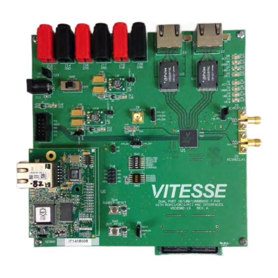
The following illustration shows the 501 VSC8502 Reference Board. Figure 2 • VSC8514 Evaluation Board (Bottom View) Additional VSC8502 collateral for both the VSC8502 device and VSC8502 reference design, including schematics, layout, GUI, and application notes can be found on the VSC8502 product web page at: www. vitesse.com/products/product/VSC8502... -
Page 5: General Description
VSC8502 Reference Board General Description The evaluation board, shown in Figure 1, provides the user a way to evaluate the VSC8502 device in multiple configurations. Two RJ-45 connectors are provided for copper media interfaces. The MAC interface (RGMII) is exposed via 0.1 inch steakheaders, J31 - J53. For standalone access to all of the features of the device, an external microcontroller is used to configure the VSC8502 via the MDIO bus. -
Page 6: Software Interface Microcontroller Card
VSC8502RD board, there are three on-board regulators that will convert the 5 V supplied by the PC to 1.0 V and 2.5 V for the VSC8502 and 3.3 V for other devices. For the VSC8502RD-VR board, there is only one on-board regulator that will convert the 5 V supplied by the PC to 3.3 V for the VSC8502’s internal voltage regulators, VSC8502’s 3.3 V digital supplies, as well as other devices. -
Page 7: Quick Start
Note: For proper device operation, prior to powering the board, ensure the NRESET input to the VSC8502 through SW1 is in the low state (right position). After connecting the USB cable which supplies power, toggle the NRESET input to the high state (left position) then back to the high state (left position). -
Page 8: Board Initialization
Note that the board is designed and laid out such that the RGMII DATA, CONTROL and CLOCK for each direction are matched in length approximately within +/-200 ps. vsc8502_RGMII_2nsGTXCLKdelay.txt: configure the MAC interface to RGMII mode with 2.0ns VPPD-03822 VSC8502 User Guide Revision 1.0... -
Page 9: Copper Media Operation (Auto-Negotiation Enabled)
RGMII configuration scripts. Configure auto-negotiation as per above and re-start ANEG (MII bit 0.12) The linkup bit is in MII Reg 1, bit 2 (MII 1.2), read it twice to update Traffic should now be flowing. VPPD-03822 VSC8502 User Guide Revision 1.0... -
Page 10: Useful Test Features
23.3 to 1. Transmitter Test Mode 1000BASE-T PMA test control can be configured through reg.9.15:13. Please refer to PMA Test application note for additional information in regard to performing the PMA conformance test. VPPD-03822 VSC8502 User Guide Revision 1.0... - Page 11 Microsemi. It is the Buyer's responsibility to independently determine suitability of any products and to test and verify the same. The information provided by Microsemi hereunder is provided "as is, where is" and with all faults, and the entire risk associated with such information is entirely with the Buyer.
Need help?
Do you have a question about the VSC8502 and is the answer not in the manual?
Questions and answers