Carefree PARAMOUNT Service Manual
2-stage multi-position awning
Hide thumbs
Also See for PARAMOUNT:
- Service manual (35 pages) ,
- Installation manual (23 pages) ,
- Owner's manual (16 pages)
Table of Contents
Advertisement
Quick Links
RV
Read this manual before servicing this product. Failure to follow the instructions and
safety precautions in this manual can result in personal injury and/or cause the product to
not operate properly.
For LED replacement parts and service procedures refer to 070013-301 "LED Service Manual for
Box Awnings" available on-line at
052548-301r13
www.carefreeofcolorado.com
Printed in USA
S
ERVICE
P
ARAMOUNT
2-Stage Multi-Position Awning
M
ANUAL
November, 2018
Advertisement
Table of Contents

Subscribe to Our Youtube Channel
Related Manuals for Carefree PARAMOUNT


Summary of Contents for Carefree PARAMOUNT
- Page 1 ERVICE ANUAL ARAMOUNT 2-Stage Multi-Position Awning Read this manual before servicing this product. Failure to follow the instructions and safety precautions in this manual can result in personal injury and/or cause the product to not operate properly. For LED replacement parts and service procedures refer to 070013-301 “LED Service Manual for Box Awnings”...
- Page 2 ROPRIETARY TATEMENT The Paramount Awning is a product of Carefree of Colorado, located in Broomfield, Colorado, USA. The information contained in or disclosed in this document is considered proprietary to Carefree of Colorado. Every effort has been made to ensure that the information presented in the document is accurate and complete.
-
Page 3: Table Of Contents
Carefree of Colorado Service Manual ARAMOUNT ABLE OF ONTENTS Product Overview .......................... 2 Paramount Patio Awning Specifications ..................... 2 Standard System Adjustments ....................3 Setting the Motor Limits .......................... 3 OUT Limit Switch ..........................3 IN Limit Switch ............................ -
Page 4: Product Overview
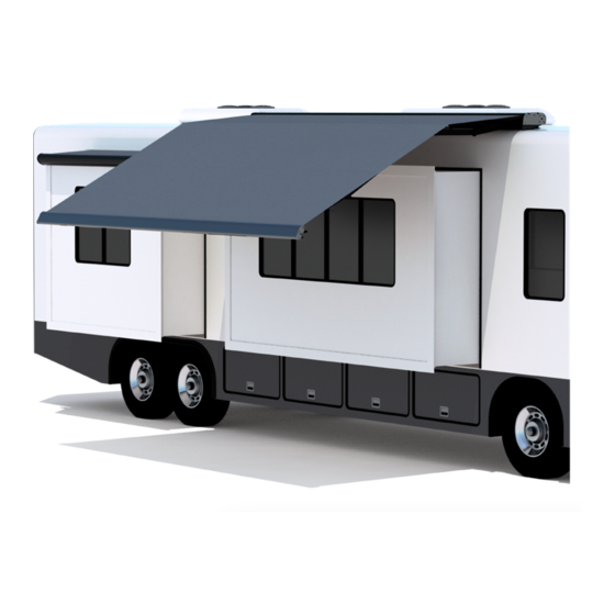
RODUCT VERVIEW The Paramount Patio Awning offers the coach owner an awning system that provides as much or as little shade as required. The canopy is housed in an aluminum case that easily blends in with the coach roof. Each unit is equipped with lateral support arms that are the strongest available on the market. No vertical arms interfere with coach sidewalls or equipment that may be mounted on the roof. -
Page 5: Standard System Adjustments
Carefree of Colorado Service Manual ARAMOUNT TANDARD YSTEM DJUSTMENTS ETTING THE OTOR IMITS The “ ” limit switch is used to stop the motor when the awning is fully extended. The “ ” limit is with the Direct Response system (see description below). -
Page 6: Awning Calibration Procedure
1. The controls are programmed with default awning calibration values; this allows full awning operation out-of-the-box. 2. The default calibration values are based on the average run times for the Paramount awning; these values are close but not perfect. 3. The Slide-Out Cover and Window awning intermediate positions are set as a percentage of the awning run time, 29% for Slide-Out Cover and 70% for Window. - Page 7 Carefree of Colorado Service Manual ARAMOUNT System Status Awning Power Stop Control On/Off OWER Motion Sensitivity Setting ATIO LEDs on Steady (Full Extend) Stop in Calibration Mode High Motion Sensor Press & Hold for 5 seconds KeyPad Remote Paramount012 NOTE: 4-awning keypad and remote shown. Description and procedures apply to all configurations.
-
Page 8: Adjusting The Lead Rail
Adjusting the Lead Rail Height The Paramount arms are installed and adjusted at the factory to operate at the tallest height possible. For multiple awning installations, the lead rails of adjacent awnings may appear to not align because of installation variables. -
Page 9: Manual Override
ANUAL VERRIDE If 110V power is not available to the coach, the Paramount awning can still be safely retracted using the manual override. The bypass is located inside the case, near the end cap. Remove the large rubber plug on top of the awning located toward the rear of the case on the motor side. -
Page 10: Programming The Rf Receiver For A Remote
Service Manual Carefree of Colorado ARAMOUNT RF R ROGRAMMING THE ECEIVER FOR A EMOTE When adding or replacing a remote control, it is necessary to program the transmitter and receiver. 1. Power to the control box must be on. 2. Locate the receiver box. -
Page 11: Standard Maintenance
Carefree of Colorado Service Manual ARAMOUNT TANDARD AINTENANCE Maintaining a Carefree Awning is easy. Just follow these basic steps: Always operate the awning according to the instructions. Periodically check that the fasteners are tight. Tighten if necessary. ... -
Page 12: Canopy Replacement
Service Manual Carefree of Colorado ARAMOUNT ANOPY EPLACEMENT During the following instructions, use the manual override procedure on page 6 to open and close the awning. 1. Disconnect power to the awnings. Tie the Elbows of the Outer Short Arms 2. -
Page 13: Motor Replacement
Carefree of Colorado Service Manual ARAMOUNT OTOR EPLACEMENT WARNING Shock Hazard. Always disconnect battery or power source before working on or around the electrical system. Important Note: The current replacement motor has a slightly different configuration for the limit switch locations. - Page 14 Service Manual Carefree of Colorado ARAMOUNT 8. Assemble the new motor: NOTE: The new and old motor components are not interchangeable. 8.1. Slide the crown onto the motor. NOTE: For VS configurations, use the new crown that is included with the motor.
-
Page 15: Modifying The Top Cover
Carefree of Colorado Service Manual ARAMOUNT ODIFYING THE OVER When replacing an older configuration motor with the current motor, it is necessary to modify the top cover access holes for the limit switches. Ø 3/8" Hole (x2) Ø 3/8" Hole (x2) 1. -
Page 16: Short Spring Arm Replacement
IMPORTANT NOTE: The outer short arms are provided as a set. For correct awning operation, both the outer arms must be replaced at the same time. NOTE: Two styles of case knuckles are used on the Paramount short arms. Early units use the 1-piece knuckle. Later models use the knuckle with positioning pins. -
Page 17: Installing The New Arm
Carefree of Colorado Service Manual ARAMOUNT Installing the New Arm The new arm is banded in the closed position. Do not remove the binding until instructed to do so. 1. (Refer to Detail C) Attach the knuckle on the new arm using the rotation pin removed previously. -
Page 18: Long Spring Arm Replacement
Service Manual Carefree of Colorado ARAMOUNT NOTICE Never attempt to adjust or alter the middle rail and attached components. Never attempt to move or adjust the arm knuckles in the case or on the middle rail; these have been pre- set at the factory for optimum operation. -
Page 19: Removing The Awning
ARAMOUNT EMOVING THE WNING CAUTION The Paramount awning is extremely heavy. Moving and/or lifting the awning requires a minimum of 3 people. The use of a lifting device is strongly recommended. 1. Retract the awning completely. 2. Disconnect power to the awning. -
Page 20: Diagnostic Tests
Service Manual Carefree of Colorado ARAMOUNT IAGNOSTIC ESTS The following procedures are intended to aid the service technician to logically resolve operational issues with the Direct Response installation. WARNING Shock Hazard. Always disconnect battery or power source before working on or around the electrical system. -
Page 21: Testing The System
Carefree of Colorado Service Manual ARAMOUNT ESTING THE YSTEM All function buttons are press ON. The auto-functions continue until the awning is fully extended or retracted. Pressing the button a second time will stop the function (does not apply to the "Extend All" or Retract All"... - Page 22 Service Manual Carefree of Colorado ARAMOUNT In the charts below, YES is a positive response to the test; NO is a negative response. HE AWNING OPERATE DIFFERENT THAN THE SWITCH MARKINGS The power switch at the key pad must be on; the LED will be illuminated if power is present.
- Page 23 Carefree of Colorado Service Manual ARAMOUNT WNING PERATE NOTE: The awnings are programmed sequentially (i.e. #1, #2, #3, #4). If power is missing from an awning, the subsequent awnings will not function (i.e. #1 and #2 works, #3 and #4 don't). Check the power to the first non functioning control board in sequence (i.e.
- Page 24 Service Manual Carefree of Colorado ARAMOUNT WNING DO NOT ETRACT URING WINDY CONDITIONS The Direct Response auto-retract system operates by gauging the motion of the awning's leading edge, not by the direct wind speed. Refer to the description in the owner's manual.
-
Page 25: Electronics
Carefree of Colorado Service Manual ARAMOUNT LECTRONICS – S IRING IAGRAM INGLE WNING Ignition Switched +12VDC Receiver Awning #1 12VDC Ignition Ground Sensor Lockout Sensor (Optional) Splitter Key Pad Remote Key Pad To 110VAC NOTES: Detail Wire Legend: For RH Configuration Black Reverse Red &... -
Page 26: Wiring Diagram - 2-Awnings
Service Manual Carefree of Colorado ARAMOUNT – 2-A IRING IAGRAM WNINGS Receiver Awning #1 Sensor 3 Conductor 14AWG NM Wire w/ Gnd Awning #2 Sensor Key Pad 3 Conductor 14AWG NM Wire w/ Gnd Remote Ignition Switched Key Pad +12VDC... -
Page 27: Phone Cord Connection
Carefree of Colorado Service Manual ARAMOUNT NOTES: Wire Legend: Black White Green (Ground) Awnings #1 & #4 shown as LH Motor, Awnings #2 & #3 shown as RH Motor For LH Motor Configurations: Motor Red goes to Pin (1); Motor Black goes to Pin (2) For RH Motor Configurations: Motor Red goes to Pin (2);... -
Page 28: Wiring Diagram - 4 Awnings
Service Manual Carefree of Colorado ARAMOUNT – 4 A IRING IAGRAM WNINGS Receiver Awning #1 Sensor 3 Conductor 14AWG NM Wire w/ Gnd Awning #2 Sensor 3 Conductor 14AWG NM Wire w/ Gnd Key Pad Remote Ignition Switched Key Pad... - Page 29 Carefree of Colorado Service Manual ARAMOUNT NOTES: Wire Legend: Black White Green (Ground) Awnings #1 & #4 shown as LH Motor, Awnings #2 & #3 shown as RH Motor For LH Motor Configurations: Motor Red goes to Pin (1); Motor Black goes to Pin (2) For RH Motor Configurations: Motor Red goes to Pin (2);...
-
Page 30: Connection Flex W/ "110Vdr" Control Boxes
Motor 4 CR024 2. The RF Receiver and the optional ignition lock-out can be plugged into any unused "EYE" port. 3. The "110VDR" control boxes are compatible with integrator interfaces. Contact Carefree engineering for information and system requirements. PTIONAL ANUAL... -
Page 31: Sensor Replacement
Carefree of Colorado Service Manual ARAMOUNT ENSOR EPLACEMENT The replacement sensor is furnished with a 25 foot cable. The cable is furnished in case the installed cable has been damaged or compromised. NOTICE Do Not attempt to cut and splice the cable. If damaged, the cable must be replaced to ensure system integrity. -
Page 32: Part Number Listing
HS Configuration Canopy construction with Canopy construction with vertical seams (previous) horizontal seams (current) Original Motor Configuration There are two configurations of the Paramount (Silver Body) based on the canopy construction as shown above. (VS Configuration) (HS Configuration) Paramount501a 052548-301r13... - Page 33 Carefree of Colorado Service Manual ARAMOUNT Item Part Number Description Notes GJ001 Mounting Plate Kit, Flat GJ002 Mounting Plate Kit, 3˚ R001376 End Plate Assy, LH, Idler R001375 End Plate Assy, LH, Motor R001377 End Plate Assy, RH, Motor R001378...
-
Page 34: Electronic Components
Service Manual Carefree of Colorado ARAMOUNT Electronic Components Single 2-Awning 4-Awning Paramount501 Item Part Number Description Notes R060633-001 Control Box 110VDR R060618-001 Key Pad Single Awning R060624-001 Remote, 433 MHz Single Awning R060633-002 Control Box, Motor 1 & 2 110VDR... - Page 35 Carefree of Colorado Service Manual ARAMOUNT NOTES: 052548-301r13...
- Page 36 Service Manual Carefree of Colorado ARAMOUNT NOTES: 052548-301r13...
Need help?
Do you have a question about the PARAMOUNT and is the answer not in the manual?
Questions and answers