Carefree PARAMOUNT Installation Manual
2-stage multi-position awning
Hide thumbs
Also See for PARAMOUNT:
- Service manual (36 pages) ,
- Installation manual (21 pages) ,
- Owner's manual (16 pages)
Table of Contents
Advertisement
Quick Links
RV
Read this manual before installing or servicing this product. Failure to follow the
instructions and safety precautions in this manual can result in personal injury and/or
cause the product to not operate properly.
T
C
ABLE OF
ONTENTS
Product Overview .......................................................................................................................... 1
Paramount Patio Awning Specifications ................................................................................................. 1
Component Checklist.............................................................................................................................. 2
Installation - Mechanical .............................................................................................................. 4
Required Pre-Installation Parameters ..................................................................................................... 4
Mounting Plate Layout and Installation ................................................................................................... 5
Mounting the Awning Unit ....................................................................................................................... 5
Installation - Electrical .................................................................................................................. 6
Key Pad Installation ................................................................................................................................ 6
Control Box Installation ........................................................................................................................... 7
Installing the Remote Receiver ............................................................................................................... 8
Ignition Lockout Sensor Installation (Optional) ....................................................................................... 9
Wiring Diagram - Single Awning .......................................................................................................... 10
Wiring Diagram - 2-Awnings ................................................................................................................ 11
Wiring Diagram - 4 Awnings ................................................................................................................ 13
Connection Flex w/ "110VDR" Control Boxes ...................................................................................... 15
Optional Manual Bypass Switch ........................................................................................................... 15
Switch Installation - LED Lighting ......................................................................................................... 16
Testing the System ............................................................................................................................... 17
Standard System Adjustments .................................................................................................. 18
Awning Calibration Procedure .............................................................................................................. 18
Setting the Motor Limits ........................................................................................................................ 20
Adjusting the Lead Rail Height ............................................................................................................. 21
Manual Override ................................................................................................................................... 21
052548-001r11
I
NSTALLATION
2-Stage Multi-Position Awning
Printed in USA
M
ANUAL
P
ARAMOUNT
November, 2018
Advertisement
Table of Contents

Related Manuals for Carefree PARAMOUNT


Summary of Contents for Carefree PARAMOUNT
-
Page 1: Table Of Contents
ABLE OF ONTENTS Product Overview .......................... 1 Paramount Patio Awning Specifications ....................1 Component Checklist..........................2 Installation – Mechanical ......................4 Required Pre-Installation Parameters ..................... 4 Mounting Plate Layout and Installation ....................5 ... - Page 2 ROPRIETARY TATEMENT The Paramount Patio Awning is a product of Carefree of Colorado, located in Broomfield, Colorado, USA. The information contained in or disclosed in this document is considered proprietary to Carefree of Colorado. Every effort has been made to ensure that the information presented in the document is accurate and complete.
-
Page 3: Product Overview
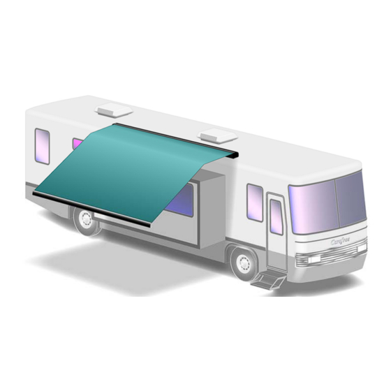
RODUCT VERVIEW The Paramount Patio Awning offers the coach owner an awning system that provides as much or as little shade as required. The canopy is housed in an aluminum case that easily blends in with the coach roof. Each unit is equipped with lateral support arms that are the strongest available on the market. No vertical arms interfere with coach sidewalls or equipment that may be mounted on the roof. -
Page 4: Component Checklist
Carefree of Colorado Installation Manual ARAMOUNT OMPONENT HECKLIST Single Awning Electronics Dual Awning Electronics 4-Awning Electronics OF F Paramount002 052548-001r11... - Page 5 Carefree of Colorado Installation Manual ARAMOUNT I ESCRIPTION Awning Assembly Mounting Bracket Screw, Thread Cutting 3/8 x 1 1/2 Screw, Hex Head 5/16-18 x 2 Square Nut 5/16-18 Hex Key 7mm x 133mm ...
-
Page 6: Installation - Mechanical
ARAMOUNT – M NSTALLATION ECHANICAL The following instructions are for the physical installation of one Paramount awning. Repeat the instructions for each awning to be installed. NOTE: When installing a multiple awning system, the awnings must be separated by a minimum of 4". -
Page 7: Mounting Plate Layout And Installation
Carefree of Colorado Installation Manual ARAMOUNT OUNTING LATE AYOUT AND NSTALLATION The Paramount Patio Unit is mounted using four (4) 22” mounting brackets. L (Awning Length) Top View 9” (typ) 8” (typ) 3” (typ) L (feet) A (inches) B (inches) C (inches) D (inches) 8”... -
Page 8: Installation - Electrical
Carefree of Colorado Installation Manual ARAMOUNT – E NSTALLATION LECTRICAL WARNING Shock Hazard. Always disconnect battery or power source before working on or around the electrical system. IMPORTANT NOTICES: Failure to follow the wiring instructions in this publication may void the warranty. -
Page 9: Control Box Installation
Carefree of Colorado Installation Manual ARAMOUNT ONTROL NSTALLATION NOTE: a) For Multiple Awning Installations: The awning motor connected to the controller board marked "motor #1" will correspond with "Awning 1" on the key pad control and remote. The awning motor connected to "motor #2"... -
Page 10: Installing The Remote Receiver
Carefree of Colorado Installation Manual ARAMOUNT NSTALLING THE EMOTE ECEIVER Determine the location of the RF receiver: 1.1 Do not mount the unit near heat producing elements such as LP appliances or engine exhaust components. 1.2 For best reception, do not mount the unit near or on a metal surface. -
Page 11: Ignition Lockout Sensor Installation (Optional)
Carefree of Colorado Installation Manual ARAMOUNT GNITION OCKOUT ENSOR NSTALLATION PTIONAL Two ignition lockout sensors are available with the Direct Response System. The STD ignition lockout module disables the extend function when the module receives a current through a switched 12VDC circuit.. -
Page 12: Wiring Diagram - Single Awning
Carefree of Colorado Installation Manual ARAMOUNT – S IRING IAGRAM INGLE WNING Ignition Switched +12VDC Receiver Awning #1 12VDC Ignition Ground Sensor Lockout Sensor (Optional) Splitter Key Pad Remote Key Pad To 110VAC NOTES: Detail Wire Legend: For RH Configuration Black Reverse Red &... -
Page 13: Wiring Diagram - 2-Awnings
Carefree of Colorado Installation Manual ARAMOUNT – 2-A IRING IAGRAM WNINGS Receiver Awning #1 Sensor 3 Conductor 14AWG NM Wire w/ Gnd Awning #2 Sensor Key Pad 3 Conductor 14AWG NM Wire w/ Gnd Remote Ignition Switched Key Pad +12VDC... - Page 14 Carefree of Colorado Installation Manual ARAMOUNT NOTES: Wire Legend: Black White Green (Ground) Awnings #1 & #4 shown as LH Motor, Awnings #2 & #3 shown as RH Motor For LH Motor Configurations: Motor Red goes to Pin (1); Motor Black goes to Pin (2) For RH Motor Configurations: Motor Red goes to Pin (2);...
-
Page 15: Wiring Diagram - 4 Awnings
Carefree of Colorado Installation Manual ARAMOUNT – 4 A IRING IAGRAM WNINGS Receiver Awning #1 Sensor 3 Conductor 14AWG NM Wire w/ Gnd Awning #2 Sensor 3 Conductor 14AWG NM Wire w/ Gnd Key Pad Remote Ignition Switched Key Pad... - Page 16 Carefree of Colorado Installation Manual ARAMOUNT NOTES: Wire Legend: Black White Green (Ground) Awnings #1 & #4 shown as LH Motor, Awnings #2 & #3 shown as RH Motor For LH Motor Configurations: Motor Red goes to Pin (1); Motor Black goes to Pin (2) For RH Motor Configurations: Motor Red goes to Pin (2);...
-
Page 17: Connection Flex W/ "110Vdr" Control Boxes
2. The RF Receiver and the optional ignition lock-out can be plugged into any unused "EYE" port. It is not necessary to use the splitter as shown in the diagrams. 3. The "110VDR" control boxes are compatible with integrator interfaces. Contact Carefree engineering for information and system requirements. -
Page 18: Switch Installation - Led Lighting
NSTALLATION IGHTING Optional factory installed LED light strips are available for the Paramount awning. A strip can be mounted in the lead rail or in the case or both. For lead rail installations, the harness is routed through the awning with the Direct Response cable. -
Page 19: Testing The System
Carefree of Colorado Installation Manual ARAMOUNT ESTING THE YSTEM All function buttons are press ON. The auto-functions continue until the awning is fully extended or retracted. Pressing the button a second time will stop the function (does not apply to the "Extend All" or Retract All"... -
Page 20: Standard System Adjustments
1. The controls are programmed with default awning calibration values; this allows full awning operation out-of-the-box. 2. The default calibration values are based on the average run times for the Paramount awning; these values are close but not perfect. 3. The Slide-Out Cover and Window awning intermediate positions are set as a percentage of the awning run time, 29% for Slide-Out Cover and 70% for Window. - Page 21 Carefree of Colorado Installation Manual ARAMOUNT System Status Awning Power Stop Control On/Off OWER Motion Sensitivity Setting ATIO LEDs on Steady (Full Extend) Stop in Calibration Mode High Motion Sensor Press & Hold for 5 seconds KeyPad Remote Paramount012 NOTE: 4-awning keypad and remote shown. Description and procedures apply to all configurations.
-
Page 22: Setting The Motor Limits
Carefree of Colorado Installation Manual ARAMOUNT ETTING THE OTOR IMITS The motor limit switches are preset at the factory for best operation. The “ ” limit switch is used to stop the motor when the awning is fully extended. The “... -
Page 23: Adjusting The Lead Rail Height
DJUSTING THE EIGHT The Paramount arms are installed and adjusted at the factory to operate at the tallest height possible. For multiple awning installations, the lead rails of adjacent awnings may appear to not align because of installation variables. The height of the high lead rail may be lowered with the procedure below. This is not a pitch adjustment.
Need help?
Do you have a question about the PARAMOUNT and is the answer not in the manual?
Questions and answers