Table of Contents
Advertisement
Quick Links
Advertisement
Table of Contents

Subscribe to Our Youtube Channel
Related Manuals for Spacelabs BleaseSirius

Summary of Contents for Spacelabs BleaseSirius
- Page 1 BleaseSirius Anesthetic Machine Technical Manual 073-0227-00/REV. D...
- Page 3 With 700/900 Series Ventilators Technical Manual MODIFICATIONS LABEL PR023288 PR032030 PR033225 PR034475 Spacelabs Healthcare Ltd. 1 Harforde Court • John Tate Road • Hertford SG13 7NW • United Kingdom Tel: +44 (0)1992 507700 Fax: +44 (0)1992 501213 e-mail (enquiries): advsales@spacelabs.com Part Number: 073-227-00 e-mail (technical): advsupport@spacelabs.com...
- Page 5 For all users and Service Personnel, refer to the User Manual before operating the machine. © Copyright 2013, Spacelabs Healthcare Limited. All rights reserved. The information contained in this publication may not be used for any other purpose than that for which it was originally supplied.
- Page 6 This page is intentionally left blank...
-
Page 7: Table Of Contents
Contents Chapter 1-Technical Description ............... 19 1.1 Description ......................21 1.1.1 General ....................21 1.1.2 The Frame ....................21 1.1.3 Pneumatic Assembly ................21 1.1.4 The Monitor Shelf .................21 1.2 Specifi cation ......................24 1.2.1 Machine Dimension................24 1.2.2 Work Surface Dimensions ..............24 1.2.3 Monitor Shelf Dimensions ..............24 1.2.4 Maximum Loading ................24 1.3 Pneumatics ......................25... - Page 8 Backbar Seals ..................48 3.2.4 Backbar Dzus Springs................48 3.2.5 Absorber Stop/’O’ Ring ................48 3.2.6 Pipeline Fitting and ‘O’ Ring ..............48 3.3 AGSS Probe and Float for Spacelabs AGSS PN 14200018, (if Fitted) ..............50 3.4 Bellows Base/Canister ..................51 3.5 Pop-off Valve ......................51...
- Page 9 Contents 3.6 Absorber ......................53 3.6.1 Valve Covers ..................53 3.6.2 Manometer ...................53 3.6.3 Canister Seals ..................53 3.6.4 Fitting 4 Year Planned Maintenance Kit, PN 14000512 .......54 3.6.5 Ventilator Filter ..................54 3.6.5.1 Two Valve Version Only (on units before Feb 2009) ......54 3.6.5.1 Valve Block on units after Feb 2009 ............54 3.6.6 Cylinder Regulator Pressure Relief Valve, PN 019-0831-00 ....55...
- Page 10 4.14.3 APL Valve Check ..................81 4.15 Ventilator Test ....................83 4.16 Vaporizer Output Concentration Check ............89 4.17 Electrical Safety Test ..................91 4.18 Complete the BleaseSirius Checkout Sheet ..........92 Chapter 5-Detailed Repair Procedures ............. 93 5.1 Removal/Replacement Instructions..............95 5.1.1 Removal of Outer Cases (on units up to Jan 2009) ......95 5.1.2...
- Page 11 Contents 5.9.2 On units Manufactured After Feb 2009Feb 2009 onwards) ....132 5.10 Oxygen Flush & Common Gas Outlet Safety Valve Adjustment (up to Feb 2009) ................133 5.10.1 Oxygen Flush Adjustment on units sold before July 2010 (Units sold after July 2010 are not adjustable.) ........134 5.10.2 Common Gas Outlet (CGO) Removal/ Replacement (From Feb 2009 onward) ..............135...
- Page 12 Contents 5.19.8 Removal of Switch Mode Power Supply (FR136025) ......182 5.19.9 Removal of Flow Control Valves (up to March 2009) ......183 5.19.10 Removal of Gas Inlet Module (FR 140026) (up to March 2009) ..184 5.19.11 Replacement of Battery (80300025) ..........185 5.19.12 Exchanging of Fuses (EF533789)............186 5.20 Major Component Installation ..............187...
- Page 13 9.5 Technology Disclaimer / Tamper Proof Seal ..........256 9.6 Note to Service Personnel ................256 9.7 CE Mark 257 9.8 Trademarks and Acknowledgements ............258 9.9 Hazard Notices....................259 9.9.1 BleaseSirius Warnings ...............260 9.9.2 Electrostatic Sensitive Devices (ESD) Warnings and Cautions ..262 9.9.3 Cautions .....................263 9.9.4 Ventilator Warnings ................264...
- Page 14 Figure 6 - Pneumatic Circuit ..................40 Figure 7 - BleaseSirius Annual Planned Maintenance Kit PN 14000511 ..................46 Figure 8 - BleaseSirius Four Year Planned Maintenance Kit PN 14000512 ....47 Figure 9 - Pipeline Fitting & ‘O’ Ring................49 Figure 10 - AGSS .....................50 Figure 11 - Pop-off Valve ....................51...
- Page 15 Figures Figure 39 - Connect a Flow Measuring Device ............84 Figure 40A - Change the Flow Sensor Settings ............85 Figure 40B - Pedi Sensor Placement setting..............85 Figure 41 - Connect a Pressure Measuring Device............86 Figure 42 - Step 5: Connect a Reusable Tube ............89 Figure 43 - Connect a Pressure Sample Tee .............90 Figure 44 - Gas Analyzer Connection ................90 Figure 45 - Removal of Top Surface ................95...
- Page 16 Figures Figure 77 - Assemble the Spring, Spring Rest and Bonnet ........126 Figure 78 - Slip Ring Location ..................126 Figure 79 - Diaphragm Assembly ................126 Figure 80 - Fit the Actuator Assembly ..............127 Figure 81 - Attach the Bonnet to the Regulator ............127 Figure 82 - Fit the Relief Valve to the Regulator ............128 Figure 83 - Location of Valve Retaining Screws ............129 Figure 84- Backbar Valve ..................129...
- Page 17 Figures Figure 116 - Absorber Molding 03 ................156 Figure 117 - Absorber Molding 04 ................156 Figure 118 - Internal view of Absorber Moldings ............157 Figure 119 -Valve Arc ....................157 Figure 120 - Bellows Interface Gasket Fixing Screws ..........158 Figure 121 - Gasket Removed .................158 Figure 122 - Drawer Mechanism ................164 Figure 123 - Location of Drawer Mechanism and Removal ........165 Figure 124 - Drawer Mechanism ................166...
- Page 18 List of Schematics Figure 156 - Banjo Fitting ..................212 Figure 157 - Hypoxic Guard Retaining Screws ............213 Figure 158 - Screen Retaining Screws ..............214 Figure 159 - Screen-Circuit Board Connectors (3) ...........215 Figure 160 - Circuit Board Screws (6) ..............217 Figure 161 - Flow Sensor ..................218 Figure 162 - Software Update Panel ................220 Figure 164 - Exit Panel .....................222...
-
Page 19: Chapter 1-Technical Description
BleaseSirius Anesthetic Machine Chapter 1 Technical Description... - Page 20 Technical Description...
-
Page 21: Description
In US markets, use a cord fi tted with a NEMA 5-15 hospital grade plug to connect the BleaseSirius to the mains supply. Connection of equipment to the auxiliary mains socket outlets may increase leakage currents to values exceeding the... -
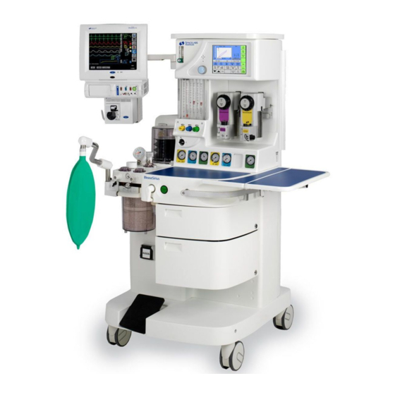
Page 22: Figure 1 - Bleasesirius Anesthetic Machine
Technical Description Figure 1 - BleaseSirius Anesthetic Machine... - Page 23 Technical Description Figure 1 Key Monitor shelf Ventilator Vaporizer Cylinder/pipeline gauges Pneumatic unit - (behind gauge panel) Handle Oxygen fl ush Common gas outlet (or option A.C.G.O.) Drawer Frame Brake Pedal Absorber Bag Arm Link Pipe Adjustable Bag Arm Main On/Off Switch Suction Controller Flow Control Valves with Hypoxic Guard Flowblock Assembly...
-
Page 24: Specifi Cation
Technical Description 1.2 Specifi cation 1.2.1 Machine Dimension Height Max. Width Depth Average Weight 1486mm / 158.5” 705mm / 27.7” 747mm / 29” 110kg / 242.5lbs 1.2.2 Work Surface Dimensions Height Area 854mm / 33.6” 98612.2mm / 152.8” 1.2.3 Monitor Shelf Dimensions Height Area 1486mm/58.5”... -
Page 25: Pneumatics
Technical Description 1.3 Pneumatics 1.3.1 Gas-Specifi c Color Specifi cations ANSI Oxygen White Green Nitrous Oxide Blue Blue MED AIR Black Yellow 1.3.2 Gas Supply Combinations Max No. of Gases Max No. of Cylinders Max No. of Pipelines Max No. of Gauges Max Cylinder Size (using PIV Index) Large Cylinder Kit Max. -
Page 26: Technical/Performance Specifi Cation
Accepts Selectatec Hypoxic gases Minimum 21% oxygen/nitrous oxide mixture allowed 1.4.2 Ventilator A Blease700/900 ventilator is built into the BleaseSirius. 1.4.3 Alarms / Indicators Oxygen failure Audible alarm sounds for minimum of 8 secs when oxygen pressure falls below 30 psi. -
Page 27: Electrical
Technical Description 1.4.5 Electrical Voltage 100 / 230 V Frequency 60 / 50 Hz Power 1.2 / 1.0 kVa The auxiliary sockets are numbered 1 through 4, top to bottom and are rated as in the following tables. If the machine has the switching sockets option, sockets 3 and 4 will switch On and Off when the Main On/Off (Figure 1, Key O) is switched On and Off, rather than with the Mains On/Off switch (Figure 2). -
Page 28: Supplies
Technical Description 1.4.6 Supplies , MED AIR, N O pipeline Nominal pressure 400 kPa/58.0 psi, minimum 275 kPa/39.8 psi, maximum 482 kPa/69.9 psi Auxiliary pneumatic outlets MED AIR or O - 400 kPa/58.0 psi at zero fl ow. 80 l/m max. fl ow Auxiliary Oxygen Outlet 0-15 lpm 1.4.7... -
Page 29: Chapter 2-Overview
BleaseSirius Anesthetic Machine Chapter 2 Overview... - Page 30 Overview...
-
Page 31: Description Of The Ventilator
Overview 2.1 Description of the Ventilator 2.1.1 Overview 2.1.1.1 PEEP The Blease700/900 series ventilator continuously monitors and displays the Positive End Expiratory Pressure (PEEP). default, PEEP 2 - 4 cmH O is introduced to the circuit, caused bellows assembly, which is shown as OFF. A PEEP value between 3 and 20 cmH O can be set from the panel, with an automatic alarm... -
Page 32: Trigger
Overview 2.1.1.2 Trigger The level of negative fl ow caused by the patient’s attempt to breathe before the ventilator initiates fl ow to assist the patient with the spontaneous breath. Range: 1 to 15 l/m all modes (SIMV + PSV and Pressure Support). 2.1.1.3 Support Pressure Breathing circuit pressure level for assistance with patient’s spontaneous breath. -
Page 33: I:e Ratio
Overview 2.1.1.10 I:E Ratio The ratio of the inspiratory time to the expiratory time. Range: 2.0:1 to 1:5.0, all modes in steps of 0.1. 2.1.1.11 Pressure Limit The breathing system maximum pressure limit. Range: 10 cmH O to 50 cmH O Pediatric. -
Page 34: Pre-Use Test
Overview 2.2 Pre-use Test 2.2.1 Fresh Gas Fresh gas (FG) fl ow adds to the delivered Tidal Volume (TV) during the inspiratory period. To compensate, the delivered volume must be reduced. The formula for this reduction is: Effective TV = TV - TV due to FG =TV - ((FG fl... - Page 35 Overview Switch the unit ON. The compliance menu will be displayed. The patient airway fl ow sensor head must be in the patient circuit in order to carry out compliance compensation. Select Yes to Compliance Compensation and follow the instructions on screen instructions The ventilator delivers a breath of known volume to the breathing circuit, records the pressure (cmH...
-
Page 36: Compensation
Overview To calculate the increase in TV: 500mL = 25 20cmH The 735ml is the actual ventilator output into the breathing circuit to give 500ml at the catheter mount. The value must be recalculated every time volume controlled ventilation starts. = 735mL new TV = 500 * 2.2.3... -
Page 37: Mode Dependant Features
Overview 2.2.4 Mode Dependant Features PRESSURE PRESSURE VOL/ PRESSURE SIGH PAUSE SUPPORT SUPPORT FLOW LIMIT TRIGGER PRESSURE Meas/ Pressure V O L U M E Limit CONTROL Pressure PRESSURE ALWAYS ALWAYS Meas Meas Meas Limit SUPPORT Meas/ Meas/ Meas/ Pressure SIMV-VC ALWAYS ALWAYS... -
Page 38: Figure 4 - Ventilator Schematic
Overview Figure 4 - Ventilator Schematic... -
Page 39: Figure 5 - Absorber Pneumatic Schematic
Overview Manometer APL Exhaust Valve Inspiratory Non-return Valve Fresh Gas Port Patient Inspiratory Connector Bag/Vent Valve Patient Expiratory Connector Bag Port Expiratory Non-return Valve Bellows Canister(s) Pop-Off Valve APL Valve Ventilator Drive Gas Oxygen Sensor Port Pop-Off Exhaust Bypass Switch Figure 5 - Absorber Pneumatic Schematic... -
Page 40: Figure 6 - Pneumatic Circuit
Overview Air Pipeline Vent Supply Air Cylinder Yoke Air Secondary Regulator O Pipeline O Secondary Regulator O Cylinder Yoke Oxygen Secondary Regulator Pipeline Oxygen Flush Cylinder Yoke Air Flowmeter Reservoir O Flowmeter Auxiliary Flowmeter Hypoxic Protection Link System High Pressure Outlet Oxygen Flowmeter Air Takeover Valve Pressure Relief Valve... -
Page 41: Principles Of Operation
Overview 2.3 Principles of Operation For active inspiration, the fl ow control valve is opened to provide a specifi c gas fl ow into the bellows assembly. Simultaneously, the expiratory solenoid closes and pressure is generated in the bellows assembly producing an inspiratory fl... - Page 42 Notes...
-
Page 43: Chapter 3-Planned Maintenance
BleaseSirius Anesthetic Machine Chapter 3 Planned Maintenance... - Page 44 Planned Maintenance...
-
Page 45: Planned Maintenance
14000512 * Includes all parts required for units with four cylinder yokes installed. All parts included in PN 14000512 are not required for all BleaseSirius machines. You can order idividual parts instead of ordering PN 14000512. Four-Year PM Kit Contents... -
Page 46: Figure 7 - Bleasesirius Annual Planned Maintenance Kit
Pop off • Absorber Upper Seal • Absorber ‘O’ Rings for Insp/ Exp + APL • Pop off Valve • Absorber Gauge • Absorber Control Seal • Absorber Bottom Canister Figure 7 - BleaseSirius Annual Planned Maintenance Kit PN 14000511... -
Page 47: Figure 8 - Bleasesirius Four Year Planned Maintenance Kit Pn 14000512
Planned Maintenance • Cylinder Regulator Service Kit • ‘O’ Ring for Filter • Battery Note: Includes annual kit, PN 14000511 Figure 8 - BleaseSirius Four Year Planned Maintenance Kit PN 14000512... -
Page 48: Routine Maintenance And Service Check
3.2.6 Pipeline Fitting and ‘O’ Ring Disconnect pipelines from their supply. Disconnect the pipeline connection from the BleaseSirius. Unscrew the two small grub screws until the main body of the connection is free to rotate. Unscrew the connector, the fi lter and ‘O’ Ring can now be changed. -
Page 49: Figure 9 - Pipeline Fitting & 'O' Ring
Planned Maintenance Refi t the outer part of the connector and tighten the two small grub screws. Repeat for all three pipelines. Note each gas type has a unique fi tting and can not be incorrectly mixed. Refi t the pipeline and check for leaks. Figure 9 - Pipeline Fitting &... -
Page 50: Agss Probe And Float For Spacelabs Agss
Planned Maintenance 3.3 AGSS Probe and Float for Spacelabs AGSS PN 14200018, (if Fitted) The AGSS is not available in the U. S.) Disconnect electrical supply to BleaseSirius Remove the bellows assembly by sliding the absorber forward until the bellows connections become free, then remove the two thumb wheels at the front of “O’... -
Page 51: Bellows Base/Canister
Planned Maintenance 3.4 Bellows Base/Canister Remove the bellows cover (bayonet fi tting), then replace the bellows base/canister ‘O’ Ring. Remove the bellows by gently pulling the lower convolution of the retaining ring. Remove the pop-off valve. Replace the bellows base pop-off valve “O” ring. 3.5 Pop-off Valve Figure 11 - Pop-off Valve Replace Pop-off valve in bellows base. -
Page 52: Figure 12 - Bellows Assembly
Planned Maintenance A - Cover B - Bellows C - Pop-off valve D - Valve seat E - Fixing screws F - Bellows base G - O-ring Figure 12 - Bellows Assembly... -
Page 53: Absorber
Planned Maintenance 3.6 Absorber 3.6.1 Valve Covers When removing or refi tting any of these valves, it is important to ensure the metal valve disk and seat are not damaged. Remove the expiratory valve by twisting the clear plastic valve cover. Replace the ‘O’... -
Page 54: Fitting 4 Year Planned Maintenance Kit, Pn 14000512
Planned Maintenance 3.6.4 Fitting 4 Year Planned Maintenance Kit, PN 14000512 The recommended service intervals for the following are every 4 years. The following procedure outlines the steps taken to replace the parts included in the service kit 14200512. 3.6.5 Ventilator Filter 3.6.5.1 Two Valve Version Only (on units before Feb 2009) Ensure all gas supplies are disconnected. -
Page 55: Cylinder Regulator Pressure Relief Valve, Pn 019-0831-00
Planned Maintenance 3.6.6 Cylinder Regulator Pressure Relief Valve, PN 019-0831-00 Remove all cylinders. Remove the large back panel. Fit a service kit to each of the regulators. Disassembly Remove and discard relief valve by turning counter-clockwise using a 15/16” spanner or socket. Assembly Fit new relief valve and ‘O’... -
Page 56: Cleaning
Planned Maintenance 3.7 CLEANING Cleaning of external surfaces is possible using water or isopropyl alcohol. Cleaning of internal surfaces and parts should not be required and is not recommended. This product is intended for use in medical compressed gas systems only. Do not use this product where pressures and temperatures can exceed those listed under Technical Data. -
Page 57: Figure 14 - Primary Regulator
Planned Maintenance Adjusting Screw Locknut Spring Bonnet Upper Spring Rest Slip Ring Diaphragm Assembly Actuator Assembly Seal Ring Valve Cartridge ‘O’ Ring Body Mounting Spacer Relief Valve Figure 14 - Primary Regulator... - Page 58 Notes...
-
Page 59: Chapter 4-System Checks
BleaseSirius Anesthetic Machine Chapter 4 System Checks... - Page 60 System Checks...
-
Page 61: Overview
Flow measuring device (able to read 20 – 1000 ml) Oxygen analyzer Pressure Gauge (able to read 0 – 200 mmHg) 10. Copy of the BleaseSirius Checkout Sheet (See page 64). You can use a print copy (073-0301-00) or an electronic copy (073-0321-00). Contact Technical Support at advsupport@spacelabs.com... -
Page 62: Parts Required
System Checks Parts Required Description Part Number Quantity WHITE O2 DRV HOSE O2 NIST-UK 10700007 MINISCHRAEDER 0.32M BLACK AIR DRIVEHOSE AIR NIST-UK 10700008 MINISCHR. 0.32M GREEN O2 DRIVE HOSE O2 DISS-US DISS 10700009 0.32M CONNECTOR, 22MM FEMALE TO BARB, 376-0559-00 STAINLESS STEEL 9/16 O CLIP STD GAUGE ST2161... - Page 63 System Checks Description Part Number Quantity Pipeline Leak Test Valve, O2 DISS 010-1981-00 Pipeline Leak Test Valve, N2O DISS 010-1982-00 Pipeline Leak Test Valve, AIR DISS 010-1983-00 Note: Use PNs 010-1981-00, 010-1982-00 and 010-1983-00 for the Reverse DISS Pipeline Leak Test. Pipeline Leak Test Valve, O2 NIST 010-1984-00 Pipeline Leak Test Valve, N2O NIST...
-
Page 64: Figure 15 - Bleasesirius Checkout Sheet (Pn 073-0301-00 Rev. C)
System Checks Figure 15 - BleaseSirius Checkout Sheet (PN 073-0301-00 Rev. C) -
Page 65: Visual Inspection
System Checks 4.3 Visual Inspection Check that the following components are free of damage and are securely mounted to the machine and/or fi ttings. Cylinder Yokes Verify the yoke block, index pins and bridges are free of damage and that the tee screw freely threads into the yoke bridge. -
Page 66: Pipeline Leak Test
System Checks Flowmeter Assembly & Control Knobs Verify that the fl owmeter assembly and knobs are free of damage. Turn the knobs on and off to check for a smooth operation. 10. Drawers Verify that the drawer(s) are free of damage. Open and close the drawers to check for a smooth operation. -
Page 67: Figure 17 - N O Pipeline Gauge
System Checks Connect the appropriate pipeline hose to the pipeline test shut-off valve assembly, and then connect it to the hospital supply. Turn the pipeline test shut-off valve “ON” to allow fl ow. Verify that the appropriate gauge registers. Wait 15 seconds for the system to pressurize and shut the pipeline test shut-off valve off. -
Page 68: Cylinder Leak Test
System Checks 4.5 Cylinder Leak Test Ensure that all fl ow control valves are turned off. Ensure that the power switch is in the “OFF” position. Ensure that no pipeline supply is connected to the pipeline inlets. Fit a full O cylinder (at least 1000 psi) to the O yoke. -
Page 69: Figure 18 - Connect Pressure Measuring Device
System Checks Disconnect the 6 mm plug from the regulator test point, then connect a pressure measuring device to the test point. Figure 18 - Connect Pressure Measuring Device Turn the cylinder on. Turn the switch to the “ON” position and set a fl ow of 1 L/min on the fl ow control valve for the appropriate gas being tested. -
Page 70: On/Off Switch Gas Cut Off Test
System Checks 4.7 On/Off Switch Gas Cut Off Test Ensure that the power switch is in the “OFF” position. Ensure that a supply is connected to all pipeline inlets. While the switch is in the “OFF” position, check that no fl ow is available to the fl... -
Page 71: High Pressure Outlet Test
System Checks 4.9 High Pressure Outlet Test 4.9.1 Parts required Only order parts that are required for testing, depending on which high pressure outlet is fi tted to the machine. O2 Schraeder (White) Air Schraeder (Black) O2 DISS (Green) 10700007, Quantity: 1 10700008, Quantity: 1 10700009, Quantity: 1 376-0559-00, Quantity: 1... -
Page 72: Hypoxic Guard And Flow Control Accuracy Tests
System Checks 4.9.3 Test the High Pressure Outlet(s) Ensure that the power switch is in the “OFF” position. Connect a supply to the pipeline inlet for the appropriate gas type of the high pressure outlet being tested (O or Air). Connect the 22 mm male adapter to the test hose and fl... -
Page 73: Figure 22 - Connect O
System Checks Connect a 22 mm reusable tube to the tee piece routed to the AGSS auxiliary port. (Note: If the machine is fi tted with an ACGO, ensure that the switch is set to ACGO.) Figure 22 - Connect O Analyzer (L) and Tubing to AGSS (R) Turn the power switch to the “ON”... -
Page 74: Backbar Tests
System Checks 15. Close all fl ow control valves. 16. Set a fl ow of 3 L/min on the O and N O fl ow control valves. Verify that the analyzer reads between 47-53%. 17. Set a fl ow of 6 L/min on the O and N O fl... -
Page 75: T1 Backbar Test
System Checks 4.11.2 T1 Backbar Test Remove the front cover. Ensure that all fl ow control valves are closed. Ensure that no pipelines or cylinders are connected to the machine. Remove the 6 mm tubing from the 6 mm push-fi t fi tting and plug it with a 6 mm plug (Figure 24). -
Page 76: T2 Backbar Test
System Checks 4.11.3 T2 Backbar test Ensure that the powert switch is in the “OFF” position. Ensure that all fl ow control valves are closed. Ensure that no pipelines or cylinders are connected to the machines. Plug the CGO taper. If the machine is fi tted with an ACGO, ensure that the switch is set to ACGO. -
Page 77: Common Gas Outlet (Cgo) Test
System Checks 4.12 Common Gas Outlet (CGO) Test 4.12.1 Oxygen Flush Test Ensure that the power switch is in the “OFF” position. Ensure that all fl ow control valves are closed. Connect an O supply to the O pipeline inlet. Connect a fl... -
Page 78: Suction System Test
System Checks 4.13 Suction System Test Ensure that the suction controller is in the “OFF” position. Connect a vacuum hose to the vacuum pipeline inlet. Ensure the vacuum system is on. Ensure the suction gauge registers about 0 mmHg and that no suction is available on the suction bowl. -
Page 79: Absorber Tests
System Checks 4.14 Absorber Tests If the machine is fi tted with an ACGO, ensure that the switch is set to Absorber. 4.14.1 Expiratory Valve Leak Test Remove all patient circuits from the Absorber. Close the APL valve fully clockwise. Set the Absorber bag/vent switch to bag. -
Page 80: Inspiratory Valve Leak Test
System Checks Pressurize the bag to 30 cmH O (using absorber gauge) by turning up the fl ow. Once 30 cmH O is reached, reduce the O back to its minimum position. Check the fl ow measuring device for any fl ow. Less than 60 ml/min is acceptable. -
Page 81: Apl Valve Check
System Checks Figure 33 - Steps 3 & 4 of the Inspiratory Valve Test Turn the power switch to the “OFF” position. Gently squeeze the bag on the inspiratory port. Check the fl ow measuring device for any fl ow. Less than 60 ml/min is acceptable. -
Page 82: Figure 35 - Connect The Pressure Sampling Tee
System Checks Connect the pressure sampling tee to the inspiratory port and a 22 mm reusable tube to the expiratory port and pressure sampling tee. Figure 35 - Connect the Pressure Sampling Tee Occlude the bag port. Set the APL valve to “65”. Turn the switch to the “ON”... -
Page 83: Ventilator Test
System Checks 4.15 Ventilator Test If the machine is fi tted with an ACGO, ensure that the switch is set to Absorber. Ensure that the power switch is in the “OFF” position. Ensure that all fl ow control valves are closed. Ensure that a gas supply is connected to the pipeline inlets. -
Page 84: Figure 38 - Step 11: Disconnect Patient Hose
System Checks 10. Perform the “Inspiratory Valve Cal” by selecting this option on the touchscreen. Once complete, reconnect the drive gas hose onto the drive gas fi tting. 11. Disconnect the patient hose from the auxiliary plate. 12. Perform the “Block and Pressure Zeros” calibration by selecting this option on the touchscreen. -
Page 85: Figure 40A - Change The Flow Sensor Settings
System Checks 17. Set the bag/vent switch on the absorber to Vent. 18. Run the ventilator in volume control mode with the following settings: • Volume = 250 ml • BPM = 8 • I:E = 1:2 • PEEP = OFF 19. -
Page 86: Figure 41 - Connect A Pressure Measuring Device
System Checks 22. Check that the inspired volume (VTI) on the fl ow measuring device is 500 ±50 ml. 23. Increase the tidal volume to 750 ml. Wait for the ventilator to stabilize. 24. Check that the inspired volume (VTI) on the fl ow measuring device is 750 ±75 ml. - Page 87 System Checks 31. Increase the pressure to 30 cmH 32. After 12 breaths, verify that the pressure measuring device reads 30 ±3 33. Continuously squeeze test lung at the expiratory phase to simulate a high pressure alarm. Ensure that the high pressure alarm is displayed on the ventilator.
- Page 88 System Checks 41. Decrease the oxygen lower limit to 18% and the higher limit to 19%. Verify that the Oxygen High alarm is displayed on the ventilator. 42. Disconnect the O sensor, then verify that the O Sensor Error alarm is displayed on the ventilator.
-
Page 89: Vaporizer Output Concentration Check
System Checks 4.16 Vaporizer Output Concentration Check Verify that the vaporizer being tested is fi lled to at least half its capacity. Set the vaporizer dial to “0”. Calibrate a gas analyzer (i.e. Riken) according to the manufacturer’s instructions. Ensure a waste gas scavenging systems is on, operational and is connected to the absorber. -
Page 90: Figure 43 - Connect A Pressure Sample Tee
System Checks Connect a pressure sample tee to the CGO taper and the CGO boot to the other end of the pressure sample tee. (Note: For ACGO units, connect a 22 mm reusable hose from the other end of the pressure sampling tee to the AGSS auxiliary port and set the switch to ACGO.) Figure 43 - Connect a Pressure Sample Tee Ensure that the pressure sampling tee is connected to a gas analyzer and... -
Page 91: Electrical Safety Test
fl ow control valve to minimum fl ow and turn the switch to the “OFF” position. 4.17 Electrical Safety Test Connect the BleaseSirius anesthesia machine to an approved safety analyzer. Verify that the leakage current is less than 300 µΑmps for 120/100 Vac and less than 500 µΑmps for 220/240 Vac Connect the ground pin of the safety analyzer to an external grounding plug. -
Page 92: Complete The Bleasesirius Checkout Sheet
System Checks 4.18 Complete the BleaseSirius Checkout Sheet Complete the BleaseSirius Checkout Sheet. Sign and date the form and ask the customer representative to also sign and date the form. Make 2 copies of the completed form. Leave one copy with the customer, keep one copy for your records and submit the original form with your service report. -
Page 93: Chapter 5-Detailed Repair Procedures
BleaseSirius Anesthetic Machine Chapter 5 Detailed Repair Procedures... - Page 94 Detailed Repair Procedures...
-
Page 95: Removal/Replacement Instructions
Detailed Repair Procedures 5.1 Removal/Replacement Instructions When any repair or exchange is performed on internal components, a complete check must be made on all functions. A complete overall performance check must also be performed when any replacements or repairs have been completed. 5.1.1 Removal of Outer Cases (on units up to Jan 2009) Figure 45 - Removal of Top Surface... -
Page 96: Figure 46 - Removal Of Screw As Shown
Detailed Repair Procedures Figure 46 - Removal of Screw as Shown Figure 47 - Removal of Top Screws as Shown... -
Page 97: Removal Of Outer Cases (On Units After Jan 2009)
1. Loosen the four screws that hold the top shelf in place. You do not need to completely remove them. 2. Remove the two screws securing the front cover to the BleaseSirius. Figure 49 - Front Cover Fixing Screws (on units after Jan 2009) - Page 98 Detailed Repair Procedures 3. Remove the four screws that hold the plate behind the back bar and slide the plate out from behind the back bar. 4. Slide the front cover off the BleaseSirius.
-
Page 99: Figure 50 - Front Of Machine With Front Cover Removed (Close-Up)
Detailed Repair Procedures Figure 50 - Front of Machine With Front Cover Removed (Close-up) -
Page 100: Figure 51 - Rear Of Machine
Detailed Repair Procedures Figure 51 - Rear of Machine (Not necessary for Routine Service) 5. Remove the back cover - Remove all pipelines and cylinders before removing the screws shown in Figure 51. -
Page 101: Figure 52 - Rear Panels
Detailed Repair Procedures Rear Panel Removal Rear Panel Close-Up Rear Panel Open 6. Remove small panel for partial access, remove larger panel for complete access. Test Points Fuses Large Rear Panel Removed Fuse Panel Figure 52 - Rear Panels... -
Page 102: Figure 53 - Removal Of Large Rear Panel
Detailed Repair Procedures Regulators Figure 53 - Removal of Large Rear Panel... -
Page 103: Mechanical Hypoxic Guard Block
Detailed Repair Procedures 5.2 Mechanical Hypoxic Guard Block 5.2.1 Introduction The hypoxic guard prevents the operator from administering a mixture of gases that contain less than 21% oxygen. To achieve this, the oxygen and nitrous oxide control valves are linked via a set of gears. Any attempt to reduce the fl ow of oxygen or to increase the nitrous oxide fl... -
Page 104: Flow Meter Removal
Detailed Repair Procedures 5.2.2 Flow Meter Removal For information on the Electronic Flowmeter (EFM) option, please see Chapter 6 in this manual. To remove the Flow Meter Assembly: Remove front cover (see section 5.1). Remove the two M4 screws each side of the fl ow meter while supporting the fl... -
Page 105: Figure 55 - Bl1 Connector Location
Detailed Repair Procedures Carefully disconnect the power supply cable from the back light inverter on the rear of the fl ow meter (marked BL1 in Figure 55). Connector Figure 55 - BL1 Connector Location Mark the positions of the pipes entering the fl ow meter, and remove them from their fi... -
Page 106: Figure 56 - Flow Tube Removal
Detailed Repair Procedures Figure 56 - Flow Tube Removal... -
Page 107: Replacement Of Hypoxic Guard Block (Fr135025)
Detailed Repair Procedures 5.2.3 Replacement of Hypoxic Guard Block (FR135025) Remove the front cover. Remove the fl ow tubes (Figure 56). Remove the 2 screws from each side. Take care to support the bottom of the fl ow meter assembly and gently pull the bottom edge out and then down to gain access to the gas supply pipes and backlight power... -
Page 108: Calibration Of Hypoxic Guard System
Detailed Repair Procedures 5. Remove the fi ttings on the back of the Hypoxic Guard Block. 6. Remove the 4 screws 7. Replace the Hypoxic Guard block and re-assemble. 8. The replacement Hypoxic Guard Block (FR135025) will have a test certifi cate with it, this will give the pressure that the O and N pressure regulation will need to be... -
Page 109: Calibration Procedure
Detailed Repair Procedures 5.2.5 Calibration procedure For the purpose of this procedure we will assume you have removed the front cover and removed the following parts from the Hypoxic block, the valve knobs, (remove end label and undo M3 retaining nut), the idler gear, (release by undoing the M4 nut and pulling the gear and bush from their shaft). -
Page 110: Setting Oxygen Basal Flow
Detailed Repair Procedures Turn the shaft of the valve so that oxygen starts to fl ow. Adjust the fl ow to the prescribed Basal fl ow level (still holding the gear and stop arm in position). When this is achieved, tighten the two grub screws on the stop arm. -
Page 111: Nitrous Oxide And Air Flow Valve Leak Test
Detailed Repair Procedures Check that when the valve is opened that at its next complete revolution, the stop arm clears the top of the stop screw and that on closing, it engages fi rmly with the stop screw. If not, the screw may be adjusted by slackening its lock nut and screwing the stop in or out to achieve this. -
Page 112: Figure 61 - Exploded View Of Hypoxic Guard Components
Detailed Repair Procedures Block Idler Gear O Valve Valve Bush & Nut AIR Valve Stop Stop Collar Valve Stop O Gearstop Figure 61 - Exploded View of Hypoxic Guard Components... -
Page 113: Figure 62 - Flow Block Showing Flow Tube Filters And Tube Lower Inserts
Detailed Repair Procedures Flowmeter Block Springs Filters Flow Tube Inserts Figure 62 - Flow Block Showing Flow Tube Filters and Tube Lower Inserts... -
Page 114: Figure 63 - View Of Assembled Hypoxic Guard From Below
Detailed Repair Procedures Stop Arm Against Stop Screw Note Clearance Between O Gear and Stop Arm Figure 63 - View of Assembled Hypoxic Guard From Below... -
Page 115: Mechanical Hypoxic Guard Regulators, Adjustment And Output Check
Detailed Repair Procedures Remove the smaller of the fl ow tubes for the gas to be inserted (Removal of Flow Tubes, Section 5.10). Remove the spring and lower insert from the block (Figure 63). Ensure that all fl ow control valves are set minimum and turn on the machine. -
Page 116: Figure 64 - Test Points
Detailed Repair Procedures To check or adjust the regulators: Remove the small rear inspection panel. Connect a standard low pressure gauge capable of reading 0 to 100 psi ± 5% into the test point by removing the blanking plug. Open the oxygen cylinder or connect the O pipeline. -
Page 117: Hypoxic Regulator Replacement (For Units Manufactured Before Feb 2009)
Detailed Repair Procedures 5.5.1 Hypoxic Regulator Replacement (for units manufactured before Feb 2009) For units manufactured before February 2009 1. Access the regulators from the left side of the fl ow meter. Regulator Adjustment Figure 65 - Pre Feb 2009 Regulator Adjustment 2. -
Page 118: Figure 66 - Rear Panel Screw Locations (8)
Detailed Repair Procedures Secondary Regulator Adjustment Retrieve the documentation supplied with the fi eld replacement hypoxic block assembly and verify the O2 and N2O step down values. Ensure the ON/OFF switch is in the “OFF” position. Ensure all fl ow control valves are closed. Connect a supply to the O2/N2O/AIR pipeline inlets. -
Page 119: Figure 68 - Secondary Gas Regulator Locations
Detailed Repair Procedures Figure 68 - Secondary Gas Regulator Locations See Figure 68 to differentiate between the secondary regulator gas locations. If fi tted the machine is fi tted with an AIR fl ow control valve, complete steps 10 - 17. 10. -
Page 120: Figure 69 - Adjust The Regulator Set Screw
Detailed Repair Procedures 14. Set the AIR secondary regulator to 30 PSI by adjusting the set screw using a 3mm Allen key (Figure 69). Secure the set screw with the nut once the pressure is set. Figure 69 - Adjust the Regulator Set Screw Important! Monitor the fl... - Page 121 Detailed Repair Procedures 25. Close the N2O fl ow control valve. 26. Remove all test equipment. Reconnect the 6mm plug removed in step 19. 27. Remove the 6mm plug connected to the O2 test point and connect a pressure measuring device to it. (Refer to step 7 for test point locations.) 28.
-
Page 122: Cylinder Regulator Pressure Relief Valve Replacement
Detailed Repair Procedures 5.6 Cylinder Regulator Pressure Relief Valve Replacement Tools / Parts Needed 17 mm Socket Wrench Regulator Service Kit, PN 53400044 Crescent Wrench 1/8-inch hex key Adjusting Screw Locknut Spring Bonnet Upper Spring Rest Slip Ring Diaphragm Assembly Actuator Assembly Seal Ring Valve Cartridge... -
Page 123: Replace The Cylinder Regulators
Detailed Repair Procedures Replace the Cylinder Regulators Remove all cylinders fi tted to the yokes on the back of the machine. Remove the large rear cover to access the cylinder regulators. Figure 71 - Cylinder Regulator Locations Release the internal spring tension at the bonnet hex nut using a 1/8”-inch Allen key. -
Page 124: Figure 73 - Diaphragm And Actuator Assemblies
Detailed Repair Procedures Remove and discard the diaphragm assembly and the actuator assembly (Figure 73). Figure 73 - Diaphragm and Actuator Assemblies Using a 17 mm socket, remove and discard the valve cartridge. Using a crescent wrench, remove and discard the relief valve (Figure 74). Figure 74 - Valve Cartridge and Relief Valve... -
Page 125: Figure 75 - Regulator Service Kit
Detailed Repair Procedures Fit the regulator parts from the Service Kit (Figure 75). Figure 75 - Regulator Service Kit Install the valve cartridge and seal ring (Figure 76). Figure 76 - Valve cartridge and Seal Ring... -
Page 126: Figure 77 - Assemble The Spring, Spring Rest And Bonnet
Detailed Repair Procedures Place the upper spring rest and the spring into the bonnet as shown in Figure 77. Figure 77 - Assemble the Spring, Spring Rest and Bonnet Place the slip ring into the bonnet, as shown in Figure 78. 10. -
Page 127: Figure 80 - Fit The Actuator Assembly
Detailed Repair Procedures 11. Fit the actuator assembly into the valve cartridge as shown in Figure 80. Figure 80 - Fit the Actuator Assembly 12. Fasten the bonnet to the threads of the regulator body (Figure 81). Ensure that the assembly stays in place. Figure 81 - Attach the Bonnet to the Regulator... -
Page 128: Figure 82 - Fit The Relief Valve To The Regulator
Detailed Repair Procedures 13. Fit the relief valve to the regulator body (Figure 82). Ensure that an O-ring is fi tted on the relief valve. Figure 82 - Fit the Relief Valve to the Regulator 14. Repeat for all remaining cylinder regulators. 15. -
Page 129: Backbar Valve Replacement
Detailed Repair Procedures 5.7 Backbar Valve Replacement If you fi nd a bypass leak on any Backbar valve, replace the valve. To remove the defective valve: Loosen the M4 screw on the under side of the backbar, below the valve to be replaced. -
Page 130: Common Gas Outlet (Cgo) Removal/Replacement (Up To Feb 2009)
Detailed Repair Procedures Use the screw to push the valve upwards to free it from its seals, then remove the M4 screw completely and withdraw the valve. Lightly lubricate the ‘‘O’-ring seals on the new valve with ‘Fomblin’ Oxygen safe grease and insert it into the backbar, replace the M4 retaining screw in the backbar and tighten. -
Page 131: Alarm Block Removal/Replacement
Detailed Repair Procedures The block is held in place by three M5 screws. Remove these screws and withdraw the block from the machine. Replacement is the reverse of this procedure. 5.9 Alarm Block Removal/Replacement 5.9.1 On units Manufactured Before Feb 2009 Remove the rear cover (see section 5.1). -
Page 132: On Units Manufactured After Feb 2009Feb 2009 Onwards)
Detailed Repair Procedures 5.9.2 On units Manufactured After Feb 2009Feb 2009 onwards) Fixing Screws Regulator Regulator Regulator Figure 87 - Alarm Block Removal (Feb 2009 onwards) Remove rear cover (see section 5.1) Remove the two M4 fi xing screws from the alarm block. Mark the position of each pipe entering the block clearly on each fi... -
Page 133: Oxygen Flush & Common Gas Outlet Safety Valve Adjustment
Detailed Repair Procedures 5.10 Oxygen Flush & Common Gas Outlet Safety Valve Adjustment (up to Feb 2009) If Oxygen fl ush fl ow rate is outside of the specifi ed range or the common gas outlet safety valve requires adjustment. Remove rear panel (see section 5.1). -
Page 134: Oxygen Flush Adjustment On Units Sold Before July 2010 (Units Sold After July 2010 Are Not Adjustable.)
Detailed Repair Procedures 5.10.1 Oxygen Flush Adjustment on units sold before July 2010 (Units sold after July 2010 are not adjustable.) To adjust the Oxygen fl ush fl ow, fi rst remove the sealing compound from the adjusting screw on the CGO block. Set the fl... -
Page 135: Common Gas Outlet (Cgo) Removal/ Replacement (From Feb 2009 Onward)
Detailed Repair Procedures 5.10.2 Common Gas Outlet (CGO) Removal/ Replacement (From Feb 2009 onward) Fixing Screws 8mm Pipe from Backbar Safety Valve 6mm Pipe Absorber to Flush Valve Figure 90 - CGO Block (Feb 2009 onwards) Remove the rubber gas feed connector from the CGO port on the front of the machine. -
Page 136: Figure 91 - Location Of (4) Suction Plate Screws
Detailed Repair Procedures 5.10.3 A.C.G.O. Replacement Remove the top drawer. Remove the (4) screws and washers from the suction plate assembly. Figure 91 - Location of (4) Suction Plate Screws Remove the (3) screws where indicated to remove the ACGO assembly. Figure 92 - Location of (3) ACGO Assembly Screws Remove the 6 mm tubing where indicated in Figure 93. -
Page 137: Figure 94 - Location Of 8 Mm Tubing
Detailed Repair Procedures Remove the 8 mm tubing, indicated in Figure 94, that is routed to the fl ow sensor block assembly. Figure 94 - Location of 8 mm Tubing Remove the 6 mm tubing from the top 4-6 mm increaser routed to the 8 mm/6 mm tee. -
Page 138: Figure 97 - Location Of Microswitch
Detailed Repair Procedures Remove the microswitch, indicated in Figure 97. Note the wire orientation when reinstalling the microswitch. Figure 97 - Location of Microswitch Note the orientation of the tubing, then reinstall the ACGO assembly by reversing the removal procedure. Figure 98 - ACGO Tubing Orientation... -
Page 139: Figure 99 - Acgo Switch Set To Absorber
Detailed Repair Procedures 10. After the ACGO assembly is installed, turn the ACGO switch to “Absorber” and turn the BleaseSirius on/off switch to the “On” position. Bypass the pre-use test. Figure 99 - ACGO Switch Set to Absorber When the ACGO switch is set to “Absorber,” fresh gas is routed to the absorber internally and will not fl... -
Page 140: On/Off Switch (Pn Fr142028)
Detailed Repair Procedures 5.11 ON/OFF Switch (PN FR142028) Part number FR142028 is already assembled. The following instruction shows the confi guration of the switch should disassembly be required. Ensure the machine is powered off and that no pipelines or cylinders are connected to the machine. -
Page 141: Figure 102 - Ventilator Wire Orientation
Detailed Repair Procedures Place the vent wires in the correct orientation and secure them with the (4) screws. Figure 102 - Ventilator Wire Orientation... -
Page 142: Figure 103 - Nc Valves (Pn 214-1089-00)
Detailed Repair Procedures Mount the (2) NC valves to the micro-switches. Figure 103 - NC Valves (PN 214-1089-00) Fit (4) 4-6mm increasers into the NC valves and (2) 6-5mm reducers into the 4-6mm increasers. Figure 104 - 4-6 mm Increaser (PN 54200184) and 6-5 mm Reducer (PN 54200110) -
Page 143: Figure 105 - 5 Mm Tubing (1) And 6 Mm Tubing (2)
Detailed Repair Procedures Connect the 5mm tubing to the 6-5mm reducers and the 6mm tubing to the 4-6mm increasers. See the tubing diagram on the next page. Figure 105 - 5 mm Tubing (1) and 6 mm Tubing (2) -
Page 144: Figure 106 - Tubing Diagram
Detailed Repair Procedures Figure 106 - Tubing Diagram... -
Page 145: Test Procedure For Microswitches
Detailed Repair Procedures Tighten the (2) screws, indicated in Figure 105, to secure the switch assembly. Figure 107 - Tighten Two Screws 5.10.1 Test Procedure for Microswitches Turn the power switch on and ensure the machine powers up. Set a fl ow of 2 L/min on all gases. Verify that fl ow is available. Turn the power switch off. -
Page 146: Absorber
Detailed Repair Procedures 5.12 Absorber 5.12.1 General Original CAS Absorber starting - PN 12205XX Introduced with the original Sirius system in 2003 and offered with the choice of soda lime capacities and CO bypass fi tted as standard. 12200502 CAS Absorber 2kg MRi 12200503 CAS Absorber 1kg MRi 12200504 CAS Absorber 2kg 12200505 CAS Absorber 1kg... - Page 147 Detailed Repair Procedures From October 2006, CAS models starting with PN 122006XX Introduced in 2006, primarily as a color change, and offered with a choice of soda lime capacities and CO bypass option. CAS Absorber 2kg with 12200606 bypass MRi CAS Absorber 1kg with 12200607 bypass MRi...
- Page 148 Detailed Repair Procedures From January 2008 CAS models starting with 122009** Introduced in 2009 with re-routed gas fl ow path for improved moisture handling capabilities and is, to date, the current specifi cation. Offered with the choice of soda lime capacities and CO bypass option: CAS Absorber 2kg 12200900...
- Page 149 Detailed Repair Procedures Interchangeable Parts Not all parts are interchangeable between MRi and non-MRi units specifi cally manometer and top molding assembly) All the ‘bolt on’ and accessory parts of the CAS absorbers are mechanically interchangeable among the different models with most differences being color only.
-
Page 150: Absorber Interface Manifold Assembly
Detailed Repair Procedures 5.12.2 Absorber Interface Manifold Assembly Spacer PN 13600248 Casting PN 13600036 Gasket PN 13600069 Figure 108 - Absorber Interface Manifold Assembly The three components are held in place in the main molding with 8 M3 screws. Do not over-tighten these screws or the threaded inserts in the molding may be damaged. -
Page 151: Absorber Alignment
Detailed Repair Procedures 5.12.3 Absorber Alignment It is essential that the absorber and its switching are aligned correctly for the ventilator to work. There are two separate switch functions: Standby/run signal generated from the bag/vent switch Absorber docking signal 5.12.4 Standby / Run The Ventilator Standby / Run signal is generated by a magnet attached to the absorber Bag / Vent switch and operates a reed switch within the mounting rod. -
Page 152: Absorber Docking
Detailed Repair Procedures 5.12.5 Absorber Docking The Absorber docking signal is generated by a micro switch within the Sirius that is activated by a short pin on the back of the absorber. Again, making sure that the absorber is correctly positioned, check that this pin is working the micro switch. -
Page 153: Setting Ball Catch
Detailed Repair Procedures 5.12.6 Setting Ball Catch Fit an Absorber Rod into the Main Plate RF. Fit the Spring Plunger (54600073) and tighten until it “bottoms” solidly. Slacken half a turn. Remove the Rod. Lock the Spring Plunger in place by fi tting Grub Screw (SM0870) against Ensure correct setting - the Rod must “click”... -
Page 154: Figure 113 - Lock Screw Insertion
Detailed Repair Procedures Screw in the ball catch until it stops against the rod. 10. Back off half a turn. 11. With ball catch adjusted and rod inserted, screw in the lock screw until tight. 12. Remove the rod and check that when the rod is inserted (pointed end fi... -
Page 155: Internal Absorber
Detailed Repair Procedures 5.13 Internal Absorber To release the lower molding, remove the twelve M5 screws. Photos show the absorber with bypass switch. Some models do not have the bypass switch. Figure 114 - Absorber Molding 01 Figure 115 - Absorber Molding 02... -
Page 156: Figure 116 - Absorber Molding 03
Detailed Repair Procedures Remove the gasket to expose the fi fteen M4 screws which hold the top molding to the center plate. Figure 116 - Absorber Molding 03 Figure 117 - Absorber Molding 04... -
Page 157: Figure 118 - Internal View Of Absorber Moldings
Detailed Repair Procedures Switching Magnet Valve Arc Screws Seals Figure 118 - Internal view of Absorber Moldings 3. To replace seals, remove the two M3 screws from the valve arc. Figure 119 -Valve Arc 4. Remove seal from arc by removing the center screw and washer. 5. -
Page 158: Bellows Interface Gasket
Detailed Repair Procedures 5.13.1 Bellows Interface Gasket Figure 120 - Bellows Interface Gasket Fixing Screws Remove the six cross-head screws from the gasket plate. Figure 121 - Gasket Removed 2. Remove the gasket. Do not over tighten screws during re-assembly. -
Page 159: Servicing The Bag Arm
Detailed Repair Procedures 5.14 Servicing the Bag Arm Check that the bag arm is complete with no signs of damage to the tube or cast swivels. Bottom Swivel A) Check that the bottom swivel is securely held by the two screws to the central plate of the absorber. - Page 160 Detailed Repair Procedures After removing the arm, loosen the set screw (do not remove it), then pull the arm out of the bottom swivel. There is white, oxygen-safe grease on the stainless steel tube, in the housing and on the rubber “O” rings. These parts should be cleaned and inspected for signs of wear or foreign objects.
- Page 161 Detailed Repair Procedures Bottom Push-to-Twist Joint The bottom push-to-twist joint should be smooth to operate. If it is not, then strip and check the joint. Loosen the two small set screws until they are fl ush with the outer body. Remove the stainless steel arm from the cast body.
- Page 162 Top Swivel Check that the top swivel is free to rotate and also check the bag port tapper for damage. Remove the small set screw and remove the machined body from the arm. Check for any damage inside the body and that the two “O”...
- Page 163 Early installation used shorter screws to secure the bag arm to the absorber. Replace these screws with SM0650 screws. Using the ventilator installed on the BleaseSirius, complete the pre-use system test, then complete the system test. The system test specifi cally checks the bag arm and associated components for leaks and blockages.
-
Page 164: Drawer Removal/Replacement
Detailed Repair Procedure 5.15 Drawer Removal/Replacement Check that the drawer(s) are unlocked. Slide the drawer(s) fully forward. Figure 122 - Drawer Mechanism... -
Page 165: Figure 123 - Location Of Drawer Mechanism And Removal
Detailed Repair Procedures Figure 123 - Location of Drawer Mechanism and Removal Move the black plastic slide to adjacent position to release drawer mechanism. Repeat for the other side. Continue to slide drawer forward. The Drawer will slide off the end of the runners - take extra care. -
Page 166: Figure 124 - Drawer Mechanism
Detailed Repair Procedures Figure 124 - Drawer Mechanism Figure 125 - Drawer Re-Assembly Remove the three screws then remove the slide. Re-assembly is the reverse of this procedure... -
Page 167: Braking System Maintenance
Detailed Repair Procedures 5.16 Braking System Maintenance. Remove the 2 pedal screws. Slide the pedal out. Figure 126 - Pedal Screw Location Figure 127 - Hex Bar Slide the hexagonal bar out. Figure 128 - Hex Bar Removal... -
Page 168: Castors Maintenance
With the assistance of at least one additional person, tip BleaseSirius onto its back, preferably on a protective surface. Be sure to prevent the rear castors from rolling as you lay it down. Lay the BleaseSirius on its back to access all 4 castors. Remove the castor retaining screw. -
Page 169: Suction Controller Removal/Replacement
Detailed Repair Procedures 5.18 Suction Controller Removal/Replacement Remove rear panel (see section 5.1). Remove the two M5 screws (A&B) and the M4 screw (C). The controller and its bracket can be pulled back clear of the front molding. Disconnect the pipe connections. -
Page 170: Figure 132 - Suction Controller In Place
Detailed Repair Procedures 4. Replacement is the reverse of this procedure. Figure 132 - Suction Controller in Place... -
Page 171: Figure 133 - Electrical Fuses
Detailed Repair Procedures Electrical Figure 133 - Electrical Fuses... -
Page 172: Ventilator
Detailed Repair Procedures 5.19 Ventilator After the ventilator has been serviced or repaired, perform the ventilator Checkout Procedure described in Chapter 4. 5.19.1 Inspiratory Block Assembly The inspiratory block (Part No. FR137025) is replaceable as an assembly. The inspiratory block is fully calibrated. The following installation procedure must be preformed. -
Page 173: Ventilator Internal System
Detailed Repair Procedures 5.198.2 Ventilator Internal System 5.19.2.1 Replacement of Major Components A BAV Control PCB (FR101027) B Inspiratory Block (FR137025) C Front Display Board & Screen Inverter. (050-0547-00, 050-0548-00) D Switch Mode Power Supply (FR136025) E Inlet Manifold (FR140026) BAV Power Supply (FR136029) G Gas Inlet Assembly (FR137027) H Inspiratory Valve (FR137028) -
Page 174: Removal Of Inspiratory Block (Fr137025)
Detailed Repair Procedures 5.19.3 Removal of Inspiratory Block (FR137025) 1. Disconnect the electrical connectors and gas supply as shown. 2. Remove the connector from inspiratory valve as shown. 3. On the rear of the ventilator, remove the four screws as shown, then remove the cover. - Page 175 Detailed Repair Procedures 4. Remove the drive gas connector as shown left. 5. Remove the four connector-retaining posts.
-
Page 176: Figure 136 - View Of Removed Inspiratory Block
Detailed Repair Procedures 6. Remove the two screws as shown and lift the inspiratory block from machine. Figure 136 - View of Removed Inspiratory Block 7. Re-assembly is the reversal of the removal procedure. -
Page 177: Removal Of Bav Controller (Fr101027)
Detailed Repair Procedures 5.19.4 Removal of BAV Controller (FR101027) Figure 137 - View of BAV Controller Disconnect the connector on the left, as shown, and on the lower right. Disconnect the two wires to the pressure switch. Disconnect the ribbon wires at the other end and not from this board. Remove the two nylon nuts in the middle at either side. -
Page 178: Removal Of Bav Power Supply (Fr136029)
Detailed Repair Procedures 5.19.5 Removal of BAV Power Supply (FR136029) 5. Remove the two screws as shown. Figure 138 6. Disconnect all connectors and the ribbon wire to the BAV controller. Figure 139... -
Page 179: Removal Of Front Panel (Fr101026)
Detailed Repair Procedures 5.19.6 Removal of Front Panel (FR101026) Pry the center cap from the Ventilator Control Knob. Remove the nut and then the knob. Cap Removed Cap in Place Figure 140 - Ventilator Control Knob... -
Page 180: Figure 141 - Front Panel Retaining Screws
Detailed Repair Procedures 3. Remove the three screws from the bottom of the front molding (Figure 120) and lift out the front panel assembly. Figure 141 - Front Panel Retaining Screws 4. To remove the board, disconnect connectors as shown. Figure 142 - Front Panel (Rear View) -
Page 181: Removal Of The Screen (Fr812025)
Detailed Repair Procedures 5.19.7 Removal of the Screen (FR812025) Remove the fi ve nuts indicated below. Remove the circuit board from the chassis. 3. Take care not to lose or damage parts. Rear of display with circuit board removed. 4. Remove two nuts on left. 5. -
Page 182: Removal Of Switch Mode Power Supply (Fr136025)
Detailed Repair Procedures 5.19.8 Removal of Switch Mode Power Supply (FR136025) Remove the two screws located at the sides of the power supply. Remove the earth bonding nuts. Remove the three connectors. Remove the four nuts from each corner. -
Page 183: Removal Of Flow Control Valves (Up To March 2009)
Detailed Repair Procedures 5.19.9 Removal of Flow Control Valves (up to March 2009) From March 2009 the Flow Control Valve and Gas Inlet Module have been combined into one unit (FR137027). The valves must be replaced as a pair only. See 137P1004 in Appendix 1 for full replacement and test details. -
Page 184: Removal Of Gas Inlet Module (Fr 140026) (Up To March 2009)
Detailed Repair Procedures 5.19.10 Removal of Gas Inlet Module (FR 140026) (up to March 2009) Disconnect the gas supply. Figure 143 - Gas Inlet Module Disconnect the outlet hose and the two connectors to the pressure switch. -
Page 185: Replacement Of Battery (80300025)
Detailed Repair Procedures 5.19.11 Replacement of Battery (80300025) Figure 144 - Replace the Battery Remove the three screws as shown. Remove the plate to expose the battery. Do not short battery connectors together. Ensure correct po- larity of cables when reconnecting the battery - Red to posi- tive and Black to negative. -
Page 186: Exchanging Of Fuses (Ef533789)
fi nger and thumb. The fuses are now visible and can be replaced. After replacing the fuses, push the compartment back into the outlet. If a fuse fails a second time, contact a Spacelabs technical engineer. Figure 145 - Replace the Fuses... -
Page 187: Major Component Installation
Detailed Repair Procedures 5.20 Major Component Installation If you replace any of the following components: BAV controller, display board, inspiratory blocks or fl ow valves, you must complete the following on-screen installation routine. To access the on-screen installation; Select the Setup button. Select the Confi... -
Page 188: Set Up Options
Detailed Repair Procedures 5.21 Set up Options To access the on screen setup options (screen 1 below): Select setup button. Select confi guration button. Select service mode. Enter the password TECHY by scrolling up or down with the arrows on screen to select each letter. -
Page 189: Fresh Gas Calibration (2)
Detailed Repair Procedures 5.22 Fresh Gas Calibration (2) The ventilator must be in STANDBY. The fi rst reading is at ZERO. Therefore, because of the basal fl ow set on the fl ow meters, the only option is to disconnect all oxygen supplies (cylinders and pipeline). -
Page 190: Gas Exhaust (5)
Detailed Repair Procedures 5.25 Gas Exhaust (5) The exhaust from the gas analyzer is normally connected to the exhaust of the system and is collected by the AGSS. This setup is referred to as atmosphere. In very low fl ow applications, it is often necessary to return the sample gas to the breathing system to prevent the bellows from slowly collapsing. -
Page 191: Ventilator Service Mode Passwords
Ventilator Passwords 5.28 Ventilator Service Mode Passwords 5.28.1 Passwords used in the Service Mode ADMIN Select: Defaults>Save Hospital Defaults> ADMIN This entry saves the hospital defaults to the current settings of the ventilator. Select: Defaults>Save Hospital Defaults>CLEAR CLEAR This entry resets the machine settings back to the factory defaults. - Page 192 Ventilator Passwords TECHY Service Menu Select: Setup>Confi guration>Service Mode>TECHY Fresh Gas Select this option to calibrate the fresh gas fl ow reading on the ventilator. System Settings Select one of the following options: • The Absorber Fitted setting will allow a ventilator without a BAG/VENT switch to use RUN/ STANDBY on the ventilator display.
- Page 193 Ventilator Passwords Gas Exhaust The exhaust from the gas analyzer may be connected to the system’s gas scavenger and is referred to as atmosphere. In very low fl ow applications, a circle system is often required to return the sample gas to the breathing system. This system prevents the bellows from slowly collapsing.
- Page 194 For stand alone versions of the ventilator, this option will remain unchecked. For integrated ventilators this will be checked. Absorber Bypass A Spacelabs Healthcare future option. cmH20/hPa Select this option to change displayed pressure units from cmH20 to hPa.
- Page 195 Ventilator Passwords Flow Valve Calibration Select this option to calculate the min and max fl ow through the fl ow valves. Flow Valve Calibration needs to be performed only when the fl ow valves are replaced. Inspiratory Valve Cal Select this option to calibrate the inspiratory valve.
- Page 196 Ventilator Passwords SUPER Service Menu Select: Setup>Confi guration>Service Mode>SUPER O2 Monitoring Disabled Select this option to enable or disable the O monitoring and O Alarms (Option available from SW 10.06 and above). If O monitoring is disabled, a warning message is displayed on the screen to advise the user.
- Page 197 Ventilator Passwords PRAAA Service Menu Select: Setup>Confi guration>Service Mode>PRAAA Select this option to manually adjust the monitored Vti and Vte. The Zero value should not be changed.
- Page 198 Detailed Repair Procedures Using the PRAAA Password Prepare the device. Set up a patient circuit and test lung with a fl ow measuring device attached to the inspiratory port of the patient circuit. Perform the pre use leak and compliance checks. Enter SETUP >...
-
Page 199: Test Procedure
Detailed Repair Procedures The gain factor is an offset, so for example, if the measured value is 495ml and the ventilator Vte display (red box in above screen) is showing 560ml, the default gain factor of 286.00 for Vte on the vent screen should be adjusted up to bring the measured value of 560ml down to 495ml. -
Page 200: Reprogramming
Detailed Repair Procedures 5.29 Reprogramming The software for the Blease700/900 series of ventilator consists of two parts, the control software and the monitor software. The control software is held on the BAV controller (FR101027). A replacement BAV controller will have the latest version of software pre-installed. The monitor software is held on the display board (FR101026). -
Page 201: To Use Ventflash
Detailed Repair Procedures 5.29.2 To use VentFlash Connect the PC to the ventilator using the programming cable (12600015). Turn on the ventilator. Open VentFlash. The screen (Figure 146) will be displayed: Front panel 38400 will be checked. This is the band rate for programming the front panel. -
Page 202: To Upgrade The Language File
Detailed Repair Procedures 5.29.3 To upgrade the Language File Connect the P.C. to the ventilator using the programming cable (PN 12600015). Turn on the ventilator. Open the VentFlash program. Only VentFlash 2.1.0.5 will recognize the language packs. If you have an older version please delete the old fi le. Select the language pack required. -
Page 203: To Upgrade The Ventilator Model
Detailed Repair Procedures 5.29.4 To Upgrade the Ventilator Model When a ventilator model upgrade package is purchased, these fi les will be sent. All three fi les must be placed into one folder on your PC. • Vent Key Prog.exe VLC.dLL xxxxxxx_YYY.VFF •... - Page 204 Detailed Repair Procedures...
-
Page 205: Chapter 6-Efm Option
BleaseSirius Anesthetic Machine Chapter 6 EFM Option... - Page 206 EFM Option...
-
Page 207: Figure 149 - Efm Components
6.1 EFM Technical Description 6.1.1 General The Electronic Flowmeter (EFM) is an option for the BleaseSirius that pro- vides a digital display for the fresh gas control. EFM replaces the traditional mechanical fl owmeter and glass fl ow tubes with fl ow sensors. It incorporates a glass fl... - Page 208 EFM Option 6.1.2 Technical Specifi cations Controls fl ow: 150 ml/m to 15 lpm O fl ow: 0 ml/m to 12 lpm Med Air fl ow: 0 ml/m to 15 lpm Graphics Resolution Log spaced from 0.1 lpm to 2 lpm Lin from 2 lpm to 13 lpm Flowblock Accuracy* O : 10% - 100% Full scale ±...
-
Page 209: Figure 150 - System Information
EFM Option Resolution 800x480 Touch Screen For service applications only. Backlight The backlight can not be turned off. This option is removed from the Confi guration menu in the Ventilator software. EFM Data Output The EFM is connected to the ventilator. During a case, the O , Air and N O consumption is... -
Page 210: Figure 151 - Efm Hypoxic Guard Block Assembly
EFM Option 6.2 Planned Maintenance No planned maintenance procedures are required for EFM. 6.3 EFM Replacement Procedures Replaceable parts on the EFM include: • Hypoxic Guard Block • Display Screen • Circuit Board • Flow Sensor(s) 6.3.1 Replace the EFM Hypoxic Guard Block The EFM hypoxic guard gearing and basal fl... -
Page 211: Figure 152 - Efm-Machine Retaining Screws
Phillips screwdriver To replace the EFM hypoxic guard block: Remove the top shelf cover, the front cover and the backbar cover from the BleaseSirius system. See Section 5.1.2 in this manual for instructions. Remove the four retaining screws (two on each side) that secure the EFM to the machine (Figure 152). -
Page 212: Figure 154 - Flow Tube Locations
EFM Option Disconnect the four gas fl ow tubes from the back of the EFM (Figure 154). Remove the EFM from the machine. Place it on a clean surface with the display side down. Figure 154 - Flow Tube Locations Remove the two hex screws that secure each fl... -
Page 213: Figure 157 - Hypoxic Guard Retaining Screws
EFM Option Using a 2.5mm hex key, remove the four hex screws (two on each side) that secure the hypoxic guard block to the EFM. 10. Remove the faulty hypoxic guard block and discard it. 11. Position the replacement hypoxic guard block on the EFM. -
Page 214: Figure 158 - Screen Retaining Screws
To replace the display screen assembly: Remove the top shelf cover, the front cover and the backbar cover from the BleaseSirius system. See Section 5.1.2 in this manual for instructions. Remove the four hex screws (two on each side) that secure the EFM to the machine. -
Page 215: Figure 159 - Screen-Circuit Board Connectors (3)
EFM Option Carefully remove the three circuit board connectors (Figure 159). 10. Remove the faulty display screen assembly and discard it. 11. Position the replacement display screen on the EFM, then reattach the three circuit board connectors. 12. Reattach the four screen retaining screws on the back of the EFM. - Page 216 To replace the EFM circuit board: Remove the top shelf cover, the front cover and the backbar cover from the BleaseSirius system. See Section 5.1.2 in this manual for instructions. Remove the four hex screws (two on each side) that secure the EFM to the machine.
-
Page 217: Figure 160 - Circuit Board Screws (6)
EFM Option 10. Remove the six screws that secure the circuit board (Figure160). 11. Remove the circuit board assembly and discard it. 12. Position the replacement circuit on the EFM, then attach the six retaining screws to secure the board (Figure 155). -
Page 218: Figure 161 - Flow Sensor
To replace an EFM fl ow sensor: Turn off the machine, if necessary. Remove the top shelf cover, the front cover and the backbar cover from the BleaseSirius system. Remove the four hex screws (two on each side) that secure the EFM to the machine. - Page 219 EFM Option 12. Reconnect the four fl ow tubes to the EFM. 13. Reconnect the light pipe to the EFM circuit board. 14. Connect the ribbon cable and the power connector to the EFM. 15. Replace the EFM on the machine and secure it with the four retaining screws [two one each side].
-
Page 220: Figure 162 - Software Update Panel
EFM Option 6.4 The EFM Service Application The EFM Service Application allows you to install/upgrade the EFM user software, confi gure the EFM fl ow tubes, diagnose the hardware issues, extract, download and delete the service logs and calibrate the touch-screen. Initial installation of the EFM user software and confi... - Page 221 EFM Option Note: The EFM Board only functions with EFM Software Versions that are compatible with the EFM Board Version. The Service Application will dis- play an error message if the EFM software update is not compatible with the EFM Board Version. You cannot install incompatible software. Select Software Update to install the user software on the EFM Flash drive.
-
Page 222: Figure 164 - Exit Panel
EFM Option 6.4.2 Confi gure the Flow Tubes Select the Confi guration tab at the top of the panel. Select the settings for the Flow Tube Position and Flow Tube Color that are appropriate for your country (Figure 163). Select the Gas Confi guration for the installed EFM model. -
Page 223: Figure 165 - Diagnostics Panel
EFM Option 6.4.3 Troubleshooting the EFM If you suspect a sensor or software problem, use the Diagnostics panel. On this panel you can identify faulty sensor(s), extract and delete logs and recover the fl ash drive. Remove the label covering the EFM SD Card Reader located on the left side of the EFM (as you face the unit). -
Page 224: Figure 166 - Detect Sensors Display
EFM Option 6.4.4 Detect Sensors Note: The gas sensors are displayed in the order of their position on the EFM. Figure 166 shows a 3-gas ISO system listing “O2 N2O Air.” This display indicates that the O2 sensor is connected in the far left position, N2O in the center and Air in the far right position. - Page 225 6.4.5 Copy Log/Delete Log/Recovery This feature is only used to trouble shoot unanticipated issues under the guidance of Spacelabs Technical Support. If you suspect a software problem, contact Spacelabs Technical Support. Select Copy Log. A new log fi le is created with the fi lename log_000000000X.txt.
-
Page 226: Figure 167 - Touch-Screen Panel
EFM Option 6.4.6 Calibrate the Touch-Screen With heavy use, the touch-screen accuracy may degrade. You calibrate the touch-screen using the Screen Calib tab (Figure 167). Select the Screen Calib tab. Select Run Calibration Test. Press the cross on the screen and briefl y (1-2 seconds) hold your fi... -
Page 227: Figure 168 - Exit Panel
EFM Option 6.4.7 Exit the Program Before you turn off the machine, always exit the EFM Service Application using the Exit Panel (Figure 168). Select the Exit tab. When you see the message, “OK to turn off the system,” you may power off the system. If you see an error message, do not turn off the system. -
Page 228: Schematic 1 - Title Block
EFM Option 6.5 EFM Baseboard Schematics Schematic 1 - Title Block... -
Page 229: Schematic 2 - Som Interface
EFM Option Schematic 2 - SOM Interface... -
Page 230: Schematic 3 - Power
EFM Option Schematic 3 - Power... -
Page 231: Schematic 4 - I2C Sensors
EFM Option Schematic 4 - I2C Sensors... -
Page 232: Schematic 5 - Sensors
EFM Option Schematic 5 - Sensors... -
Page 233: Schematic 6 - Lcd Digital
EFM Option Schematic 6 - LCD Digital... -
Page 234: Schematic 7 - Lcd/Lcd Power
EFM Option Schematic 7 - LCD/LCD Power... -
Page 235: Schematic 8 - Sd Card
EFM Option Schematic 8 - SD Card... -
Page 236: Schematic 9 - Development Circuits
EFM Option Schematic 9 - Development Circuits... -
Page 237: Error Codes
BleaseSirius Anesthetic Machine Chapter 7 Error Codes... - Page 238 Error Codes...
-
Page 239: Error Codes
Error Codes 7.1 Error Codes 7.1.1 Error codes on the Blease700/900 series Ventilators This list includes error codes which were assigned to the 64180 controller board, but which are not applicable to the MPC68302 controller board. These are described as N/A. It also includes codes which only apply to 6x00 serial vents with control potentiometers - these are indicated 6x00 only. - Page 240 Error Codes...
-
Page 241: Chapter 8-Spare Parts
BleaseSirius Anesthetic Machine Chapter 8 Spare Parts... - Page 242 Spare Parts...
-
Page 243: Parts List
Spare Parts 8.1 Parts List Description Part Number Regional Specifi c Parts P i p e l i n e Fittings ANSI/NIST ISO/DISS RDISS 13600518 13600521 103-0220-00 14200200 13600519 13600522 103-0221-00 13600634 + 13600635 13600520 13600523 130-0222-00 13600636 + 13600637 13600147 13600237 130-0218-00... - Page 244 Spare Parts Description Part Number Power Sockets cont. 80200083 CHINA 80200084 Circuit Breaker 230V 13600283 110V 13600284 4A Fuse US 81308015 Fuse Board 110V 13600284 Absorber detect switch ER2275458 sensor board (base molding) 13600217 Sensor cable Curly 940453 Ext peep connector (base molding) 13600316 On / Off Switch knob...
- Page 245 Spare Parts Description Part Number Fittings 4mm push fi t equal Tee 54200116 5mm push fi t equal tee 54200107 6mm push fi t equal tee SI0315 6mm push fi t blanking plug 54200151 4mm 1/8" bsp fi tting 54200115 5mm 1/8"...
- Page 246 Spare Parts Description Part Number Yokes Cont. Yoke bridge bolt SM0808 Yoke T Screw 800102-3 Copper pipe 50369 Banjo body ST2294 Banjo Bolt ST2295 Straight adapter 1/8"bsp-enots ST2265 Enots nut ST2298 Cylinder Gauge O /Air 54300043 Cylinder Gauge N 54300044 Primary regulator service kit 53400044 Dowty seals 1/8"...
- Page 247 Spare Parts Description Part Number Absorber CAS II cont. Plug and Absorber Plug O-Ring 51240110 Bag Port Connector O-Ring 51050150 Sensor cable Curly 940453 Sensor T-Piece 70300025 Probe (single part) (sensor) 70300001 APL Valve Assembly FR122001 Pressure Gauge (white) 54300047 Insp and Exp Domes 12200025 Dome O-ring...
- Page 248 Spare Parts Description Part Number Sealants/Adhesives cont. loctite no. High strength retainer 50ml (638) SI0901 Retaining compound 10ml (641) ST7781 High strength/temp retainer (648) ST7869 Polyolefi n Primer for 406 10g (770) 53800029 Activator Spray Can 500ml (7649) 53800039 Superfl ex Silicon Clear 80g 53800026 Araldite 2part epoxy 2x15ml ST7018...
- Page 249 Spare Parts Description Part Number Flow Meter/Backbar Hypoxic guard UK FR135025 Hypoxic guard USA FR135026 low fl ow tube 12000035 Simplex tube 12000044 O low fl ow tube 12000037 O Simplex tube 12000045 Air low fl ow tube 12000046 Air Simplex tube 12000039 Small insert 951029...
- Page 250 Spare Parts Description Part Number Labels Electrical socket label 13600264 Federal law label 13600365 inlet ground label 13600363 Gas label gauges and knobs 13600361 Gauge label / cylinder and pipeline (PSI) 13600361 Drawers Drawer slider 54600085 drawer lock identical key 55000026 drawer lock cam 55000027...
- Page 251 Work Surface Mat 13600194 Iso Key Filler 10010001 Sevo Key Filler 10040001 PM Kit One Year PM Kit (BleaseSirius) 14000511 Four Year PM Kit (BleaseSirus) 14000512 One Year PM Kit (Sirius 3000,2000) 13600530 Four Year PM Kit (Sirius 3000,2000) 13600531...
- Page 252 Spare Parts NOTES...
-
Page 253: Chapter 9-Notices And Important Information
BleaseSirius Anesthetic Machine Chapter 9 Notices and Important Information... - Page 254 Notices and Important Information...
-
Page 255: Product Improvement
Notices and Important Information 9.1 Product Improvement Spacelabs Healthcare has a policy of continued product improvement and therefore reserves the right to make changes which may affect the information contained in the manual without giving prior notice. 9.2 Responsibilities of the User The Blease700/900 Series Ventilator conforms with the specifi... -
Page 256: Disclaimer
Spacelabs Healthcare recommends that the machine should be serviced at intervals not exceeding 12 months. Qualifi ed Technical Engineers and genuine spare parts should be used for all servicing and repairs. Spacelabs Healthcare will not otherwise assume responsibility for the materials used, the work... -
Page 257: Ce Mark
Notices and Important Information In communication with Spacelabs Healthcare, quote the model and serial number of the equipment, with the approximate date of purchase. If the equipment is being returned for repair, indicate the nature of the fault or the work you require to be carried out. -
Page 258: Trademarks And Acknowledgements
Rigel is a trademark of Seaward Electronics Limited. Scotchbrite® is a registered trademark of 3M. SELECTATEC® is a registered trademark of Ohmeda/BOC UK Limited. Snoop® is a registered trademark of the Nupro® Company Ohio USA. Trak Wheel ® is a registered trademark of Spacelabs Healthcare Limited. -
Page 259: Hazard Notices
Notices and Important Information 9.9 Hazard Notices This handbook contains important hazard information. You must read this hazard information before using the Blease700/900 Series Ventilators. Warning Notices Warning notices denote a potential hazard to the health and safety of users and/or patients. These notices clearly state the nature of the respective hazard and the means by which it can be avoided. -
Page 260: Bleasesirius Warnings
Notices and Important Information 9.9.1 BleaseSirius Warnings The following statements are made to comply with the requirements of IEC 60601-1 and IEC 60601-2-13 IEC 60601-1 Classifi cation; • Class I equipment • Type B applied part • Continuous operation •... - Page 261 Even the leakage current from an unearthed soldering iron may cause trouble. The BleaseSirius machine is not suitable for use in a MRI environment. Connection of equipment to the socket outlets will increase leakage currents. It is the users responsibility to ensure compliance to IEC 60601-1-1 (collateral standard for electrical medical systems).
-
Page 262: Electrostatic Sensitive Devices (Esd) Warnings And Cautions
ESD. • Use only properly designed heat lamps, heat chambers and/or ‘antistatic’ quickchill sprays during troubleshooting or stress testing procedures. NOTE: In particular electronic assemblies in the BleaseSirius® range of machines are easily damaged by ESD and require special handling. -
Page 263: Cautions
Notices and Important Information 9.9.3 Cautions Anesthetic Machines • Do not leave gas cylinder valves open if the pipeline supply is in use and the system master switch is turned ON. Pressures from both supplies may become equal and, if simultaneously used, cylinder supplies could be depleted, leaving an insuffi... -
Page 264: Ventilator Warnings
Sterilize the bellows assembly periodically to minimize the risk of cross infecting patients. Use a sterilization schedule that complies with your institution’s infection control and risk management policy. Only use Spacelabs medical approved sterilization methods. • If any foreign materials or liquids are trapped in the driving gas circuit, or the pop off valve or the bellows base they could impair the valve’s... -
Page 265: Hazard Information
Notices and Important Information • Do not obstruct the drive gas exhaust. An obstruction may lead to the ventilator not functioning correctly. 9.9.5 Hazard Information Warnings 1. USE OF EQUIPMENT Incorrect use of the equipment described herein may result in injury to the patient. - Page 266 Notices and Important Information 7. VENT INOPERATIVE ALARM The Vent Inoperative Alarm indicates that the ventilator cannot provide ventilation functions. Under no circumstances should the ventilator be used on a patient while this alarm is activated. 8. EXPLOSION HAZARD An explosion hazard exists if this equipment is used with fl ammable anesthetic agents such as ether or cyclopropane.
- Page 267 Notices and Important Information 14. ALARM SETTING Alarms should not be set to extreme values that can cause the alarm system to not warn correctly. 15. BELLOWS PRESSURE At pressures above 10cmH O differential positive pressure, the bellows may be dislodged from the mounting ring, resulting in a dangerous malfunction of the ventilator.
-
Page 268: Cautionary Notices
Notices and Important Information 9.9.6 Cautionary Notices 1. GAS SUPPLY PRESSURE This equipment may be damaged if the gas supply pressure is too high. The ventilator must only be connected to gas pipeline supply lines that are fi tted with pressure relief valves that limit the supply pressure to less than 7bar/101.5psi. - Page 269 Improper connection of equipment or any power sources to the calibration port may permanently damage the ventilator. Only a qualifi ed technician should connect monitoring equipment to this port. Such equipment must be Spacelabs Healthcare -compatible and meet the regulatory standards of the countries in which the ventilator is used.
-
Page 270: Vaporizer Warnings
Notices and Important Information 9.9.7 Vaporizer Warnings Do not use any vaporizer that is visibly misaligned on the manifold or that, when it is locked, can be lifted off the manifold. Incorrect mounting may result in incorrect delivery of gases. A vaporizer is calibrated and labeled for one agent only. -
Page 271: Absorber Warnings
Notices and Important Information 9.9.8 Absorber Warnings 1. Use of Equipment Incorrect use of the equipment described herein may result in injury to the patient. Read this manual before operating the machine. You must be familiar with the equipment and its functions before using it on a patient. 2. -
Page 272: Cautionary Notices
Notices and Important Information 9.9.9 Cautionary Notices 1. Cleaning The surfaces of the absorber may be damaged by caustic substances. Do not use caustic substances such as trichlorethylene for cleaning. 2. Sterilization Sterilization will damage the manometer. Remove this item before sterilizing the Absorber. -
Page 273: Chapter 10-Schematics
BleaseSirius Anesthetic Machine Chapter 10 Schematics... - Page 274 Schematics...
-
Page 275: Schematic 10 - 10110326 Pressure Interface Board - Master
Schematics Schematic 10 - 10110326 Pressure Interface Board - Master... -
Page 276: Schematic 11 - 10110326 Pressure Interface Board - Transducers
Schematics Schematic 11 - 10110326 Pressure Interface Board - Transducers... -
Page 277: Schematic 12 - 10110326 Pressure Interface Board - Patient Flow
Schematics Schematic 12 - 10110326 Pressure Interface Board - Patient Flow... -
Page 278: Schematic 13 - 10110326 Pressure Interface Board - Fresh Gas
Schematics Schematic 13 - 10110326 Pressure Interface Board - Fresh Gas... -
Page 279: Schematic 14 - 10110375 Blease Lvds Display Interface Sht. 1 Of 4
Schematics Schematic 14 - 10110375 Blease LVDS Display Interface sht. 1 of 4... -
Page 280: Schematic 15 - 10110375 Blease Lvds Display Interface Sht. 2 Of 4
Schematics Schematic 15 - 10110375 Blease LVDS Display Interface sht. 2 of 4... -
Page 281: Schematic 16 - 10110375 Blease Lvds Display Interface Sht. 3 Of 4
Schematics Schematic 16 - 10110375 Blease LVDS Display Interface sht. 3 of 4... -
Page 282: Schematic 17 - 10110375 Blease Lvds Display Interface Sht. 4 Of 4
Schematics Schematic 17 - 10110375 Blease LVDS Display Interface sht. 4 of 4... -
Page 283: Schematic 18 - 10110376Sch Power Supply Board
Schematics Schematic 18 - 10110376SCH Power Supply Board... -
Page 284: Schematic 19 - 10110377Sch Controller Board, Cpu
Schematics Schematic 19 - 10110377SCH Controller Board, CPU... -
Page 285: Schematic 20 - 10110377Sch Controller Board, Alarms
Schematics Schematic 20 - 10110377SCH Controller Board, Alarms... -
Page 286: Schematic 21 - 10110377Sch Controller Board, Connect
Schematics Schematic 21 - 10110377SCH Controller Board, Connect... -
Page 287: Schematic 22 - 10110377Sch Controller Board, Analogue
Schematics Schematic 22 - 10110377SCH Controller Board, Analogue... -
Page 288: Schematic 23 - 10110377Sch Controller Board, I/O Circuits
Schematics Schematic 23 - 10110377SCH Controller Board, I/O Circuits... -
Page 289: Schematic 24 - 10110377Sch Controller Board, Pwm
Schematics Schematic 24 - 10110377SCH Controller Board, PWM... -
Page 290: Schematic 25 - 10110377Sch Controller Board, Xilinx Pwm And I/O
Schematics Schematic 25 - 10110377SCH Controller Board, Xilinx PWM and I/O... -
Page 291: Schematic 26 - 13600381 Cable Assy Sirius Vent Interface Sht 1Of 2
Schematics Schematic 26 - 13600381 Cable Assy Sirius Vent Interface sht 1of 2... -
Page 292: Schematic 27 - 13600381 Cable Assy Sirius Vent Interface Sht 2Of 2
Schematics Schematic 27 - 13600381 Cable Assy Sirius Vent Interface sht 2of 2... -
Page 293: Schematic 28 - 13600379Sch Sirius Power Distribution 110Va
Schematics Schematic 28 - 13600379SCH Sirius Power Distribution 110VA... -
Page 294: Schematic 29 - 13600379Sch Transformer Interconnections & Soft-Start Pcb - 110V
Schematics Schematic 29 - 13600379SCH Transformer Interconnections & Soft-Start PCB - 110V... -
Page 295: Schematic 30 - 13600379Sch Transformer Interconnections & Soft-Start Pcb - 230V
Schematics Schematic 30 - 13600379SCH Transformer Interconnections & Soft-Start PCB - 230V... - Page 296 NOTES...
- Page 298 Spacelabs Healthcare Ltd. Spacelabs Healthcare Inc. 1 Harforde Court, 35301 SE Center Street John Tate Road, Snoqualmie, WA 98065 Hertford SG13 7NW. United Kingdom Tel: +1 425-396-3300 Tel: +44 (0)1992 507700 Fax: +1 425-396-3301 Fax: +44 (0)1992 501213 North America: 800-287-7108 e-mail (enquiries): advsales@spacelabs.com...
Need help?
Do you have a question about the BleaseSirius and is the answer not in the manual?
Questions and answers