Sign In
Upload
Manuals
Brands
Spacelabs Manuals
Medical Equipment
BleaseSirius
Spacelabs BleaseSirius Anesthesia Machine Manuals
Manuals and User Guides for Spacelabs BleaseSirius Anesthesia Machine. We have
1
Spacelabs BleaseSirius Anesthesia Machine manual available for free PDF download: Technical Manual
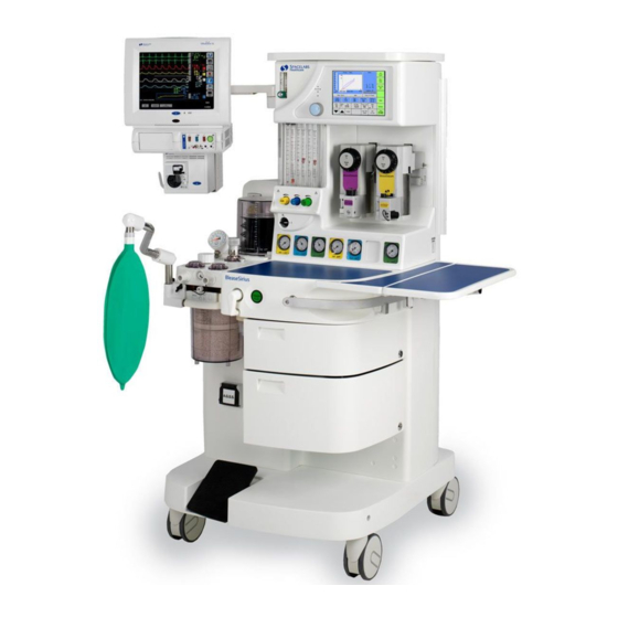
Spacelabs BleaseSirius Technical Manual (298 pages)
Anesthetic Machine With 700/900 Series Ventilators
Brand:
Spacelabs
| Category:
Medical Equipment
| Size: 13.33 MB
Table of Contents
Table of Contents
7
Chapter 1-Technical Description
19
Description
21
General
21
The Frame
21
Pneumatic Assembly
21
The Monitor Shelf
21
Figure 1 - Bleasesirius Anesthetic Machine
22
Specifi Cation
24
Machine Dimension
24
Work Surface Dimensions
24
Monitor Shelf Dimensions
24
Maximum Loading
24
Pneumatics
25
Gas-Specifi C Color Specifi Cations
25
Gas Supply Combinations
25
Common Gas Outlet
25
Technical/Performance Specifi Cation
26
Controls
26
Ventilator
26
Alarms / Indicators
26
Regulator Safety Valve Settings
26
Electrical
27
Figure 2 - Electrical Labeling
27
Supplies
28
Environmental
28
Chapter 2-Overview
29
Description of the Ventilator
31
Overview
31
Peep
31
Figure 3 - PEEP Diagram
31
Trigger
32
Support Pressure
32
Fresh Gas Compensation
32
Oxygen
32
Tidal Volume
32
Minute Volume
32
Expired Tidal Volume
32
BPM (Frequency Control)
32
I:E Ratio
33
Pressure Limit
33
Peak Pressure
33
Mean Pressure
33
Compliance
33
Volume Measurement
33
Oxygen Measurement
33
Pre-Use Test
34
Fresh Gas
34
Compliance
34
Compensation
36
Mode Dependant Features
37
Figure 4 - Ventilator Schematic
38
Figure 5 - Absorber Pneumatic Schematic
39
Figure 6 - Pneumatic Circuit
40
Principles of Operation
41
Chapter 3-Planned Maintenance
43
Planned Maintenance
45
Figure 7 - Bleasesirius Annual Planned Maintenance Kit
46
Figure 8 - Bleasesirius Four Year Planned Maintenance Kit PN 14000512
47
Routine Maintenance and Service Check
48
Fitting Planned Maintenance Kit PN 14000511
48
Bodoc Seals
48
Backbar Seals
48
Backbar Dzus Springs
48
Absorber Stop/'O' Ring
48
Pipeline Fitting and 'O' Ring
48
Figure 9 - Pipeline Fitting & 'O' Ring
49
AGSS Probe and Float for Spacelabs AGSS
50
PN 14200018, (if Fitted)
50
Figure 10 - AGSS
50
Bellows Base/Canister
51
Pop-Off Valve
51
Figure 11 - Pop-Off Valve
51
Figure 12 - Bellows Assembly
52
Absorber
53
Valve Covers
53
Manometer
53
Canister Seals
53
Fitting 4 Year Planned Maintenance Kit, PN 14000512
54
Ventilator Filter
54
Two Valve Version Only (on Units before Feb 2009)
54
Valve Block on Units after Feb 2009
54
Figure 13 - Pneumatic Module
54
Cylinder Regulator Pressure Relief Valve, PN 019-0831-00
55
Cleaning
56
Figure 14 - Primary Regulator
57
Chapter 4-System Checks
59
Overview
61
Tools and Test Equipment Required
61
Parts Required
62
Figure 15 - Bleasesirius Checkout Sheet (PN 073-0301-00 Rev. C)
64
Visual Inspection
65
Pipeline Leak Test
66
Figure 16 - Connect the Pipeline Test Shut-Off Valve
66
Figure 17 - N O Pipeline Gauge
67
Cylinder Leak Test
68
Regulator Output Test
68
Figure 18 - Connect Pressure Measuring Device
69
Figure 19 - Regulator Nut and Set Crew Locations
69
On/Off Switch Gas Cut off Test
70
Oxygen Supply Failure Test
70
High Pressure Outlet Test
71
Parts Required
71
Figure 20 - Test Hose Assembly
71
Hypoxic Guard and Flow Control Accuracy Tests
72
Figure 21 - Test Hose Connections
72
Figure 22 - Connect O
73
Backbar Tests
74
Pressure Build-Up Test
74
Figure 23 - Pressure Build-Up Test
74
T1 Backbar Test
75
Figure 24 - Fit 6 MM Plug
75
Figure 25 - Steps 5 and 8
75
T2 Backbar Test
76
Figure 26 - Step 4: Plug the CGO Taper
76
Figure 27 - Steps 6 and 8
76
Common Gas Outlet (CGO) Test
77
Oxygen Flush Test
77
Pressure Relief Valve Test
77
Figure 28 - O Flush Test
77
Figure 29 - Connect Pressure Measuring Device
77
Suction System Test
78
Figure 30 - Suction Gauge and Bowl
78
Absorber Tests
79
Expiratory Valve Leak Test
79
Figure 31 - Expiratory Valve Test Setup
79
Inspiratory Valve Leak Test
80
Figure 32 - Setup for Inspiratory Valve Test
80
APL Valve Check
81
Figure 33 - Steps 3 & 4 of the Inspiratory Valve Test
81
Figure 34 - Connect a Pressure Measuring Device
81
Figure 35 - Connect the Pressure Sampling Tee
82
Figure 36 - Step 5: Occlude the Bag Port
82
Ventilator Test
83
Figure 37 - Exhaust Port Location
83
Figure 38 - Step 11: Disconnect Patient Hose
84
Figure 39 - Connect a Flow Measuring Device
84
Figure 40A - Change the Flow Sensor Settings
85
Figure 40B - Pedi Sensor Placement Setting
85
Figure 41 - Connect a Pressure Measuring Device
86
Vaporizer Output Concentration Check
89
Figure 42 - Step 5: Connect a Reusable Tube
89
Figure 43 - Connect a Pressure Sample Tee
90
Figure 44 - Gas Analyzer Connection
90
Electrical Safety Test
91
Complete the Bleasesirius Checkout Sheet
92
Chapter 5-Detailed Repair Procedures
93
Removal/Replacement Instructions
95
Removal of Outer Cases (on Units up to Jan 2009)
95
Figure 45 - Removal of Top Surface
95
Figure 46 - Removal of Screw as Shown
96
Figure 47 - Removal of Top Screws as Shown
96
Removal of Outer Cases (on Units after Jan 2009)
97
Figure 48 - Removal of Front Cover
97
Figure 49 - Front Cover Fixing Screws (on Units after Jan 2009)
97
Figure 50 - Front of Machine with Front Cover Removed (Close-Up)
99
Figure 51 - Rear of Machine
100
Figure 52 - Rear Panels
101
Figure 53 - Removal of Large Rear Panel
102
Mechanical Hypoxic Guard Block
103
Introduction
103
Flow Meter Removal
104
Figure 54 - Flow Meter Removal
104
Figure 55 - BL1 Connector Location
105
Figure 56 - Flow Tube Removal
106
Replacement of Hypoxic Guard Block (FR135025)
107
Figure 57 - Removal of Screws on Flow Meter Assembly
107
Figure 58 - Rear of Flow Meter Assembly
107
Calibration of Hypoxic Guard System
108
Figure 59 - Hypoxic Guard Fi Xing Screws
108
Calibration Procedure
109
Setting Oxygen Basal Flow
110
Nitrous Oxide and Air Flow Valve Leak Test
111
Figure 60 - Assembled Hypoxic Guard Unit
111
Figure 61 - Exploded View of Hypoxic Guard Components
112
Figure 62 - Flow Block Showing Flow Tube Filters and Tube Lower Inserts
113
Figure 63 - View of Assembled Hypoxic Guard from below
114
Mechanical Hypoxic Guard Regulators, Adjustment and Output Check
115
Figure 64 - Test Points
116
Figure 65 - Pre Feb 2009 Regulator Adjustment
117
Hypoxic Regulator Replacement (for Units Manufactured before Feb 2009)
117
Figure 66 - Rear Panel Screw Locations (8)
118
Figure 67 - Secondary Gas Test Point Locations
118
Figure 68 - Secondary Gas Regulator Locations
119
Figure 69 - Adjust the Regulator Set Screw
120
Cylinder Regulator Pressure Relief Valve Replacement
122
Figure 70 - Primary Regulator Assembly
122
Figure 71 - Cylinder Regulator Locations
123
Figure 72 - Location of Bonnet
123
Replace the Cylinder Regulators
123
Figure 73 - Diaphragm and Actuator Assemblies
124
Figure 74 - Valve Cartridge and Relief Valve
124
Figure 75 - Regulator Service Kit
125
Figure 76 - Valve Cartridge and Seal Ring
125
Figure 77 - Assemble the Spring, Spring Rest and Bonnet
126
Figure 78 - Slip Ring Location
126
Figure 79 - Diaphragm Assembly
126
Figure 80 - Fit the Actuator Assembly
127
Figure 81 - Attach the Bonnet to the Regulator
127
Figure 82 - Fit the Relief Valve to the Regulator
128
Backbar Valve Replacement
129
Figure 83 - Location of Valve Retaining Screws
129
Figure 84- Backbar Valve
129
Common Gas Outlet (CGO) Removal/Replacement (up to Feb 2009)
130
Figure 85 - CGO Block (up to Feb 2009)
130
Alarm Block Removal/Replacement
131
On Units Manufactured before Feb 2009
131
Figure 86 - Alarm Block Removal (up to Feb 2009)
131
On Units Manufactured after Feb 2009Feb 2009 Onwards)
132
Figure 87 - Alarm Block Removal (Feb 2009 Onwards)
132
Oxygen Flush & Common Gas Outlet Safety Valve Adjustment
133
(Up to Feb 2009)
133
Figure 88 - CGO Adjustment (up to Feb 2009)
133
Oxygen Flush Adjustment on Units Sold before July 2010 (Units Sold after July 2010 Are Not Adjustable.)
134
Figure 89 - Valve Adjuster and Disc Removed (up to Feb 2009)
134
Common Gas Outlet (CGO) Removal/ Replacement (from Feb 2009 Onward)
135
Figure 90 - CGO Block (Feb 2009 Onwards)
135
Figure 91 - Location of (4) Suction Plate Screws
136
Figure 92 - Location of (3) ACGO Assembly Screws
136
Figure 93 - Location of 6 MM Tubing
136
Figure 94 - Location of 8 MM Tubing
137
Figure 95 - Location of 6 MM Tubing
137
Figure 96 - Location of 8 MM Stem
137
Figure 97 - Location of Microswitch
138
Figure 98 - ACGO Tubing Orientation
138
Figure 99 - ACGO Switch Set to Absorber
139
Figure 100 - A.C.G.O Ventilator Screen Display
139
ON/OFF Switch (PN FR142028)
140
Figure 101 - Microswitch Components
140
Figure 102 - Ventilator Wire Orientation
141
Figure 103 - NC Valves (PN 214-1089-00)
142
Figure 104 - 4-6 MM Increaser (PN 54200184) and
142
Figure 105 - 5 MM Tubing (1) and 6 MM Tubing (2)
143
Figure 106 - Tubing Diagram
144
Figure 107 - Tighten Two Screws
145
Test Procedure for Microswitches
145
Absorber
146
General
146
Absorber Interface Manifold Assembly
150
Figure 108 - Absorber Interface Manifold Assembly
150
Absorber Alignment
151
Standby / Run
151
Figure 109 - 'P' Clip
151
Absorber Docking
152
Figure 110- Absorber Prongs
152
Figure 111 - Micro Switch
152
Setting Ball Catch
153
Figure 112 - Setting Ball Catch
153
Figure 113 - Lock Screw Insertion
154
Internal Absorber
155
Figure 114 - Absorber Molding 01
155
Figure 115 - Absorber Molding 02
155
Figure 116 - Absorber Molding 03
156
Figure 117 - Absorber Molding 04
156
Figure 118 - Internal View of Absorber Moldings
157
Figure 119 -Valve Arc
157
Bellows Interface Gasket
158
Figure 120 - Bellows Interface Gasket Fixing Screws
158
Figure 121 - Gasket Removed
158
Servicing the Bag Arm
159
Drawer Removal/Replacement
164
Figure 122 - Drawer Mechanism
164
Figure 123 - Location of Drawer Mechanism and Removal
165
Figure 124 - Drawer Mechanism
166
Figure 125 - Drawer Re-Assembly
166
Braking System Maintenance
167
Figure 126 - Pedal Screw Location
167
Figure 127 - Hex Bar
167
Figure 128 - Hex Bar Removal
167
Castors Maintenance
168
Figure 129 - Location of Caster Retaining Screw
168
Figure 130 - Caster Removal
168
Suction Controller Removal/Replacement
169
Figure 131 - Suction Controller Removal / Replacement
169
Figure 132 - Suction Controller in Place
170
Figure 133 - Electrical Fuses
171
Ventilator
172
Inspiratory Block Assembly
172
Figure 134 - Ventilator Case Top
172
Ventilator Internal System
173
Replacement of Major Components
173
Figure 135 - Inside the Ventilator (Top View)
173
Removal of Inspiratory Block (FR137025)
174
Figure 136 - View of Removed Inspiratory Block
176
Removal of BAV Controller (FR101027)
177
Figure 137 - View of BAV Controller
177
Removal of BAV Power Supply (FR136029)
178
Figure 138
178
Figure 139
178
Removal of Front Panel (FR101026)
179
Figure 140 - Ventilator Control Knob
179
Figure 141 - Front Panel Retaining Screws
180
Figure 142 - Front Panel (Rear View)
180
Removal of the Screen (FR812025)
181
Removal of Switch Mode Power Supply (FR136025)
182
Removal of Flow Control Valves (up to March 2009)
183
Removal of Gas Inlet Module (FR 140026) (up to March 2009)
184
Figure 143 - Gas Inlet Module
184
Replacement of Battery (80300025)
185
Figure 144 - Replace the Battery
185
Exchanging of Fuses (EF533789)
186
Figure 145 - Replace the Fuses
186
Major Component Installation
187
Set up Options
188
Fresh Gas Calibration (2)
189
Absorber Fi Tted (3)
189
Sigh (4)
189
Gas Exhaust (5)
190
Enable Pre-Use Test (6)
190
Touch Calibration (7)
190
Ventilator Service Mode Passwords
191
Passwords Used in the Service Mode
191
Test Procedure
199
Reprogramming
200
Software Upgrade Procedure
200
To Use Ventflash
201
Figure 146 - Ventflash Screen
201
Figure 147 - Ventflash Sync Screen
201
To Upgrade the Language File
202
Figure 148 - Ventflash Check Language Screen
202
To Upgrade the Ventilator Model
203
Chapter 6-EFM Option
205
Figure 149 - EFM Components
207
Figure 150 - System Information
209
Figure 151 - EFM Hypoxic Guard Block Assembly
210
Figure 152 - EFM-Machine Retaining Screws
211
Figure 153 - Ribbon Cable, Power Connector and Light Pipe Locations
211
Figure 154 - Flow Tube Locations
212
Figure 155 - Flow Sensor Screw Locations
212
Figure 156 - Banjo Fitting
212
Figure 157 - Hypoxic Guard Retaining Screws
213
Figure 158 - Screen Retaining Screws
214
Figure 159 - Screen-Circuit Board Connectors (3)
215
Figure 160 - Circuit Board Screws (6)
217
Figure 161 - Flow Sensor
218
Figure 162 - Software Update Panel
220
Figure 164 - Exit Panel
222
Figure 163 - Confi Guration Panel
222
Figure 165 - Diagnostics Panel
223
Figure 166 - Detect Sensors Display
224
Figure 167 - Touch-Screen Panel
226
Figure 168 - Exit Panel
227
Schematic 1 - Title Block
228
Schematic 2 - SOM Interface
229
Schematic 3 - Power
230
Schematic 4 - I2C Sensors
231
Schematic 5 - Sensors
232
Schematic 6 - LCD Digital
233
Schematic 7 - LCD/LCD Power
234
Schematic 8 - SD Card
235
Schematic 9 - Development Circuits
236
Error Codes
237
Chapter 7 Error Codes
237
Error Codes
239
Error Codes on the Blease700/900 Series Ventilators
239
Chapter 8-Spare Parts
241
Parts List
243
Chapter 9-Notices And Important Information
253
Product Improvement
255
Responsibilities of the User
255
Responsibilities of the Manufacturer
255
Disclaimer
256
Technology Disclaimer / Tamper Proof Seal
256
Note to Service Personnel
256
CE Mark
257
Trademarks and Acknowledgements
258
Hazard Notices
259
Bleasesirius Warnings
260
Electrostatic Sensitive Devices (ESD) Warnings and Cautions
262
Cautions
263
Ventilator Warnings
264
Hazard Information
265
Cautionary Notices
268
Vaporizer Warnings
270
Absorber Warnings
271
Cautionary Notices
272
Chapter 10-Schematics
273
Schematic 10 - 10110326 Pressure Interface Board - Master
275
Schematic 11 - 10110326 Pressure Interface Board - Transducers
276
Schematic 12 - 10110326 Pressure Interface Board - Patient Flow
277
Schematic 13 - 10110326 Pressure Interface Board - Fresh Gas
278
Schematic 14 - 10110375 Blease LVDS Display Interface Sht. 1 of 4
279
Schematic 15 - 10110375 Blease LVDS Display Interface Sht. 2 of 4
280
Schematic 16 - 10110375 Blease LVDS Display Interface Sht. 3 of 4
281
Schematic 17 - 10110375 Blease LVDS Display Interface Sht. 4 of 4
282
Schematic 18 - 10110376SCH Power Supply Board
283
Schematic 19 - 10110377SCH Controller Board, CPU
284
Schematic 20 - 10110377SCH Controller Board, Alarms
285
Schematic 21 - 10110377SCH Controller Board, Connect
286
Schematic 22 - 10110377SCH Controller Board, Analogue
287
Schematic 23 - 10110377SCH Controller Board, I/O Circuits
288
Schematic 24 - 10110377SCH Controller Board, PWM
289
Schematic 25 - 10110377SCH Controller Board, Xilinx PWM and I/O
290
Schematic 26 - 13600381 Cable Assy Sirius Vent Interface Sht 1Of 2
291
Schematic 27 - 13600381 Cable Assy Sirius Vent Interface Sht 2Of 2
292
Schematic 28 - 13600379SCH Sirius Power Distribution 110VA
293
Schematic 29 - 13600379SCH Transformer Interconnections & Soft-Start PCB - 110V
294
Schematic 30 - 13600379SCH Transformer Interconnections & Soft-Start PCB - 230V
295
Advertisement
Advertisement
Related Products
Spacelabs Ultraview 91341
Spacelabs Ultraview 91343
Spacelabs Ultraview 91347
Spacelabs Categories
Blood Pressure Monitor
Measuring Instruments
Medical Equipment
Monitor
More Spacelabs Manuals
Login
Sign In
OR
Sign in with Facebook
Sign in with Google
Upload manual
Upload from disk
Upload from URL