Sign In
Upload
Manuals
Brands
Michell Instruments Manuals
Measuring Instruments
QMA601
Michell Instruments QMA601 Manuals
Manuals and User Guides for Michell Instruments QMA601. We have
3
Michell Instruments QMA601 manuals available for free PDF download: User Manual, Replacement Manual
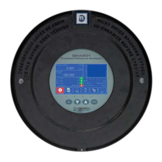
Michell Instruments QMA601 User Manual (110 pages)
Process Moisture Analyzer
Brand:
Michell Instruments
| Category:
Measuring Instruments
| Size: 5 MB
Table of Contents
Table of Contents
4
Safety
8
Warnings
8
Electrical Safety
8
Pressure Safety
8
Hazardous Materials (WEEE, Rohs3 & REACH)
8
Calibration (Factory Validation)
9
Repair and Maintenance
9
Abbreviations
10
1 Introduction
11
General
11
Theory of Operation
12
Sample Gas Path
13
Figure 1 Measurement System
13
2 Installation
14
Analyzer Storage Instructions
14
Unpacking the Analyzer
15
Lifting and Handling
15
Mounting the Analyzer
16
Figure 2 Mounting Dimensions
16
Hazardous Area/Location Safety
17
Electrical Safety
18
Equipment Ratings and Installation Details
18
Figure 3 Earth Bolt and Nut Washer Assembly
19
Power Connection
20
Figure 4 24 V DC & 240 V AC Power Unit Connectors
20
Other Electrical Connections
21
Figure 5 Other Electrical Connections
21
Pressure Safety
22
Figure 6 RJ45 to Screw Terminal Adapter Connections
22
Gas Sample Connections
23
3 Operation
25
General Operational Information
25
First Time Operation
26
Analyzer Set-Up
27
Figure 7 Typical Display
27
User Interface
28
Interface Controls
28
Up/Down Arrow' Keys
28
Figure 8 User Interface
28
Figure 9 Up/Down Arrow Keys
28
ENTER' Key
29
ESC' Key
29
Figure 10 'ENTER' Key
29
Figure 11 'ESC' Key
29
Pop up Keypad
30
Figure 12 Pop up Keypad
30
Table 1 Pop up Keypad
30
Menu Structure
31
Figure 13 Menu Structure
31
Description of Measured Parameters
32
Main Screen
32
Figure 14 Main Screen
32
Table 2 Main Screen Parameters
33
Large Display Mode
34
Figure 15 Large Parameter Display Mode
34
Table 3 Large Parameter Display Mode
34
Figure 16 Full Screen Graph
35
Main Screen Sub Menus
36
Warning Screen
36
Figure 17 Warning Screen
36
Logging Screen
37
Figure 18 Logging Screen
37
Table 4 Warning Screen
37
Table 5 Logging Screen
37
Alarm Screen
38
Figure 19 Alarm Screen
38
Table 6 Alarm Screen Parameters
38
Field Calibration Screen
39
Figure 20 Calibration Screen
39
Table 7 Calibration Screen Parameters
40
Figure 21 Field Calibration Screen 2
41
Figure 22 Field Calibration Screen 3
41
Figure 23 Field Calibration Screen 4
42
Figure 24 Field Calibration Screen 5
42
Monitor Screen
43
Figure 25 Monitor Screen
43
Table 8 Monitor Screen Parameters
43
Settings Menu
44
Measurement Screen
44
Figure 26 Settings Menu Screen
44
Figure 27 Measurement Screen
45
Figure 29 Measurement Screen
45
Table 9 Measurement Screen
45
Figure 28 Carrier Gas Screen
46
Figure 30 External Options
48
Figure 31 Fixed Options
48
Figure 32 Atmos. Option
48
Outputs Screen
49
Figure 33 User Gas Setup Screen
49
Figure 34 Outputs Screen
50
Table 10 Outputs Screen Parameters
50
HMI Screen
51
Figure 35 HMI Screen
51
Table 11 HMI Setup Screen Parameters
52
Real Time Clock Screen
53
Figure 36 Real Time Clock Screen
53
Table 12 Real Time Clock Screen Parameters
53
Software Communications Screen
54
Ethernet Screen
54
Figure 37 Software Communications Screen
54
Figure 38 Ethernet Screen
54
Table 13 Software Communications Screen Parameters
54
Field Calibration History
55
About Screen
55
Figure 39 Calibration History Screen
55
Table 15 Calibration History Screen
55
Table 14 Ethernet Screen Parameters
55
Sampling Guidelines
56
Figure 40 about Screen
56
Measurement Cycle
59
Figure 41 Measurement Cycle (Reference Phase) - Dried Sample Flow
59
Figure 42 Measurement Cycle (Sample Phase) Calibration Flow
60
Calibration Cycle
61
Figure 43 Calibration Cycle (Reference Phase) - Dried Sample Flow
61
Figure 44 Calibration Phase - Sample Flow
62
4 Maintenance
64
Safety
65
Removal and Replacement of the Power Supply Fuse
65
Replacing the Optional Contamination Trap
65
Removal and Replacement of the Desiccant Column
66
5 Calibration
68
Traceability
68
6 Shipping
69
Preparation for Shipping and Packing if Not Supplied as a Sample System
69
7 Application Software Overview
70
System Requirements
70
System Connection
70
Getting Started
71
Connection Method (Serial Connection (RS485 or TCP)
72
7.3.1.1 RS485 Connection
72
Modbus TCP Connection (Ethernet)
72
Main Window
73
Using the Chart
74
Table 16 Using the Chart
74
Chart Options Window
75
Table 17 Chart Options
75
Data Logging
76
Configuring Logging Start Time
76
Configuring Logging Stop Time
77
Starting the Log
77
Viewing a Log
77
Parameters / Field Calibration
77
Field Calibration
78
Appendix A Technical Specification
80
Appendix B Hazardous Area Certification
83
Product Standards
83
Product Certification
83
Global Certificates/Approvals
83
Special Conditions of Use
84
Maintenance and Installation
84
Appendix C Modbus Holding Register Map
86
Table 18 Modbus Register Map
92
Set Points and Ranges
102
Gases for Gas Correction Values
103
Appendix D Quality, Recycling, Compliance & Warranty Information
105
Appendix E Return Document & Decontamination Declaration
107
Appendix F Calculating Conversion Factors for Gas Mixes
109
Advertisement
Michell Instruments QMA601 User Manual (112 pages)
Process Moisture Analyzer
Brand:
Michell Instruments
| Category:
Measuring Instruments
| Size: 2 MB
Table of Contents
Table of Contents
4
Safety
8
Warnings
8
Electrical Safety
8
Pressure Safety
8
Hazardous Materials (WEEE, Rohs2 & REACH)
8
Calibration (Factory Validation)
9
Repair and Maintenance
9
Abbreviations
10
1 Introduction
11
General
11
Theory of Operation
12
Sample Gas Path
13
2 Installation
14
Analyzer Storage Instructions
14
Unpacking the Analyzer
15
Lifting and Handling
15
Mounting the Analyzer
16
Hazardous Area/Location Safety
17
Electrical Safety
18
Equipment Ratings and Installation Details
18
Figure
19
Power Connection
20
Other Electrical Connections
21
Figure 5 Other Electrical Connections
21
Pressure Safety
22
Gas Sample Connections
23
3 Operation
25
General Operational Information
25
First Time Operation
26
Analyzer Set-Up
27
Figure 7 Typical Display
27
User Interface
28
Interface Controls
28
Up/Down Arrow' Keys
28
Figure 8 User Interface
28
Figure 9 Up/Down Arrow Keys
28
ENTER' Key
29
ESC' Key
29
Pop up Keypad
30
Figure 12 Pop up Keypad
30
Table 1 Pop up Keypad
30
Menu Structure
31
Description of Measured Parameters
32
Main Screen
32
Table 2 Main Screen Parameters
33
Large Display Mode
34
Table 3 Large Parameter Display Mode
34
Figure
34
Figure 16 Full Screen Graph
35
Main Screen Sub Menus
36
Warning Screen
36
Logging Screen
37
Figure 18 Logging Screen
37
Table 4 Warning Screen
37
Table 5 Logging Screen
37
Alarm Screen
38
Table 6 Alarm Screen Parameters
38
Field Calibration Screen
39
Table 7 Calibration Screen Parameters
40
Figure
42
Monitor Screen
43
Figure 25 Monitor Screen
43
Table 8 Monitor Screen Parameters
43
Settings Menu
44
Measurement Screen
44
Figure 27 Measurement Screen
45
Figure 29 Measurement Screen
45
Table 9 Measurement Screen
45
Outputs Screen
49
Figure 34 Outputs Screen
50
Table 10 Outputs Screen Parameters
50
HMI Screen
51
Figure
51
Table 11 HMI Setup Screen Parameters
52
Real Time Clock Screen
53
Table 12 Real Time Clock Screen Parameters
53
Software Communications Screen
54
Ethernet Screen
54
Figure 37 Software Communications Screen
54
Table 13 Software Communications Screen Parameters
54
Field Calibration History
55
About Screen
55
Table 15 Calibration History Screen
55
Table 14 Ethernet Screen Parameters
55
Sampling Guidelines
56
Measurement Cycle
59
Calibration Cycle
61
4 Maintenance
63
Safety
65
Removal and Replacement of the Power Supply Fuse
65
Replacing the Optional Contamination Trap
65
Removal and Replacement of the Desiccant Column
66
5 Calibration
68
Traceability
68
Figure 45 Typical QMA601 Calibration Certificate
69
6 Shipping
70
Preparation for Shipping and Packing if Not Supplied as a Sample System
70
7 Application Software Overview
71
System Requirements
71
System Connection
71
Getting Started
72
Connection Method (Serial Connection (RS485 or TCP)
73
7.3.1.1 RS485 Connection
73
Modbus TCP Connection (Ethernet)
73
Main Window
74
Using the Chart
75
Table 16 Using the Chart
75
Chart Options Window
76
Table 17 Chart Options
76
Data Logging
77
Configuring Logging Start Time
77
Configuring Logging Stop Time
78
Starting the Log
78
Viewing a Log
78
Parameters / Field Calibration
78
Field Calibration
79
Appendix A Technical Specifi Cation
81
Appendix A Technical Specifi Cation
83
Appendix B Hazardous Area Certifi Cation
83
Product Standards
84
Product Certifi Cation
84
Global Certifi Cates/Approvals
84
Special Conditions of Use
84
Maintenance and Installation
85
Appendix B Hazardous Area Certifi Cation
87
Appendix C Modbus Holding Register Map
87
Table 18 Modbus Register Map
93
Set Points and Ranges
103
Gases for Gas Correction Values
104
Appendix D Quality, Recycling, Compliance & Warranty Information
105
Appendix E Return Document & Decontamination Declaration
107
Appendix F Calculating Conversion Factors for Gas Mixes
109
Michell Instruments QMA601 Replacement Manual (56 pages)
Brand:
Michell Instruments
| Category:
Measuring Instruments
| Size: 4 MB
Table of Contents
Table of Contents
3
Symbols
5
Description
6
Tools/Consumables Required
7
Oven Assembly Replacement
7
Moisture Generator Replacement
8
Crystal Sensor Replacement
9
O-Ring Replacement
10
HMI Replacement
11
Control PCB Fuse Replacement
12
Qma601
13
Removal of the QMA601 Lid
13
Removal of the QMA601 Oven Lid
14
Qma601 Oven Replacement
15
Removal of the QMA601 Oven
15
Replacement of the QMA601 Oven
16
Replacement of the QMA601 Lid and Pressure Testing
16
Qma601 Moisture Generator Replacement
17
Removal of the QMA601 Moisture Generator
17
Replacement of the QMA601 Moisture Generator
18
Replacement of the QMA601 Lid and Pressure Testing
19
Qma601 Crystal Sensor Replacement
20
Removal of the QMA601 Sensor Block and Oscillator PCB
20
Replacement of the QMA601 Sensor Block
24
Replacement of the QMA601 Lid and Pressure Testing
24
Qma601 O-Ring Replacement
25
Removal of the QMA601 Lid and O-Ring
25
Replacement of the O-Ring and QMA601 Lid
25
Qma601 Hmi Replacement
26
Removal of the QMA601 Lid and HMI Assembly
26
Replacement of the QMA601 HMI Assembly
26
Replacement of the QMA601 Lid
26
Qma601 Control Pcb & Fuse Replacement
27
Removal of the QMA601 Lid, Control PCB and Fuse
27
Replacement of the Fuse and QMA601 Control PCB
28
Replacement of the QMA601 Lid and Pressure Testing
28
Qma601 Lid Replacement
29
Replacement of the QMA601 Oven Lid
29
Replacement of the QMA601 Lid
29
Qma601 Pressure Testing
31
Qma401
32
Removal of the QMA401 Cover
32
Removal of the QMA401 Oven Lid
33
Qma401 Oven Replacement
34
Removal of the QMA401 Oven
34
Replacement of the QMA401 Oven
35
Replacement of the QMA401 Lid and Pressure Testing
35
Qma401 Moisture Generator Replacement
36
Removal of the QMA401 Moisture Generator
36
Replacement of the QMA401 Moisture Generator
37
Replacement of the QMA401 Lid and Pressure Testing
38
Qma401 Crystal Sensor Replacement
39
Removal of the QMA401 Sensor Block and Oscillator PCB
39
Replacement of the QMA401 Sensor Block
43
Replacement of the QMA401 Lid and Pressure Testing
43
Qma401 Fuse Replacement
44
Removal of the Fuse in the QMA401 Control PCB
44
Replacement of the QMA401 Fuse
44
Replacement of the QMA401 Lid and Pressure Testing
44
Qma401 Oven Lid and Cover Replacement
45
Replacement of the QMA401 Oven Lid
45
Replacement of the QMA401 Cover
45
Qma401 Pressure Testing
46
Resetting Moisture Generator / Dryer Remaining Lifetime
47
Appendix A Environmental Responsibility
48
Appendix B Swagelok Fitting Instructions
49
Appendix C F0121 Decontamination Certificate
50
Appendix D F0131 Hazardous Area Customer Service Declaration
51
Appendix E Field Performance Verification of QMA401/601
52
Advertisement
Advertisement
Related Products
Michell Instruments QMA401
Michell Instruments QMA Series
Michell Instruments QMA601-LR
Michell Instruments Cermet II
Michell Instruments Condumax II
Michell Instruments Easidew DryCheck
Michell Instruments Easidew Online
Michell Instruments Easidew Portable HP
Michell Instruments Easidew Portable Standard
Michell Instruments ES20
Michell Instruments Categories
Measuring Instruments
Transmitter
Analytical Instruments
Accessories
Test Equipment
More Michell Instruments Manuals
Login
Sign In
OR
Sign in with Facebook
Sign in with Google
Upload manual
Upload from disk
Upload from URL