Table of Contents
Advertisement
Quick Links
Advertisement
Table of Contents

Related Manuals for Drazice AQUA HP 250 I


Summary of Contents for Drazice AQUA HP 250 I
- Page 1 OPERATING AND INSTALLATION MANUAL WATER HEATER WITH HEAT PUMP AQUA HP Družstevní závody Dražice-strojírna s.r.o. (Works Cooperative - Dražice - Machine Plant, Ltd.) Dražice 69, 294 71 Benátky nad Jizerou tel.: +420 / 326 370 911 fax: +420 / 326 370 980 e-mail: export@dzd.cz...
-
Page 2: Table Of Contents
CONTENTS INTRODUCTION ............................. 5 INFORMATION PRIOR TO THE INSTALLATION ................5 SAFETY INFORMATION ....................... 5 SPECIFICATIONS ............................. 7 COMPONENTS ..........................7 HEAT PUMP PRINCIPLE ....................... 8 TECHNICAL PARAMETERS ......................9 TRANSPORT ............................10 INSTALLATION ............................. 10 SAFETY AND CONTROL DEVICE ....................10 4.1.1 LOW-PRESSURE/HIGH-PRESSURE FUSE ................ - Page 3 OPERATING MODES ........................22 5.5.1 ECO MODE ........................22 5.5.2 AUTO MODE ........................23 5.5.3 BOOST MODE........................23 5.5.4 TCC MODE ......................... 23 5.5.5 LAT MODE ......................... 24 ADDITIONAL FUNCTIONS ......................24 5.6.1 DISINFECTION MODE ......................24 5.6.2 HOLIDAY MODE ........................ 24 MENU ............................
- Page 4 CAREFULLY READ THIS MANUAL BEFORE INSTALLING THE WATER HEATER! Dear Customer, The Works Cooperative of Dražice - Machine Plant, Ltd., would like to thank you for your decision to use a product of our brand. The product is not intended to be controlled by a) people (including children) with reduced physical, sensual or mental capacities, or b) people with insufficient knowledge and experiences unless supervised by responsible person, or unless properly instructed by such responsible person.
-
Page 5: Introduction
INTRODUCTION Water heater with an AQUA HP air-water heat pump certainly fulfils all your expectations, and will comfortably serve you and achieve maximum energy savings for many years. The manufacturer devotes a lot of time, energy and financial resources to the development of innovations that will promote energy savings achieved by using the product. - Page 6 During installation: • The installation of the water heater with heat pump must be performed by a qualified installer who has been properly trained and qualified to this activity. • The appliance must not be installed in locations where there is a risk of damage from impact, shock or explosion.
-
Page 7: Specifications
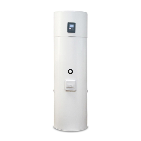
SPECIFICATIONS 2.1 COMPONENTS AQUA HP 250 I/IX - 7 -... -
Page 8: Heat Pump Principle
The cooling circuit located in the upper part is responsible for the transfer of heat from the ambient air into the water. 2.2 HEAT PUMP PRINCIPLE Expansion Evaporator Compresor valve Ambient air exhaust (exhaust duct) Capacitor HOT WATER RECEPTACLE - 8 -... -
Page 9: Technical Parameters
1. The coolant R134a is compressed in a highly efficient compressor that increases its pressure and temperature. 2. In a capacitor that is not in direct contact with water, the thermal energy contained in the coolant is transferred to the water in the hot water storage tank. 3. -
Page 10: Transport
Temperature of heating water (90/80 °C); hot water temperature (10/60 °C) Temperature of heating water (70/60 °C); hot water temperature (10/60 °C) A20/W10-54, according to EN16147 and applicable regulation No. 812/2013 TRANSPORT The appliance must be transported to the installation site in the original packaging and must be transferred in an upright position. -
Page 11: Temperature Sensor
4.1.3 Temperature sensor Temperature sensor measures the water temperature in the hot water tank to control the entire system. 4.1.4 Corrosion protection In addition, the top part shell of the hot water heater is corrosion resistant (it is made of stainless steel) and the hot water tank is enamelled and also contains magnesium anode which needs to be checked regularly, as recommended by the installer or service technician. -
Page 12: Location
4.2 LOCATION When placing the appliance to the installation site, keep in mind possible future service calls. To avoid having to leave too much space behind the tank, the magnesium anode is disposed on the front side of the hot water storage tank. -
Page 13: Installing Air Intake/Exhaust
4.3 INSTALLING AIR INTAKE/EXHAUST Since AQUA HP absorbs heat during operation, it is good to route cooled air (intake/exhaust) to unheated spaces. The appliance will cool the room in which it is located and if it is installed in heated rooms, cooled air should be routed to other rooms or outside. 4.3.1 Installation without air piping The AQUA HP appliance should be installed in a location that is not too heated and can be used for dehumidification and cooling these areas (e.g. -
Page 14: Installation With Air Piping
4.3.2 Installation with air piping If you use piping for airflow into spaces that do not require heating, you can: Use the outside air Using outdoor air, the unit can be placed either in heated or unheated room. Use air from an adjacent room The unit can also be placed in a heated room, but airflow should be directed to an unheated room. - Page 15 Use air from an adjacent room and outside air To supply air to the appliance, branched pipe can be used. In summer, you can use hot air from the outside and in winter you can use the air from the unheated area. UNHEATED AREA HEATED OR UNHEATED Min 50 m...
-
Page 16: Plumbing Fixture
4.4 PLUMBING FIXTURE EXPLANATORY NOTES Shutoff valve Pressure control valve (3 bar/0.3 MPa) Return valve Safety valve (6 bar/0.6 MPa) Sink drain Expansion receptacle Drain valve Circulation pump Thermostatic mixing valve Cold water connection Hot water outlet Circulation - 16 -... -
Page 17: Condensate
Safety valve has to be installed on the cold water inlet into the appliance. The safety device must comply with EN 1487: 002, maximum pressure of 6 bar (0.6 MPa). No closing armature may be mounted between the safety valve and the tank or check valve that could disable the safety valve. -
Page 18: Wiring Diagram
4.6 WIRING DIAGRAM Water heater with heat pump can be connected to power only when the tank is filled with water. Water heater with heat pump is supplied with a cable for connecting to a prepared grounded receptacle (1/N/PE ̴ 2 30 V/50 Hz). Wiring installation must conform to the standards applicable in the country or territory where the heater with heat pump is installed. -
Page 19: Control And Programming
CONTROL AND PROGRAMMING 5.1 CONTROL PANEL The Eco control panel of the appliance is simple and intuitive. It allows you to configure several operating parameters according to the operating mode selected by the user. It includes six control keys (ON/OFF / CANCEL MENU, ▲ COMP, E-HEATER and OK DISINFECT and OK / LOCK) that enable checking the operation of the appliance, monitoring the parameters and their change. -
Page 20: Display
5.3 DISPLAY 5.3.1 Display description 10:25 12/10/12 AUTO BOOST 45 ºC Er01 - S1 - 5.3.2 Symbols Symbol Description Appliance in ECO service mode AUTO Appliance in AUTO service mode BOOST Appliance in BOOST service mode Timer clock control ON Low ambient temperature protection ON Compressor ON Fan ON... -
Page 21: Symbols In The Appliance's Operation
5.3.3 Symbols in the appliance's operation Symbol Description (ON) Compressor ON (OK) Compressor ON and setting point achieved (TA) Electrical backup ON due to S1 < P08 and/or P07 < Temp. S3 (Auto mode) (TA) Electrical backup ON due to compressor ON to more than T05 (Auto mode) (MA) Electrical backup ON manually (ON) Electrical backup ON... -
Page 22: Operating Modes
Then you can start the device by following these instructions: 10:25 12/10/12 10:25 12/10/12 10:25 12/10/12 45 ºC 45 ºC Ver 0.M.X.X Controller when turned on Press the COMP key to The system is turned off (OFF) start the system Press the ON/OFF switch Note 1: LED on the display indicates the status of the appliance. -
Page 23: Auto Mode
AUTO 5.5.2 AUTO Mode In the AUTO mode, the unit works as a heat pump with the support of the heating element, and the operation of the heating element is optimised in order to maintain the COP of the appliance. The heating element starts whenever: •... -
Page 24: Lat Mode
5.5.5 LAT Mode LAT mode starts automatically at a low temperature of the input air in order to protect the compressor. When this mode is activated, the compressor shuts down and only electric heating activates. When the intake air temperature rises, the device returns to the previously selected mode. 5.6 ADDITIONAL FUNCTIONS 5.6.1 Disinfection Mode The AQUA HP controller includes a Disinfection (Anti-Legionella) function consisting of a water heating cycle... -
Page 25: Changing The Mode
5.8 CHANGING THE MODE ECO is set as the default mode for the operation of the device. If at any time the user wants to edit the operation mode they can proceed as follows: Unlock the keypad and hold the MENU key down for 3 seconds. Use the COMP ▲ and E-HEATER ▼ keys to browse the menu and select F03 to enter the submenu and select the operation mode. - Page 26 H01TCC - P01TCC parameter hysteresis 4°C P02TCC - required temperature, final el. heating 60°C H02PV - P02 parameter hysteresis 10°C P03 - defrost start -8°C P04 - defrost finish 16°C P05 - safe temperature 70°C P06 - Anti-Legionella disinfection temperature 65°C P07 - min evaporator temperature for final el.
-
Page 27: Error Messages Table
ERROR MESSAGES TABLE Symbol Description Trouble / Check Error - temperature Er01 – S1 • Damaged temperature sensor - Measure the internal resistance sensor 1 of the sensor which is about 10 KΩ at the temperature of 25 °C. Error - temperature •... -
Page 28: Temperature Sensor Parameters
TEMPERATURE SENSOR PARAMETERS Dependence of sensor's resistance on temperature Temperature (°C) - 28 -... -
Page 29: Troubleshooting
TROUBLESHOOTING Trouble Potential cause What to do Check the power supply. Power failure Check corresponding circuit breaker. Failure in the electronic board Check the integrity (intactness) of the Damaged or disconnected cable electronic circuit board. Low temperature programmed Adjust the temperature set point. as a set point 53 °C as default factory setting. -
Page 30: Maintenance Of The Appliance
Check the errors displayed on the Heat pump failure screen. Evaporator blocked Clean the evaporator. Fan blocked Check the fan status (dust, cable, ...). Check the condition of the hydraulic Low hot water flow Hydraulic circuit blocked circuit. Absence or incorrect size of the Installation or correct pressure in the expansion tank (unless the leak expansion receptacle. -
Page 31: General Maintenance
11.1 GENERAL MAINTENANCE The coolant in the device can be handled ONLY by a qualified refrigeration technician with valid authorisation. Over the lifetime of the appliance, user must perform general maintenance and control of the appliance depending on the place of installation: •... -
Page 32: Cleaning Of Pressure Control Valve
11.4 CLEANING OF PRESSURE CONTROL VALVE For regular cleaning of the pressure control valve, proceed as follows: • Shut off the water supply. • Turn anti-clockwise until the spring is under tension. • Remove the handle. • Remove the filter and clean it. 11.5 CONDENSATE DRAIN Remember within the routine maintenance and cleaning of the system to check the condensate drain system and the drip tray.
Need help?
Do you have a question about the AQUA HP 250 I and is the answer not in the manual?
Questions and answers