
Subscribe to Our Youtube Channel
Related Manuals for Pentair 3200NXT


Summary of Contents for Pentair 3200NXT
- Page 1 3200NXT Service Manual IMPORTANT: Fill in Pertinent Information on Page 3 for Future Reference...
-
Page 2: Table Of Contents
Table of Contents Job Specification Sheet ............................3 Timer Operation ..............................4 Timer Display Features ............................6 Timer Display - Screen Examples ......................... 7 Network/Communication Cables & Connections ....................8 Master Programming Mode Flow Chart......................... 9 Master Programming Guide ..........................13 User Mode Programming Flow Chart ........................ -
Page 3: Job Specification Sheet
Job Specification Sheet Please Circle and/or Fill in the Appropriate Data for Future Reference: Programming Mode: Feed Water Hardness: __________ Grains per Gallon or Degrees Regeneration Time: Delayed __________ AM/PM or __________ Immediate Regeneration Day Override: Off or Every __________ Days Time of Day: __________ Master Programming Mode:... -
Page 4: Timer Operation
Timer Operation Setting the Time of Day NOTE: Set Time of Day on the Lead Unit (#1) and the rest of the units in the system will populare with the Time of Day within 10 seconds. Press and hold the Up or Down button for 2 seconds. Press the Shift button to select the digit you want to modify. - Page 5 Timer Operation Timer Operation During Programming The timer enters the Program Mode in standby or service mode as long as it is not in regeneration. While in the Program Mode the timer continues to operate normally monitoring water usage. Timer programming is stored in memory permanently.
-
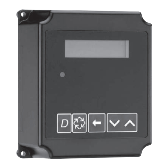
Page 6: Timer Display Features
Timer Display Features Valve State (SBY, SRV, INI, CHG, LCK) Valve Address System Flow Time Indicator Number of Day Display Screen Time of Day alternates with Error Screen Example: Valve #, Volume Remaining, Errors Volume Remaining Diagnostic Button View Flow Rate, Peak Flow Rate, Totalizer, Hours Between Last Two Regenerations, Hours Since Last Regeneration, Adjustable Volume Remaining, Valve Position, Send &... -
Page 7: Timer Display - Screen Examples
Timer Display - Screen Examples Example: In Service: System 4 Time Clock Example: In Service: System 4 Flow Meter Initiated System 4 Flow Meter Delayed Example: In Service: System 5 Flow Meter Initiated (Lead Unit) Example: In Service: System 5 Flow Meter Initiated (Lag Unit #3) Example: In Service: System 6 Flow Meter Initiated (Lead Unit) -
Page 8: Network/Communication Cables & Connections
3. Connect each unit together from one communication port to the next communication port. It does not matter which one goes to the next one. 3200NXT Circuit Board The number of network/communication cables needed for setup is one less than the total number of valves. -
Page 9: Master Programming Mode Flow Chart
Master Programming Mode Flow Chart NOTE: Depending on current option settings, some displays cannot be viewed or set. Entering Master Programming Mode: Press and hold the Shift and Up buttons for 5 seconds. Press the Extra Cycle button once per display until all displays are viewed and Normal Display is resumed.Option setting displays may be changed as required by pressing either the Up or Down button. - Page 10 Remote Signal Start Immediate (All System Types) Example: VALVE TYPE: 2750 (Default) 2750 Master Programming Mode Flow Chart Options: 2750 (Default) 2850 2900 3150 NOTE: Depending on current option settings, some displays cannot be viewed or set. 3900 Stager - Butterfly Stager - Notch Cam Example: REGENERANT FLOW:...
- Page 11 NOTE: Use the Shift button to move to the left. NOTE: This screen will only display on Example: the lead unit for System Types 6 & 7. FEED WATER 15 GPG (U.S. Format) (Default) HARDNESS: 15 GPG For all other System Types, it will display Master Programming Mode Flow Chart for all units.
- Page 12 Range: 00:00:00 to 18:00:00 NOTE: This screen will only display on the lead unit for System Types 6 & 7. Example: CHEMICAL PUMP: Master Programming Mode Flow Chart For all other System Types, it will display Chemical Pump is Disabled DISABLED for all units.
-
Page 13: Master Programming Guide
Master Programming Guide When the Master Programming Mode is entered, parameters can be set to make the timer(s) function as needed. NOTE: Depending on current option settings, some displays cannot be viewed or set. Entering Master Programming Mode: Press and hold the Shift and Up buttons for 5 seconds. Set the time of day display to 12:01 PM or 12:01HR (See the “Setting the Time of Day”... - Page 14 Master Programming Guide 3. System Size This program step is used to set up the number of valves (1, 2, 3, or 4) in the system. Use Up or Down buttons to adjust this value. Press the Extra Cycle button. 4.
- Page 15 Master Programming Guide 7. Remote Signal Start This program step selects the remote signal start. Hours, minutes, and seconds can be changed. When Remote Signal Start is active, the main screen will display. The options are either Off or set to the desired time. Use Up or Down buttons to adjust this value.
- Page 16 Master Programming Guide 10. Capacity Safety Factor This program step is used to adjust the capacity of the system. This is a percentage by which the unit’s capacity is reduced. Range: 0 – 50% (Default = 0%) Use the Shift button to select the digit you want to modify. Use Up or Down buttons to adjust this value.
- Page 17 Master Programming Guide 13. Regeneration Time This program step sets time of day for a delayed regeneration to occur, or regeneration day override. Default U.S.: 02:00 AM Default Metric: 02:00 HR Use the Shift button to select the digit you want to modify. Use Up or Down buttons to adjust this value.
- Page 18 Master Programming Guide 16. Timed Auxiliary Relay Output Window (Start & End Time Setting, If Auxiliary Relay is Enabled) This option setting consists of two displays. The first display sets the turn-on time of the output, referenced to the start of the first Regeneration Cycle. The second display sets the output turn-off time, referenced again to the start of first Regeneration Cycle.
- Page 19 Master Programming Guide 18. Fleck Flow Meter Size (Default to Valve Type) This program step sets the size of the Fleck flow meter. • 1.0” Paddle (2750 Default) • 1.5” Paddle (2850/2900 Default) • 2.0” Paddle (3150 Default) • 3.0” Paddle (3900 Default) •...
-
Page 20: User Mode Programming Flow Chart
User Mode Programming Flow Chart NOTES: User Mode is only displayed when a metered option is chosen under System Type. Depending on current option settings, some displays cannot be viewed or set. Entering User Mode: Hold the Up and Down buttons for 5 seconds. FEED WATER HARDNESS: REGENERATION DAY... -
Page 21: Diagnostic Mode Flow Chart
Diagnostic Mode Flow Chart Entering Diagnostic Mode: Push and release the “D” button. CURRENT FLOW Press the Extra Cycle button once per RATE: 0 gpm display until all displays are viewed and Normal Display is resumed. Push and release the “D” button at anytime PEAK FLOW RATE: during diagnostic mode and the timer will 0 gpm... -
Page 22: Diagnostic Programming Guide
Diagnostic Programming Guide When the Diagnostics Mode is entered, all available displays are viewed as needed. Depending on current option settings, some displays cannot be viewed. Overview Diagnostic Mode The current diagnostic will be displayed until Extra Cycle key is pressed. There is no time limit on each display. The timer will display individual valve information, not system information. - Page 23 Diagnostic Programming Guide Hours Between Last Two Regenerations The hours between the last two regenerations will be saved and displayed. Depress the Extra Cycle button. Hours Since Last Regeneration The hours since the last regeneration will be saved and displayed. Depress the Extra Cycle button.
- Page 24 Diagnostic Programming Guide Valve Address This diagnostic display is for 2 control valves or more in a system (a single valve will not display). Depress the Extra Cycle button. Software Version The electronic timer’s software program version number will be displayed. Depress the Extra Cycle button to exit.
- Page 25 Notes Page 25...
-
Page 26: 2750/2850/2900 Upper & 2900 Lower Powerhead Assy
2750/2850/2900 Upper & 2900 Lower Powerhead Assy 61501-3200NXT-2_Page2_REVA Page 26... - Page 27 2750/2850/2900 Upper & 2900 Lower Powerhead Assy Item No. Quantity Part No. Description 1 ....1 ....18697-15 ....backplate, hinged 2 ....1 ....60219-02 ....cover assy, environmental, black 3 ....1 ....60160-15 ....drive cam assy, stf, blue 4 ....1 ....10909 ......pin, link 5 ....
-
Page 28: 3150/3900 Upper & 3900 Lower Drive Powerhead Assy
3150/3900 Upper & 3900 Lower Drive Powerhead Assy 49 32 50 24 28 20 18 23 31 22 21 25 17 19 15 36 13 27 26 11 10 8 11 45 42 4 7 8 12 6 61501-3200NXT-3_Pg2_REVA Page 28... - Page 29 3150/3900 Upper & 3900 Lower Drive Powerhead Assy Item No. Quantity Part No. Description 1 ..... 1 .......19304-04 ....backplate, 3150/3900 2 ..... 1 .......15120 ......bracket, motor mtg, 3150/3900 3 ..... 1 .......40391 ......motor, drive, 24V, 50/60 hz, sp 4 ..... 8 .......11224 ......screw, hex hd, 5/16 - 18 x 5/8, ss 5 .....
-
Page 30: 2750/2850/3150 Input & Output Wiring
2750/2850/3150 Input & Output Wiring Page 30... -
Page 31: 2900/3900 Input & Output Wiring
2900/3900 Input & Output Wiring Page 31... -
Page 32: Troubleshooting
Troubleshooting Detected Errors NOTE: It can take up to 30 seconds for an error to be detected and displayed. All errors on each timer in the system must be displayed before the errors can be corrected. If a communication error is detected, an Error Screen will alternate with the main (time of day) screen every few seconds. - Page 33 Troubleshooting Cause Correction A. Any or all of two or more units programmed with the A. Program the units correctly in the Master same unit number (Matching Address Error) Programming Mode B. Flashing/blinking display B. Power outage has occurred C. Format Mismatch (Units have both U.S. and Metric C.
- Page 34 Notes Page 34...
- Page 35 Notes Page 35...
- Page 36 P/N 42599 Rev. C 4/09...
Need help?
Do you have a question about the 3200NXT and is the answer not in the manual?
Questions and answers