
Related Manuals for Pentair 962 Series


Summary of Contents for Pentair 962 Series
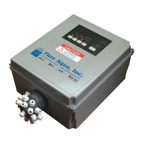
- Page 1 Series 962 Electronic Stager Control Operation Manual TIME OF DAY TIME OF REGEN HARDNESS FLOW SERIES 962 CAPACITY REGEN TIME REMAINING REGEN...
-
Page 3: Table Of Contents
Table of Contents Declaration of Conformity ....3 Caution and Warning Symbols ... . 4 Series 962 Electronic Stager Controls . -
Page 4: Caution And Warning Symbols
Caution and Warning Symbols The following international symbols appear in this circuit breaker must be in close proximity to this manual to highlight caution and warning messages. equipment and in easy reach of the operator. It must be clearly marked to indicate that it is the disconnecting Cautions device for this equipment. - Page 5 Inputs Terminal Strip 1 (TB1) High Voltage TB1, Terminal #1: Line Voltage Input TB1, Terminal #4: Neutral Input TB1, Terminal #6: Input to Aux. Switch Common Optional Relay Inputs Relay Terminal #6: Relay Common Input Terminal Strip 2 (TB2) Low Voltage TB2, Terminal #11: Turbine Meter Ground Input TB2, Terminal #12: Turbine Meter Shield Input TB2, Terminal #13: Turbine Meter Signal Input...
-
Page 6: Series 962 Electronic Stager Controls
Series 962 Electronic Stager Controls Double Regeneration The Series 962 Electronic Stager Controls provide sophisticated, demand-based water conditioning by For single tank applications, the control automatically combining a microprocessor with a flow meter to calls for a second regeneration the following day if the electronically monitor the amount of water used. -
Page 7: Remote Regeneration
Remote Regeneration Flow Rate Display A set of input terminals with a programmable delay are In the normal operating mode the series 962 Stager provided as a standard feature of the 962 Stager that control will alternate between Capacity Remaining allows regeneration to be initiated from a remote (gallons or m ) and Flow Rate (gallons per minute or... -
Page 8: Level I Programming
Level I Programming Level III Programming Level I program values are identified by the legend on Press and hold the (←) and (↑) arrow buttons for 3 the faceplate of the control. A green LED is illuminated seconds to enter the Level III programming mode. The when a Level I "P”... -
Page 9: Viewing A Program Value
Viewing a Program Value NOTE: When using the Relay Output Option the lockout feature cannot be used. Programmed values may be viewed at any time. Program values may not be changed during a Flow Sensor Select Options regeneration. P19 is used to select the flow sensor type. Numbers 1 Level I - To locate and display a P value in Level I press and 2 are for the Autotrol 1 inch and 2 inch turbine type the (↑) or (↓) arrow button until the desired value is... -
Page 10: Immediate Regeneration Only Option
P15 = 2 or 3 Immediate Regeneration Override In addition to delayed regenerations automatic regenerations will occur at any time during the day if the capacity remaining reaches zero. Immediate Regeneration Only Option Automatic regenerations performed at the time of regeneration (P2) can be eliminated by setting the control for fixed reserve with immediate regeneration override (P15 = 3) and setting the reserve capacity... - Page 11 Press and hold the (↑) and (↓) arrow buttons to access Level II. Table 1 - Level I and II Parameters Parameter Minimum Units of Range of Values Default Notes Increments Measure Name Description Range depends on value (1-7) 1:00-12:59 selected for P13.
- Page 12 Table 2 Conversions To Convert Capacity Into Capacity in Multiply by kilograms (kg) kilograins (kgr) 15.43 kilograins (kgr) kilograms (kg) 0.0648 moles of CaCO kilograms (kg) 0.10 equivalents of CaCO kilograms (kg) 0.05 ← Press and hold the ( ) and (↑) arrow buttons to access Level III. Table 3 Level III History Data Location Range...
- Page 13 ← Press and hold the ( ) and (↓) arrow buttons to access Level IV. Table 4 Level IV Parameters Minimum Description of Parameter Range of Values Default Notes Increment Position 1 Cycle Time 0 min -255 min 1 min Stager Cycle (P17=6 or 9) Position 2 Cycle Time 0 min -255 min...
- Page 14 Table 6 Error Code Identification Error Code Description Data stored in NOVRAM has been corrupted and is incorrect Home switch (SW 2) closed when it should be open Home switch (SW 2) open when it should be closed One or more parameters are below the minimum value in Table I System capacity less than 10 gallons or 0.1 m (Capacity is set too low or Hardness is set too high)
-
Page 15: Parallel Operation
Parallel Operation The 962 Stager control can be used for twin and triple lock-out signal will prevent other controls from starting a tank applications, operating in a parallel mode. Parallel regeneration when the controls are connected as in systems can be implemented with up to three individual Figure 2. -
Page 16: Flow Sensor Connections
Flow Sensor Connections The 962 Stager control may be connected to a number of different flow sensing devices. Figure 3 shows the connections for the Autotrol turbine type flow sensor. Figure 4 shows the connections for the Signet flow sensor. Most of the flow sensors that are used will be wired similarly, though the wire colors may vary. -
Page 17: Remote Regeneration
Remote Regeneration A set of terminals with a programmable delay (P21) are provided as a standard feature of the 962 control, Figure 6. This feature allows for a regeneration to be initiated from a remote location. This feature can also be used to accommodate a differential pressure switch input or any dry contact closure from external equipment. - Page 18 Figure 10 E948/E951 Standard Wiring Design...
- Page 20 © 2009 Pentair Residential Filtration, LLC P/N 1076301 Rev. H FE09...
Need help?
Do you have a question about the 962 Series and is the answer not in the manual?
Questions and answers