Pentair 255 Operation Manual
Hide thumbs
Also See for 255:
- Installer manual (92 pages) ,
- Service manual (20 pages) ,
- User manual (37 pages)
Table of Contents
Advertisement
Advertisement
Table of Contents

Related Manuals for Pentair 255


Summary of Contents for Pentair 255
- Page 1 2 2 5 5 5 5 / / L L O O G G I I X X 7 7 4 4 0 0 - - 7 7 6 6 0 0 Operation Manual Start up and Maintenance Manuel d’utilisation Mise en marche et Maintenance Manual de Puesta en Marcha Puesta en marcha y Mantenimiento...
-
Page 2: Table Of Contents
SYNOPSIS Valve Features ..........2 LCD Display . -
Page 4: Valve Features
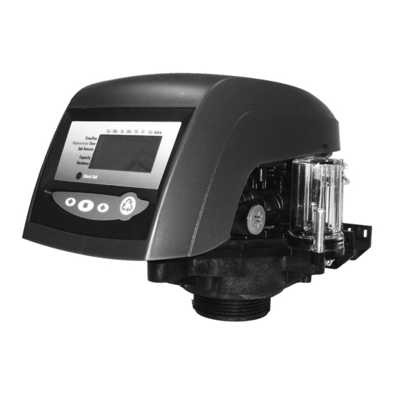
Complete Valve - Front view Control module One piece valve mount disc spring Optical sensor Refill Controller Injector and cap Manifold connection Aircheck Check ball Regenerant tank tube connection Complete Valve - Back view Valve discs Camshaft Motor Outlet Drain Inlet Backwash Locking bar... -
Page 5: Lcd Display
LCD Display LCD Display Manual regen Down button button button Button Chlorine generator outlet (EU and 742/762 versions only) AC adapter input Lockout connection (low voltage) (772 only) Secondary valve motor control (772 only) Sensor input 716 by turbine 760/762 Dry contact signal input 740/742... -
Page 6: Installation
Service or routine maintenance procedures may also require that the system is bypassed. Figure 1 and 2 show the three common bypass methods. Figure 1 256 By-pass for use with 255 valve body. Normal operation In by-pass Figure 2... -
Page 7: Drain Line Connection
Drain line connection NOTE : Standard commercial practices are expressed here. Local codes may require changes to the following suggestions. Check with local authorities before installing a system. 1. If the backwash flow rate exceeds 5 gpm (22.7 Lpm) or if the unit is located 20-40 feet (6.1-12.2 m) from drain, use 3/4-inch (1.9 cm) tubing. -
Page 8: Overflow Line Connection
Overflow line connection In the event of a mal function, the regenerant tank overflow will direct “overflow” to the drain instead of spilling on the floor.This fitting should be on the side of the cabinet or regenerant tank. Most tank manufacturers include a post for the tank overflow connector. -
Page 9: Start-Up Of Your Softener
START-UP OF YOUR SOFTENER Preliminary check of hydraulic parameters of the valve This step must have been done by your OEM. You need to check that there is no mistake. In fact, every setting stored in the electronic is largely dependant of hydraulic parameters (injector/backwash) installed on the valve. - Page 10 4. Fill the media tank with water. A. While the controller is in cycle C1 (backwash), open the water supply valve very slowly to approximately the 1/4 open position. B. When all of the air has been purged from the media tank (water begins to flow steadily from the drainline), open the main supply valve all of the way.
-
Page 11: Step 3 - Basic Programming
C. Observe the water being drawn from the regenerant tank for at least three minutes. If the water level does not recede, or goes up, reference the Troubleshooting section. 8. If the water level is receding from the regenerant tank you can then advance the controller back to the treated water (C0) position by pressing SET and UP buttons simultaneously to advance the controller to the C0 position. - Page 12 Specific day of week regeneration (740 only) ● To change the controller to regenerate on specific days, set the number of days between regeneration to zero. After this has been completed, the arrow on the left side of the display will be pointing to regeneration time/day.
- Page 13 Amount of regenerant used per regeneration ● If the installation is a 3-cycle filter, skip to Filter Backwash Time. The amount of regenerant does not apply. The Logix series controllers are set-up to automatically calculate the capacity of the system by multiplying the resin/media volume that was entered earlier into the controller, with the regenerant amount entered by the dealer/installer.
-
Page 14: World Logix Settings
World Logix Settings Total Salt Tank Media Estimated Salt Amount per Volume Inj. Volume capacity Setting Height regeneration (liters) (liters) (kg) (kgs) 0,45 yellow 0,91 0,45 0,91 yellow 1,81 0,68 2,04 peach 3,40 1,13 3,17 4,98 1,58 4,08 Lt purple 6,80 1,80 4,99... -
Page 15: Step 4 - Capacity
Step 4 - Capacity The 740 controller is designed to estimate capacity of the system by multiplying the initial resin/media volume by the regenerant amount programmed in under “Amount of regenerant used per regeneration”. An estimated total system capacity is displayed in kilograins (kilograms CaCO ) that can be removed by the fully regenerated media bed. -
Page 16: Options
For an immediate regeneration : Push and hold the REGEN button for five seconds. The display will show the regeneration symbol. ● The camshaft will start rotating to cycle C1. For an immediate, double regeneration : After an immediate manual regeneration has begun, and the ●... - Page 17 255 Blending Valve Kit Kit (P/N 1239760) for the 255/700 series includes : - Nut (10-32) and Adjusting scew Installation Insert the nut into the Blending Valve orifice located near the Bypass Flapper shown below. Insert the screw through the top plate and then through the nut (Figure A).
-
Page 18: Flow Diagrams
Flow Diagram Backwash/Drain (6) Rinse Drain (5) Bypass (4) Outlet (3) Inlet (2) Regenerant (1) C0 Treated water position C1 Backwash 1 position (normal position) Valve Nr Valve Nr 1 - Closed 1 - Closed 2 - Opened 2 - Closed 3 - Opened 3 - Opened 4 - Closed... - Page 19 C4 System Pause position C5 Fast Rinse 1 position (repressurize) Valve Nr Valve Nr 1 - Closed 1 - Closed 2 - Closed 2 - Opened 3 - Closed 3 - Closed 4 - Opened 4 - Opened 5 - Closed 5 - Opened 6 - Closed 6 - Closed...
-
Page 20: Valve Exploded View
255 VALVE EXPLODED VIEW... -
Page 21: Nomenclature
255 Valve Assembly, w/o flow controls 1033784 255 Tank adapter New style 1010429 O-Ring BN 1010428 O-Ring EP 1235640 Top plate, 255 Valve, 700/860 Series controller 1235341 Spring One piece 255 valve 1236246* Cover,Valve, 255/Performa, 700/860 Series controller 1001404 O-Ring group : tank adapter 1040459... - Page 22 255 VALVE NOMENCLATURE Part Code Description number 1000222 Regenerant Refill controller, No ball 1243510 Regenerant Refill controller Air Check Kit 1032416 Air Check Kit 3/8 inch male 1032417 Air Check Kit 1/4 inch male 1235373 Module, Sensor, Photo interupter 1238861 Motor w/Spacer &...
- Page 23 740/760 Control Code Part Number Description 1234336 Kit chlorine generator 1242411 Extension cable for remote blezel 1263910 Overlay 740 1263911 Overlay 740C 1263912 Overlay 740F 1263913 Overlay 760 1263914 Overlay 760C 1263914 Overlay 760F 1000814 Transformer Meter Adapter - Bypass Valve Code Part Number Description 1040769...
Need help?
Do you have a question about the 255 and is the answer not in the manual?
Questions and answers
No liquid flow to air check