Table of Contents
Advertisement
Quick Links
3200 NXT
Service Manual
TABLE OF CONTENTS
JOB SPECIFICATION SHEET ...............................................1
TIMER OPERATION ..............................................................2
SYSTEM DEFINITIONS .........................................................3
(SYSTEM 14-DEMAND RECALL)..........................................4
FLOW IN A FOUR-UNIT SYTEM
(SYSTEM 14-DEMAND RECALL)..........................................5
TIMER DISPLAY FEATURES.................................................5
(SYSTEM 4 THROUGH 6) .....................................................6
TRANSFORMER AND GROUND CONNECTIONS ...............6
MASTER PROGRAMMING MODE FLOW CHART ...............7
USER PROGRAMMING MODE FLOW CHART ....................10
DIAGNOSTIC PROGRAMMING MODE FLOW CHART ........10
LOWER POWERHEAD ASSEMBLY .....................................12
METER ASSEMBLY PLASTIC ...............................................16
1" METER ASSEMBLY BRASS ..............................................17
1-1/2" METER ASSEMBLY BRASS .......................................18
2" METER ASSEMBLY BRASS ..............................................19
3" METER ASSEMBLY BRASS ..............................................20
SINGLE PISTON WIRING DIAGRAM ....................................21
DUAL PISTON WIRING DIAGRAM ........................................22
REMOTE TIMER WIRING DIAGRAM ....................................23
2750/2850 REMOTE TIMER WIRING DIAGRAM ..................24
2900 REMOTE TIMER WIRING DIAGRAM ...........................25
3900 REMOTE TIMER WIRING DIAGRAM ...........................26
3150 REMOTE METER WIRING DIAGRAM .........................27
TROUBLESHOOTING ...........................................................28
JOB SPECIFICATION SHEET
Please Circle and/or Fill in the Appropriate Data for Future
Reference:
Programming Mode:
Feed Water Hardness: ______________ Grains per Gallon or Liters
Regeneration Time: Delayed _____________ AM/PM or Immediate
Regeneration Day Override: Off or Every ________________ Days
Time of Day: __________________________________________
Master Programming:
System Type:
4 - Single Unit
5 - Parallel Unit
6 - Parallel Series Regen
7 - Twin Alternating
9 - Alternating
14 - Demand Recall
Valve Type:
2750
2850
System Size:
2 Valves
Valve Address: #1
#2
Regenerant Flow: Downflow or Upflow
Brine Draw First or Brine Fill First
Display Format: US Gallons or Liters
Unit Capacity: ______________________ Grains or grams CaCO
Capacity Safety Factor: Zero or __________________________%
Feed Water Hardness: ____________Grains or milligrams CaCO
3
Trip Delays: _______ Delay 1 _______ Delay 2 _______ Delay 3
Regeneration Cycle Step #1:
Regeneration Cycle Step #2:
Regeneration Cycle Step #3:
Regeneration Cycle Step #4:
Regeneration Cycle Step #5:
Timed Auxiliary Relay Output Window:
Off or Start Time _ _ : _ _ : _ _
End Time _ _ : _ _ : _ _
Chemical Pump Output Auxiliary Relay:
Off or Volume (Gallons or Liters) _____________________
Time _ _ : _ _ : _ _
Fleck Flow Meter Size:
Paddle:
1"
1.5"
Turbine: 1"
1.5"
Generic Flow Meter:
Maximum Flow Rate: Add _ _ Gallons every _ _ Pulses
2900s
3150
3900
3 Valves
4 Valves
#3
#4
_ _ : _ _ : _ _
_ _ : _ _ : _ _
_ _ : _ _ : _ _
_ _ : _ _ : _ _
_ _ : _ _ : _ _
2"
3"
41693 Rev H
AP12
3
/L
3
Advertisement
Table of Contents

Subscribe to Our Youtube Channel
Related Manuals for Pentair 3200 NXT


Summary of Contents for Pentair 3200 NXT
-
Page 1: Table Of Contents
3200 NXT Service Manual TABLE OF CONTENTS JOB SPECIFICATION SHEET JOB SPECIFICATION SHEET ..........1 Please Circle and/or Fill in the Appropriate Data for Future Reference: TIMER OPERATION ..............2 SYSTEM DEFINITIONS ............3 Programming Mode: SYSTEM OPERATION IN SERVICE Feed Water Hardness: ______________ Grains per Gallon or Liters (SYSTEM 14-DEMAND RECALL)..........4... -
Page 2: Timer Operation
7. Press the Extra Cycle button once more to advance the the unit. The recommended gauge wire is 20 with a maximum valve back to In Service. length of 500 feet. See P4 remote inputs in the wiring diagrams in the service manual. 2 • 3200 NXT FE12... -
Page 3: System Definitions
Regeneration of that unit. Depending on the number of units in the system, and flow rate demand the regenerated unit will then be placed either into Standby or Service. Only one unit will be in Regeneration at a time. 3200 NXT FE12 • 3... -
Page 4: System Operation In Service (System 14-Demand Recall)
Standby to In Service. The total shift into In Service to maintain a steady flow. Operating for flow is split between the three meters. extended periods in this mode may degrade the water quality. Standby Flow Split Between Three Meters 4 • 3200 NXT FE12... -
Page 5: (System 14-Demand Recall)
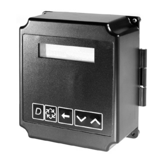
Red LED- Illuminates when there is an error. Flow Indicator A rotating line (appearing as a rotating star shape) will display on the screen when flow is going through the meter. TIMER DISPLAY - SCREEN EXAMPLES 3200 NXT FE12 • 5... -
Page 6: (System 4 Through 6)
TRANSFORMER AND GROUND 1. Locate the ground label to find the screw to attach the ground wire on the transformer. 2. Remove the screw and attach the ground wire, and re-attach the screw. NETWORK/COMMUNICATION CABLES 6 • 3200 NXT FE12... -
Page 7: Master Programming Mode Flow Chart
Options: 2 Valves in the System (Default) 3 Valves in the System 4 Valves in the System 3200 NXT FE12 • 7 Range: 2 to 4 Valves in the System NOTE: This screen will not display for System Type 4. - Page 8 #1. System size must be 3 or 4 to appear. Use the Shift button to move one #1. Use the Shift button to change each decimal position. space to the left. 8 • 3200 NXT FE12 TRIP DELAY 1: TRIP POINT 3:...
- Page 9 Liters (Metric Format) Range: 1 to 999 gallons in U.S. Format Range: 1 - 255Gallons (U.S. Format) 3200 NXT FE12 • 9 1 to 9.999 L in Metric Format 0.1 - 09.9 L (Metric Format) Pulses: 1 - 255 NOTE: Only displayed on units that physically have a meter (Lead always has a meter).
-
Page 10: User Programming Mode Flow Chart
NOTE: If a System 6, Unit #1 of “Tank Remaining” will display “System Remaining”. REGENERATION DAY Example: VALVE ADDRESS OVERRIDE:99 DAYS Controller unit number. Example: VERSION: REGENERATION Installed software level of the controller in use. X.XX TIME: 02:00AM 10 • 3200 NXT FE12... - Page 11 3200 NXT FE12 • 11...
-
Page 12: 2750/2850/2900S Upper & 2900S Lower Powerhead Assembly
2750/2850/2900S UPPER & 2900S LOWER POWERHEAD ASSEMBLY 14 17 28 29 37 35 61501-3200NXT-2_Page2_REVA 12 • 3200 NXT FE12... - Page 13 32 ....7 ..10872 ....Screw, Hex Wsh, 8-32 X 17/64 33 ....1 ..18709 ....Backplate, Lower 34 ....1 ..11381 ....Pin, Roll, 2900/3900 35 ....1 ..14759 ....Link, Piston Rod 36 ....1 ..14769 ....Bracket, Motor, 2900 37 ....1 ..14775 ....Cam, Drive, 2900 3200 NXT FE12 • 13...
-
Page 14: 3150/3900 Upper & Lower Powerhead Assembly
3150/3900 UPPER & LOWER POWERHEAD ASSEMBLY 32 52 10 8 27 26 11 61501-3200NXT-3_Pg2_REVA 14 • 3200 NXT FE12... - Page 15 36 ....1 ..19121 ....Meter Cable Assy, 3200NT ..19121-08 ...Meter Cable Assy, NT, 35” W/ Connector ..19121-09 ...Meter Cable Assy, NT, 99.5” W/ Connector ..19121-10 ...Meter Cable Assy, NT, 303.5” W/ Connector 3200 NXT FE12 • 15...
-
Page 16: Meter Assembly Plastic
19 ....3 ..42241-11 ....Connector Assy, 1-1/2" BSP, ..61560-14....Meter Assy, 1-1/2" INLN, BSP, Plastic, w/O-Ring ELEC, PLAS, PLAS Nipples, TURB Not Shown ..19791-02....Meter Cable Assy, Turbine 35" ..19791-04....Meter Cable Assy, Turbine 100" ..19791-05....Meter Cable Assy, Turbine 304" 16 • 3200 NXT FE12... -
Page 17: 1" Meter Assembly Brass
..60613-20 ...Meter Assy, 1" Inline, BSP, Electronic, Brass, PDL Not Shown ..19121-08 ...Meter Cable Assy, NT, 35", w/ Connector ..19121-09 ...Meter Cable Assy, NT, 99.5", w/ Connector ..19121-10 ...Meter Cable Assy, NT, 303.5" w/ Connector 3200 NXT FE12 • 17... -
Page 18: 1-1/2" Meter Assembly Brass
..60614-01NP ..Meter Assy, 1-1/2" INLN, NPT, ELEC, BRS BDY, NP, PDL, 1" ..60614-20 ...Meter Assy, 1-1/2" INLN, BSP, ELEC, BRS BDY, PDL, 1" SLV ..60614-20NP ..Meter Assy, 1-1/2" INLN, BSP, ELEC, BRS BDY, NP, PDL, 1" 18 • 3200 NXT FE12... -
Page 19: 2" Meter Assembly Brass
..60615NP ...Meter Assy, 2" INLN, NPT, ELEC, NP, PDL, 1.5" SLV ..60615-20 ...Meter Assy, 2" INLN, BSP/MET, ELEC, BRS, PDL, 1.5" SLV ..60615-20NP ..Meter Assy, 2" INLN, BSP/MET, ELEC, NP, PDL, 1.5" SLV 3200 NXT FE12 • 19... -
Page 20: 3" Meter Assembly Brass
13 ....6 ..12473 ....Screw, Hex Washer Head, #10- 24 x 0.625 14 ......60617 ....Meter Assy, 3" INLN, NPT, Electronic, BRS BDY, Paddlewheel ..60617-10 ...Meter Assy, 3" INLN, BSP, Electronic, BRS BDY, Paddlewheel 20 • 3200 NXT FE12... -
Page 21: Single Piston Wiring Diagram
BVCAM - BRINE VALVE CAM FM - FLOW METER (OPTIONAL) M1 - MOTOR OR PUMP (OPTIONAL) S1 - SOLENOID VALVE (OPTIONAL) NOTE: 1. TRANSFORMER FUSE - 5A 250V SLOW-BLOW P/N 41143 42140_Rev D 2. VALVE SHOWN IN SERVICE 3200 NXT FE12 • 21... -
Page 22: Dual Piston Wiring Diagram
BVCAM - BRINE VALVE CAM FM - FLOW METER (OPTIONAL) M1 - MOTOR OR PUMP (OPTIONAL) S1 - SOLENOID VALVE (OPTIONAL) NOTE: 42140_Rev C 1. TRANSFORMER FUSE - 5A 250V SLOW-BLOW P/N 41143 2. VALVE SHOWN IN SERVICE 22 • 3200 NXT FE12... -
Page 23: Remote Timer Wiring Diagram
UPPER DRIVE BLUE ORANGE ORANGE/BLACK STRIPE 31.8 BLACK 1.25 BLACK/WHITE STRIPE RED/WHITE STRIPE GREEN/WHITE STRIPE GREEN BACKPLATE GROUND SCREW CABLE ENTRY SEAL AMP P/N 54012-1 CONNECTOR PLUG CONNECTOR AMP #211770-2 FRONT VIEW WITH AMP SOCKET #66104-8 3200 NXT FE12 • 23... -
Page 24: 2750/2850 Remote Timer Wiring Diagram
SCAM - VALVE STEP CAM LOCKOUT SWITCH SW1 - VALVE HOMING SWITCH (OPTIONAL) SW2 - VALVE STEP SWITCH SENSOR SWITCH LD SWITCH - LOWER DRIVE SWITCH (OPTIONAL) NOTE: VALVE SHOWN IN SERVICE POSITION. FLOW METER (OPTIONAL) 24 • 3200 NXT FE12... -
Page 25: 2900 Remote Timer Wiring Diagram
M1 -OPTIONAL MOTOR/PUMP ON DURING REGENERATION OR CPO DEVICE ON DURING SERVICE(N.O. OUTPUT) TYPICAL INPUT WIRING TB2-ORANGE P/N 19781 +5 VDC DC GROUND LOCKOUT INPUT SENSOR INPUT SHIELD GREEN METER INPUT LOCKOUT SWITCH (OPTIONAL) SENSOR SWITCH (OPTIONAL) FLOW METER (OPTIONAL) 3200 NXT FE12 • 25... -
Page 26: 3900 Remote Timer Wiring Diagram
OR CPO DEVICE ON DURING SERVICE(N.O. OUTPUT) LOWER DRIVE TYPICAL INPUT WIRING TB2-ORANGE P/N 19781 +5 VDC DC GROUND LOCKOUT INPUT SENSOR INPUT SHIELD GREEN METER INPUT LOCKOUT SWITCH (OPTIONAL) SENSOR SWITCH (OPTIONAL) FLOW METER (OPTIONAL) 26 • 3200 NXT FE12... -
Page 27: 3150 Remote Meter Wiring Diagram
M1 -OPTIONAL MOTOR/PUMP ON DURING REGENERATION OR CPO DEVICE ON DURING SERVICE(N.O. OUTPUT) TYPICAL INPUT WIRING TB2-ORANGE P/N 19781 +5 VDC DC GROUND LOCKOUT INPUT SENSOR INPUT SHIELD GREEN METER INPUT LOCKOUT SWITCH (OPTIONAL) SENSOR SWITCH (OPTIONAL) FLOW METER (OPTIONAL) 3200 NXT FE12 • 27... -
Page 28: Troubleshooting
Connect wire harness to cycle switch. minutes Check Cycle Micro Switch. CHG on screen for more than 2 Control programmed incorrectly as 2900 or 3900 valve type. Reprogram unit as Stager Valve type. minutes © 2012 Pentair Residential Filtration, LLC 41693 Rev H AP12...
Need help?
Do you have a question about the 3200 NXT and is the answer not in the manual?
Questions and answers