Table of Contents
Advertisement
Advertisement
Table of Contents

Related Manuals for Harbor Freight Tools CEN-TECH 41080


Summary of Contents for Harbor Freight Tools CEN-TECH 41080
-
Page 2: Table Of Contents
CONTENTS PAGE SAFETY INFORMATION ….………………………………………………… SAFETY SYMBOLS .……………………………………………………….. SAFETY PRECAUTIONS ………………………………………………….. MAINTENANCE .……………………………………………………………. GENERAL DESCRIPTION …..……………………………………………. FRONT PANEL DESCRIPTION …..………………………………………. OPERATING INSTRUCTIONS ……………………………………………. SPECIFICATIONS …...…………………………………………………….. REPLACING THE BATTERY ...……………………………………………. ACCESSORIES …………………………………………………………….. -
Page 3: Safety Information
SAFETY INFORMATION The digital clamp meter has been designed according to IEC1010 – 1 and IEC1010 – 2 – 032 concerning safety requirements for electrical measuring instruments and hand – held current clamps with an overvoltage category (CAT II) and pollution 2. SAFETY SYMBOLS Important safety information, refer to the operating manual. -
Page 4: Maintenance
• Read these operating instructions thoroughly and completely before operating your meter. Pay particular attention to WARNINGS, which will inform you of potentially dangerous procedures. The instructions in these warnings must be followed. • Always inspect your meter and test leads for any sign of damage or abnormality before every use. -
Page 5: General Description
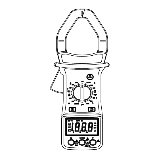
• Do not attempt calibration or service unless trained and another person capable of rendering first aid and resuscitation is present. GENERAL DESCRIPTION The meter is a handheld 3 1/2 digital clamp meter for measuring DC and AC voltage, AC current, Resistance and Continuity Test with battery operated. FRONT PANEL DESCRIPTION Transformer jaws Pick up the AC current flowing through the conductor. - Page 6 This measurement function is used to measure the maximum value of a signal. It is usable with AC/DC voltage, AC current and resistance measurements. To use this function, select the function and range and press the MAX button. When this is done, the “MAX” annunciator will appear in the display.
- Page 7 CLAMP METER LAYOUT...
-
Page 8: Operating Instructions
OPERATING INSTRUCTIONS DC VOLTAGE MEASUREMENT Connect the red test lead to the “V” jack and the black lead to the “COM” jack. Set rotary switch at desired 1000V position. Connect test leads across the source or load being measured. Read voltage value on the LCD display along with the polarity of the red lead connection. -
Page 9: Specifications
when measuring 1000MΩ resistance the display reading will be 1010 £ and the correct measuring result should be 1010 10 = 1000 MΩ. AUDIBLE CONTINUITY TEST Connect red test lead to “Ω” jack, black test lead to “COM” jack. Set range switch to “ ”... -
Page 10: Replacing The Battery
AC VOLTAGE Range Resolution Accuracy ±2.0 % of rdg ± 5 digits 750V Input Impedance: < 10MΩ Frequency range: 40Hz to 400Hz. Response: Average responding, calibrated in rms. of a sine wave. AC CURRENT Range Resolution Accuracy < 600A ±2.0% of rdg ± 5 digits 200A 0.1A >... -
Page 11: Accessories
The Clamp is used only for reading AC amperages between the receptacle and power cord. The Clamp must be used with a Line Splitter to do this. Line Splitters can be purchased at an electrical supply outlet. NOTE: Line Splitter, Item 92072 is available from Harbor Freight Tools.
Need help?
Do you have a question about the CEN-TECH 41080 and is the answer not in the manual?
Questions and answers