
Related Manuals for Powrmatic PZN 12


Summary of Contents for Powrmatic PZN 12
- Page 1 Doc Ref: M107 Issue 1.3 Sep 2018 ® User, Installation & Servicing Manual Issue 1.3 September 2018 w w w . p o w r m a t i c . c o . u k...
- Page 2 1. The appliance type and serial number. 2. The original commissioning documentation. As much detail as possible on the fault. 3. Your supplier, or installer, will then contact Powrmatic to make a guarantee claim on your behalf. Conditions of Guarantee 1.
-
Page 3: Table Of Contents
Contents Users, Installation and Servicing Instructions CONTENTS Title Section Contents Page User Instructions Pre Installation Introduction Duties Dimensions Technical data General Requirements Installation Fitting the unit Electrical Cable Installation Wiring Diagrams Commissioning and Testing Servicing Additional Documents Fault Finding page no. 3 of 28 PZN Aquamatic Water Heater Doc Ref M107 issue 1.3 Sep 2018. -
Page 4: User Instructions
Ensure boiler is operational and check valves are open. unit malfunctioning. B) Operating the Unit All Powrmatic units use electricity to power them, they may also contain moving parts. It would be hazardous • Switch on the electrical supply at the isolator. - Page 5 If in doubt • Do not insert foreign objects through the grille in the consult Powrmatic Technical Department. cover. • Do not touch the heat exchanger battery with naked Warnings hands.
- Page 6 Technical Specification Model 13.3 17.3 17.7 23.8 22.0 28.5 27.4 35.4 31.9 Thermal Power ¹ kcal/h 11440 14880 15220 20470 18920 24510 23560 30440 27430 Rows Axial Fan rotations 1400 - 900 - 700 ³ Airflow Rate m³/h 1750 1550 2450 2300 2800...
-
Page 7: Dimensions
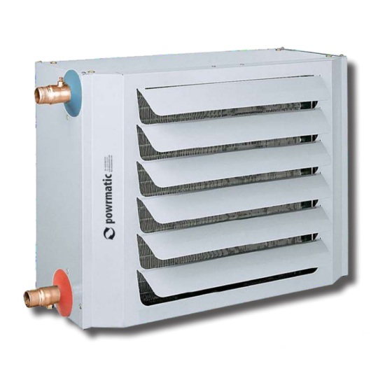
Dimensions Model 1205 1405 1139 Weight kg Water fitting dimensions Warning: For optimum performance it is essential that water inlet-outlet directions always be observed as indicated by the adhesive label. Model Ø male 1¼ 1¼ page no. 7 of 28 PZN Aquamatic Water Heater Doc Ref M107 issue 1.3 Sep 2018. -
Page 8: Technical Data
1.2 Technical Data PZN 12 & 13, Single Phase 230V ~ 50Hz, Water Temp @ 85 - 70°C. Fan heater at MAXIMUM fan speed. Airflow Rate °C 12.2 Thermal Power Kcal/h 11450 10450 9450 Air Flow Rate m³/h 1750 Sound Pressure Level... - Page 9 1.2 Technical Data PZN 22 & 23, Single Phase 230V ~ 50Hz, Water Temp @ 85 - 70°C. Fan heater at MAXIMUM fan speed. Airflow Rate °C 17.7 16.2 14.7 Thermal Power Kcal/h 15250 13900 12600 Air Flow Rate m³/h 2450 Sound Pressure Level dB(A)
- Page 10 1.2 Technical Data PZN 32 & 33, Single Phase 230V ~ 50Hz, Water Temp @ 85 - 70°C. Fan heater at MAXIMUM fan speed. Airflow Rate °C 22.0 20.1 18.2 Thermal Power Kcal/h 18950 17300 15650 Air Flow Rate m³/h 2800 Sound Pressure Level dB(A)
- Page 11 1.2 Technical Data PZN 42 & 43, Single Phase 230V ~ 50Hz, Water Temp @ 85 - 70°C. Fan heater at MAXIMUM fan speed. Airflow Rate °C 27.4 25.0 22.6 Thermal Power Kcal/h 23550 21500 19450 Air Flow Rate m³/h 3600 Sound Pressure Level dB(A)
- Page 12 1.2 Technical Data PZN 52 & 53, Single Phase 230V ~ 50Hz, Water Temp @ 85 - 70°C. Fan heater at MAXIMUM fan speed. Airflow Rate °C 31.9 29.1 26.3 Thermal Power Kcal/h 27400 25000 22650 Air Flow Rate m³/h 3950 Sound Pressure Level dB(A)
- Page 13 1.2 Technical Data PZN 62 & 63, Single Phase 230V ~ 50Hz, Water Temp @ 85 - 70°C. Fan heater at MAXIMUM fan speed. Airflow Rate °C 39.1 25.6 32.2 Thermal Power Kcal/h 33600 30650 27700 Air Flow Rate m³/h 5200 Sound Pressure Level dB(A)
- Page 14 1.2 Technical Data PZN 72 & 73, Three Phase 230V ~ 50Hz, Water Temp @ 85 - 70°C. Fan heater at MAXIMUM fan speed. Airflow Rate °C 47.4 43.3 39.2 Thermal Power Kcal/h 40800 37250 33700 Air Flow Rate m³/h 6700 Sound Pressure Level dB(A)
- Page 15 1.2 Technical Data PZN 83, 92 & 93, Three Phase 400V ~ 50Hz, Water Temp @ 85 - 70°C. Fan heater at MAXIMUM fan speed. Airflow Rate °C 87.8 80.1 72.4 Thermal Power Kcal/h 75550 68900 62250 Air Flow Rate m³/h 7700 Sound Pressure Level...
-
Page 16: General Requirements
1.3 General Requirements 1.3.1. General All heaters must be fitted exclusively with original accessories. The manufacturer shall not be held responsible for any damage deriving from improper use of the unit or from the use of non-original materials and accessories. All references to Law, standards, directives and technical rules in this manual are to be considered as informative only and valid at the date of printing of the Manual. - Page 17 1.3 General Requirements Note: Do not disperse the parts of the • position the unit on a dry level surface capable of packaging in the environment, or leave them sustaining its weight; within the reach of children, as they are potentially danger.
- Page 18 1.3 General Requirements Note: When mounting the heater on the ceiling Warning: Do not install outside and in places it is recommended that you use the CEILING with an aggressive environment. INSTALLATION KIT. Select the appropriate model on the basis of performance 1.3.6 Electrical Supply data for average fan speed.
-
Page 19: Fitting The Unit
2.1 Fitting the Unit 2.1.1 General protections (not supplied and to be provided by the customer) located upstream of the device need to be Before installation, check that the local distribution sized with an adequate margin that takes into account the conditions and adjustment of the appliance are normal variables of the system compatible. - Page 20 2.1 Fitting the Unit 2.1.5. Louvre Adjustment When the unit is delivered the directional louvres are almost completely closed. The horizontal louvres must be adjusted during installation so as to create an airflow suitable for the room/area being heated. Such airflow must not disturb the persons occupying such room/area.
-
Page 21: Electrical Cable Installation
2.2 Electrical Cable Installation 2.2.1. Electrical Connections Notes: Warning: THIS APPLIANCE MUST BE • Install upstream of the unit a differential magneto EARTHED. thermal circuit breaker suitably sized according to the regulations in force. Warning: Wiring external to the unit must be •... -
Page 22: Wiring Diagrams
² Wire cross-section ensures a voltage drop of less than 5% for a length of 30 m 2.3 Wiring Diagrams 2.3.1 External Wiring Details PZN 12 - 63 2.3.2 External Wiring Details PZN 72 - 93 page no. 22 oF 28 PZN Aquamatic Water Heater Doc Ref M107 issue 1.3 Sep 2018. - Page 23 2.3 Wiring Diagrams 2.3.3 External Wiring Details PZN 82 - 93 with two fans without connecting box 2.3.4 External Wiring Details PZN 82 - 93 with two fans with connecting box page no. 23 of 28 PZN Aquamatic Water Heater Doc Ref M107 issue 1.3 Sep 2018.
-
Page 24: Commissioning And Testing
2.3 Wiring Diagrams 2.3.5 Water circuit Diagram OUTPUT 1. Helical fan(s) 2. Water-air exchanger 3. Manual air bleed 4. Spherical check valve (not supplied) WARNING: Install a drain valve at the lowest point in the water circuit to empty the system when necessary. -
Page 25: Servicing
2.5 Servicing WARNING: Always switch off and disconnect • Checking the pressure of the system electricity supply and close the water check Regularly check the pressure of the system, so as to valve before carrying out any servicing work allow the unit to operate in optimal conditions. or replacement of failed components. - Page 26 STRUCTURE water from the system with the aid of compressed air. Structure of Heater Types 1 14 2.5.5.1 PZN 12 - 73 WARNING: If the system contains anti-freeze the water must be collected and, where possible, re-used. Do not dump as with...
-
Page 27: Fault Finding
3.1 Fault Finding 38.0 TROUBLESHOOTING PROBLEM CAUSE SOLUTION THE FAN DOES NOT START No power Check unit is powered Main switch turned to OFF Turn to ON Room thermostat faulty Check room thermostat Fan faulty ... - Page 28 Energy Association Powrmatic pursues a policy of continues improvement in both design and performance of its products and therefore reserves the right to change, amend or vary specifications without notice. Whilst the details contained herein are believed to be correct they do not form the basis of any contract and interested parties should contact the Company to confirm whether any material alterations have been made since publication of this brochure.
Need help?
Do you have a question about the PZN 12 and is the answer not in the manual?
Questions and answers