
Subscribe to Our Youtube Channel
Related Manuals for Powrmatic NCA-G Series


Summary of Contents for Powrmatic NCA-G Series
- Page 1 The NCA-G Range Installation and Servicing Instructions WARNING: THIS APPLIANCE MUST BE EARTHED £2.50 When supplied separately. NCA-G Range Issue 4 Feb 1999...
-
Page 2: Table Of Contents
Section Title Page Introduction Technical Data General Requirements Installation Air Distribution System Commissioning & Testing Servicing Connections to Powrmatic External Controls Fault Finding Short List of Parts Tables Title Page Dimensions Performance Data Burner Pressures - Natural Gas Group H - G20... -
Page 3: Introduction
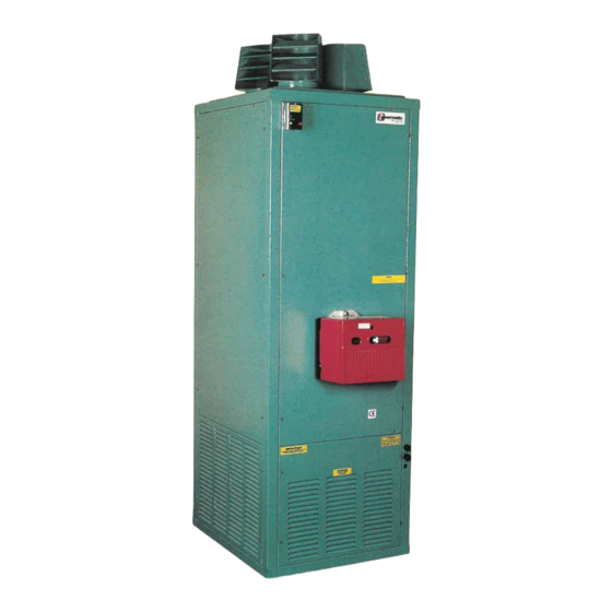
. INTRODUCTION The Powrmatic NCA-G range of gas fired forced draught, closed flue, fanned circulation air heaters cover a heat output range of 29.3 kW (100000 Btu/h) to 88.0 kW (300000 Btu/h) and are intended primarily for heating commercial or industry premises. -
Page 4: Technical Data
NCA-G 300 100.0 88.0 1.5575 3 0 4 Table 3.1 - Burner Pressures - Natural Gas - Group H - G20 - NetCV (Hi) = 34.02MJ/m³ Powrmatic Burners Riello Burners Start Gas Main Burner Start Gas Main Burner Gas Rate... -
Page 5: General Requirements
Table 4 Electrical Loadings Standard Larger Horsepower Motor NOM. PLATE START FUSE NOM. PLATE START FUSE MOTOR AMPS AMPS AMPS RATING MOTOR AMPS AMPS AMPS RATING MODEL ph R.P.M. R.P.M. NCA-G 100 1000 NCA-G 150 NCA-G 200 10.0 1000 NCA-G 300 18.0 General Requirements 3.3.2 Meters... -
Page 6: Installation
Advice in these instances taken of the working environment and the air temperatures may be obtained from Powrmatic Ltd. which will result when the overheat limit thermostat is being commissioned. Where inter-joist spaces are used as duct... -
Page 7: Air Distribution System
Connection of Air Heater(s) to Flue System temperature is concerned. Draughty areas, areas subjected to direct heat e.g. from the sun, and areas where the air A single wall Tee piece is supplied with each heater and must movement is relatively stagnant e.g. in recesses, are all be fitted to the flue outlet socket on the heater. -
Page 8: Servicing
Fig 1 Gas Controls Schematics 1st Main Gas 2nd Main Gas Safety Shut-off Safety Shut-off Valve Valve Pressure Test Point To Burner Inlet Main Gas Governor Fig 2a Gas Controls Layout NCA-G 100, 150 1) 1st Main gas safety shut off valve. 2) 2nd Main gas safety shut off valve. -
Page 9: Honeywell L4064N
1. Remove the electrical supply plug, 2. Release the unions on the connections at each end of the Connections to Powrmatic External Controls assemby and remove complete assembly. Fit new assembly in reverse order ensuring the valve assembly is correctly orientated for the direction of gas flow. -
Page 10: Fault Finding
Fault Finding R e f e r a l s o t h e b u r n e r s u p p l e m e n t s u p p l i e d w i t h t h e h e a t e r Fault... -
Page 11: Equivalent Resistance
Appendix A Calculation Of Flue System Equivalent Resistance The pressure resistance of the flue system (P ) can be calculated from Pr = 1.5 * [(PFF * H/D+SRF)Q Where Pressure resistance of the flue system in pa Pipe Friction Factor Effective flue height in m Internal Diameter of flue in m Sum of individual resistance factors... - Page 12 BSI Registered Firm FM 414 Ind. & Comm. Air Heaters; Air Moving Equipment; Flues & Chimneys; Natural Smoke & Heat Ventilators; Powered Supply & Extract Fans & Systems. HEATING DIVISION Winterhay Lane Ilminster, Somerset TA19 9PQ Tel: 01460 53535 Fax: 01460 52341 Every effort is made to ensure accuracy at time of going to press.
Need help?
Do you have a question about the NCA-G Series and is the answer not in the manual?
Questions and answers