Powrmatic OUH series User, Installation And Servicing Instructions
Hide thumbs
Also See for OUH series:
- User, installation & servicing manual (32 pages) ,
- User, installation & servicing manual (36 pages)

Related Manuals for Powrmatic OUH series


Summary of Contents for Powrmatic OUH series
- Page 1 The OUH Range Users, Installation and Servicing Instructions WARNING: THIS APPLIANCE MUST BE EARTHED OUH Range Users, Installation & Servicing Instructions Issue 4 March 2010...
- Page 2 7. Powrmatic ‘General Conditions of Sale’ have been observed. 8. Except for the obligation of Powrmatic Ltd to perform warranty repairs during the guarantee period, Powrmatic will not be liable in respect of any claim for direct or indirect consequential losses, including loss of profits or increased costs arising from loss of use of the appliance, or any event arising there from.
-
Page 3: Users Instructions
Approximately 2/3 minutes after the burner lights the heater All Powrmatic OUH heaters use oil and electricity to power fan will automatically start. When the external controls are satisfied the burner will be turned off and approximately 4/5 them, they may also contain moving parts such as pulley belts. -
Page 4: Table Of Contents
Installation & Servicing Instructions C O N T E N T S Section Title Page Introduction Technical Data General Requirements Installation of Heater Air Distribution System Commissioning & Testing Servicing Wiring Diagram Short List of Parts Figure Title Page Limit Thermostat Table Title Page... -
Page 5: Introduction
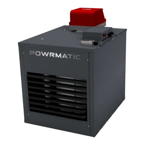
1. INTRODUCTION The Powrmatic OUH Range is a range of oil fired forced draught, closed flue, fanned circulation air heaters having an output range of 20kW to 60kW . The heaters are designed for suspension from suitable roof points, or alternatively mounted on purpose designed wall brackets, and are intended for heating commercial or industrial premises. -
Page 6: Technical Data
2. TECHNICAL DATA OUH20/F Front View Side View Rear View OUH20/C 50mm Front View Side View Rear View OUH30, 45 & 60/F Front View Side View Rear View OUH30, 45 & 60/C 50mm Front View Side View Rear View... - Page 7 Table 1. Dimensions Model Type OUH 20 OUH 30, 45 & 60 Note: D is the nominal flue diameter. Table 2 - Specifications HIGH FIRE MAXIMUM FUEL THROW DUCT NOISE WEIGHT INPUT VOLUME RESISTANCE MOTOR LEVEL INPUT OUTPUT (Net) MODEL kg/h m³/s dB(A) @ 3m...
-
Page 8: General Requirements
3. General Requirements Refer also to the detail provided in the burner handbook regarding pipe sizing. These must be generally in accordance with B S 799 Part 3 and BS 5410 Part 2. 3.1 Related Documents Particular attention is drawn to the following: Installation of air heaters must be in accordance with the relevant a) Pipe jointing compounds must be capable of withstanding requirements of:... -
Page 9: Installation Of Heater
4. Installation of Air Heater(s) Total Input Rating Air Vent Area of Air Heaters (Air direct-from outside) 4.1 General Up to 60kW 4.5 cm²/kW in excess of 7kW The air heater will be delivered to site pallet mounted and From 60kW up to 730kW 4.5 cm²/kW protected by plastic sheeting. -
Page 10: Electrical Connections
The flue terminal must not be installed so as to be less than: - 300mm below an opening e.g. window, air brick etc. - 200mm below eaves or gutter. - 300mm from an internal or external corner. - 1200mm from a surface facing the terminal. - 1500mm vertically from another terminal on the same wall. -
Page 11: Air Distribution System
5. Air Distribution System f) If a Powrtrol or MC200 is being used that the Winter mode is selected. 5.1 General 6.5 Lighting the Air Heater OUH/C and OUH/D models are designed for use with duct work Refer also to the burner instruction booklet. to more precisely define the point of air delivery, and /or provide 1. - Page 12 7.2 Burner Servicing/Maintenance nose pliers, before the replacement thermostat is installed. 5. Ensure that the fan and limit settings are as follows:- 1. Refer to the burner instruction booklet supplied with the Fan ON - 50°C, Fan OFF - 30°C heater and complete the servicing/maintenance instructions therein.
-
Page 13: Wiring Diagram
Lock out Indicator and reset 9. Short List of Parts Only originally specified parts may be fitted as service replacements. Please refer to Powrmatic Ltd for any parts not detailed in the listing below. ITEM USAGE PART # Fan & Limit Thermostat - Honeywell L4064N... - Page 14 BSI Registered Firm FM 414 Ind. & Comm. Air Heaters; Air Moving Equipment; Flues & Chimneys; Natural Smoke & Heat Ventilators; Powered Supply & Extract ISO 9001 Fans & Systems. HEATING DIVISION Hort Bridge Ilminster, Somerset TA19 9PS Tel: 01460 53535 Fax: 01460 52341 Every effort is made to ensure accuracy at time of going to press.
Need help?
Do you have a question about the OUH series and is the answer not in the manual?
Questions and answers