
Related Manuals for Powrmatic CPx Series


Summary of Contents for Powrmatic CPx Series
- Page 1 Doc Ref: M201 Issue 2.9 Nov 2018 ® User, Installation & Servicing Manual Issue 2.9 November 2018 ErP COMPLIANT S E P T E M B E R 2 0 1 8 w w w . p o w r m a t i c . c o . u k...
- Page 2 1. The appliance type and serial number. 2. The original commissioning documentation. As much detail as possible on the fault. 3. Your supplier, or installer, will then contact Powrmatic to make a guarantee claim on your behalf. Conditions of Guarantee 1.
-
Page 3: Table Of Contents
Contents Users, Installation and Servicing Instructions CONTENTS Title Section Contents Page User Instructions Pre Installation Introduction Duties Dimensions Accessories Head Plans Technical data General Requirements Installation Fitting the unit Fitting the flue General Identification of Items Electrical Cable Installation Wiring Diagrams Commissioning and Testing Servicing Additional Documents... -
Page 4: User Instructions
User Instructions 2) Oil-fired Heaters If the heater has not been left operational proceed as follows. IMPORTANT: If it is not possible to light the heater after 2/3 attempts contact the local service company. A) Checks before operating the Air 1. - Page 5 Combustible materials must not be stored adjacent to the heater. IMPORTANT All Powrmatic heaters use either gas or oil plus electricity to power them, they may also contain moving parts such as pulleys and belts. It would be hazardous to tamper with or attempt to service unless you are a competent person in the field of Gas and Electrical work.
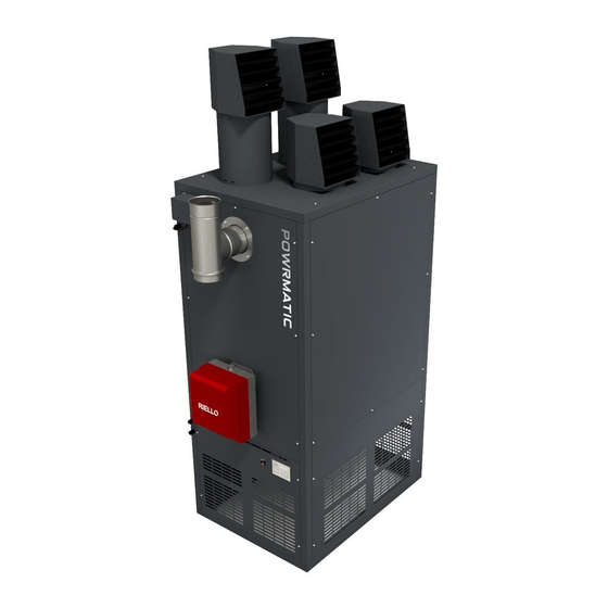
- Page 6 1.1 Introduction The Powrmatic CPx range of closed flue, fanned /RT - Rooftop heater with outlet duct spigot on the circulation air heaters cover a heat output range of 30 underside (inlet duct spigot optional). kW to 290kW and are intended primarily for heating /SD - Upright heater with side outlet duct spigot (inlet commercial or industrial premises.
-
Page 7: Technical Specification
Model 60 90 (gas) (oil) * For extended combustion duct lengths please contact Powrmatic Notes – • Fuel consumption and output figures based upon nett calorific values as follows - Class D light distillate fuel oil nett CV 36.28 MJ/l - Natural gas (G20) nett CV 34.02 MJ/m³... - Page 8 Dimensions CPx UD/UF Upright Free Blowing Upright Ducted (30-300) ØD Notes - • Flue tee provided as standard. Model 1200 1200 1399 1399 1599 1599 1104 1104 1767 1767 1895 1895 2149 2149 2265 2265 2265 2265 mm ø 1535 1535 1661 1661...
- Page 9 Dimensions CPx HD/HF Horizontal Free Blowing Horizontal Ducted (30-300) ØD Notes - • Flue tee provided as standard. • Screened air intake (SAI) fitted as standard on HF models. Duct spigot option available. • Direction of airflow to be specified at time of order. Left to Right (L-R when looking at the burner) airflow shown above. Model 1200 1200...
- Page 10 Dimensions CPx-EA External Cabinet Heaters (30-300) Upright models ØD 1 mtr Optional Fresh Air Intake Grille Horizontal models 1 mtr Optional Fresh Air Intake Grille Notes - • Direction of airflow to be specified at time of order. Left to Right (L-R when looking at the burner) airflow shown above. •...
- Page 11 Dimensions CPx UD/UF Upright Free Blowing Upright Ducted (360-590) Upright models ØD Section Split Line Notes - • The Heat Exchanger and Fan Section can be split on the ‘Section Split Line’ . • Flue tee provided as standard. Model 1915 2165 2715...
- Page 12 Dimensions CPx HD/HF Upright Free Blowing Upright Ducted (360-590) Horizontal models Section ØD Split Line Notes - • The Heat Exchanger and Fan Section can be split on the ‘Section Split Line’ . Flue tee provided as standard. • Direction of airflow to be specified at time of order. Right to Left (R-L when looking at the burner) airflow shown above.
- Page 13 Dimensions CPx-EA External Cabinet Heaters (360-590) Upright models 1 mtr ØD Section Split Line Notes - • The Heat Exchanger and Fan Section can be split on the ‘Section Split Line’ . • Return air via inlet duct spigot is standard. Optional fresh air grille is available. •...
- Page 14 Dimensions CPx-EA External Cabinet Heaters (360-590) Horizontal models 1 mtr Section Split Line Section ØD Split Line Notes - • The Heat Exchanger and Fan Section can be split on the ‘Section Split Line’ . Primary flue and cowl provided as standard. •...
- Page 15 Accessories Side/rear Inlet Spigots Filters Dampers SIDE REAR SIDE REAR SIDE REAR Model 1200 1200 1399 1399 1599 1599 1915 2165 2715 1105 1105 1098 1098 1300 1300 1500 1500 1815 2065 2615 1003 1003 1265 1165 Notes - • All dimensions are outside dimensions •...
-
Page 16: Technical Data
1.2 Technical Data Riello Burner Settings - Natural Gas - Group H - G20 Net CV (Hi = 34.02MJ/m³) Nominal Inlet Pressure = 20mbar Minimum Inlet Pressure = 17.5mbar High Fire Low Fire MODEL Burner Type Gas Control Burner Pressure Gas Rate Burner Pressure Gas Rate... - Page 17 1.2 Technical Data Riello Burner Settings - Propane G31 Net CV (Hi = 88.00MJ/m³) Nominal Inlet Pressure = 37mbar Minimum Inlet Pressure = 37mbar High Fire Low Fire MODEL Burner Type Gas Control Burner Pressure Gas Rate Burner Pressure Gas Rate mbar m³/h mbar...
- Page 18 1.2 Technical Data Riello Burner Settings - 35sec Oil - Diesel - Net CV (Hi = 42.69MJ/kg) High Fire Low Fire MODEL Burner Type Nozzle Burner Pressure Fuel Input Burner Pressure Fuel Input kg/h kg/h CPx30 RG1RKD 0.65 x 80S 13.44 2.70 8.96...
- Page 19 1.2 Technical Data Riello Burner Settings - 28sec Oil - Kerosene - Net CV (Hi = 47.00MJ/kg) High Fire Low Fire MODEL Burner Type Nozzle Burner Pressure Fuel Input Burner Pressure Fuel Input kg/h kg/h CPx30 RG1RKD 0.75 x 60S 10.0 2.70 1.89...
- Page 20 1.2 Technical Data Electrical Loadings Standard Motor Uprated Motor (fitted to EA models as standard) Nominal Start Fuse Nominal Start Fuse MODEL Motor Pha Motor Pha Motor Amps Amps Rating Motor Amps Amps Rating r.p.m r.p.m CPx30 0.55 1500 0.75 1500 15.9 CPx45...
- Page 21 1.2 Technical Data Drive Data - Standard Motor Motor Pulley Motor (a) Motor Pulley (b) Centrifugal Fan (d) TaperLock (c) MODEL kW Pha RPM Pt no. Size Pt no. Size Pt no. Size Pt no. CPx30 0.55 1500 270 x 270 1402CFAN150/T/15 CPx45 0.55...
- Page 22 1.2 Technical Data Drive Data - LHP (Larger Horsepower) Motor Motor Pulley Motor (a) Motor Pulley (b) Centrifugal Fan (d) TaperLock (c) MODEL kW Pha RPM Pt no. Size Pt no. Size Pt no. Size Pt no. CPx30 0.75 1500 140001520 95x1 SPA 142000602 1210-24 142003350 2 321 x 321...
-
Page 23: General Requirements
KW output heater is fitted (CIBSE elemental often if the problem is severe. methodology can be used, or the Powrmatic Technical Department can provide guidelines). 1.3.2 Location 1.3.4. Electrical Supply... -
Page 24: Gas Supply
1.3 General Requirements 1.3.6. Gas Fired Heaters 1.3.7. Gas Fired Heaters 1.3.6.1. Related Documents 1.3.7.1. Related Documents All Gas Fired CPx heaters comply with the following All Oil Fired CPx heaters comply with the following European Directives: European Directives: Energy Related Product Directive: 2009/125/EC* Energy Related Product Directive: 2009/125/EC*... - Page 25 1.3 General Requirements Ideally the return pipe should terminate within the oil tank heat input shall be provided at low level i.e. below the level at the same level as the suction line, both being below the of the heater flue connection. minimum oil level.
- Page 26 1.3 General Requirements 1.3.9. Air Distribution System maximum static resistance available for the specific model installed. (see table) 1.3.9.1. Freeblowing UF/HF/CF/RF If fitting horizontal ductwork, it is recommended that a These are equipped with rotatable air delivery heads fixed plenum box with the same external dimension as the duct to the top panel of the unit providing rotational and lateral spigot with a minimum height of 1.0m be fitted to the direction.
-
Page 27: Fitting The Unit
2.1 Fitting the Unit 2.1.1 Fitting space requirement Model Front 1250 1250 1450 1450 1650 1650 Rear 1000 Above 1000 Side (Blank panel)* Side (Louvred)* 1000 To the front The depth of the heater To the rear 1.0m To the side having louvred lower panels* 1.0m To the side having blank lower panels (see below)* 0.15m... -
Page 28: Installing The Heater
2.1 Fitting the Unit 2.1.2. General that the blank panel is facing the wall, interchanging the two side panels if necessary. Before installation, check that the local distribution conditions, fuel specification, and adjustment of the Any combustible material adjacent to the air heater and appliance (see data plate) are compatible. -
Page 29: Fitting The Flue
2.2 Fitting the Flue A single wall tee piece is supplied with each heater condensation pipe from the collection tray to the and must be fitted to the flue outlet socket on the disposal point should be of non-corrodible material of not less heater. -
Page 30: Electrical Cable Installation
2.4 Electrical Cable Installation 2.4.1. Electrical Connections Heaters supplied less main fan must be electrically interlocked to the air movement system so that this is started in the same manner as the air heater fan would be viz. A connection from the appropriate heater terminal Warning: THIS APPLIANCE MUST BE (see wiring diagram with the heater) must be made to one EARTHED. - Page 31 2.4 Electrical Cable Installation 2.4.3. Wiring The wiring terminals, both mains input and controller, are Mains input of either 230V 50Hz 1Ph or 415V 50Hz 3Ph located on the electrical chassis panel behind the bottom supply connections are via a separate terminal block. For front panel of the heater which firstly has to be removed.
- Page 32 2.4 Electrical Cable Installation 2.4.5. Optional Remote Controller The wiring terminals, both mains input and controller, are terminal 7 230V Heat Demand located on the electrical chassis panel behind the bottom terminal 8 230V Main Fan Only front panel of the heater which firstly has to be removed. terminal 9 Lockout indication - 230V Output terminal 10*...
-
Page 33: Wiring Diagrams
2.5 Wiring Diagrams 2.5.1 CPx30-90 1Pha Gas/Oil Heater Main Internal Wiring Diagram page no. 33 of 68 CPx Range Users, Installation & Servicing Instructions Doc Ref M201 issue 2.9 Nov 2018. - Page 34 2.5 Wiring Diagrams 2.5.2 CPx120-200 3Pha Gas/Oil Heater Main Internal Wiring Diagram page no. 34 of 68 x Range Users, Installation & Servicing Instructions Doc Ref M201 issue 2.9 Nov 2018.
- Page 35 2.5 Wiring Diagrams 2.5.3 CPx250-300 3Pha Gas/Oil Heater Main Internal Wiring Diagram page no. 35 of 68 CPx Range Users, Installation & Servicing Instructions Doc Ref M201 issue 2.9 Nov 2018.
-
Page 36: Commissioning And Testing
DO NOT use burner settings from the burner instruction booklet. The burners are Checks to ensure electrical safety must be carried out by specifically adjusted for Powrmatic heaters, a qualified person. only use the settings in these instructions. 2.6.2. Gas Installation (where applicable) 2.6.5.1.1. - Page 37 2.6 Commissioning and Testing iv) Burner goes to lockout as there is no gas supply. 3. Turn ON the main electricity supply and check that the following sequence of events occur. i) Burner fan runs. ii) Ignition spark is heard. iii) Main gas valves open and main 4.
- Page 38 The burners are Check for reliable burner operation, if the burner shuts specifically adjusted for Powrmatic heaters, down, reduce the value by a half set point. only use the settings in these instructions.
- Page 39 2.6 Commissioning and Testing WARNING: If any adjustments have been made, re-check both high and low fire once more. If continued unsuccessful ignition attempts are made it is possible to accumulate a significant quantity of oil and oil mist in the 2.6.5.2.2.1.2 CPx200 &...
- Page 40 2.6 Commissioning and Testing 2.6.5.2.2.1. Hi/Low Burners cont. 2.6.7. Soft Start (CPx250 & 300 only). 3. Measure the CO2 content of the flue gases. If Ensure that the soft start settings are nominally:- necessary adjust the combustion air damper of the burner Ramp Up - 8.2 (Refer to the Burner Instructions) to obtain a CO2 reading Ramp Down - 0...
-
Page 41: Servicing
2.7 Servicing Gas Safety (Installation & Use) (Amendment) section 2.6.6.4 disconnecting the flue and then removing Regulations the upper front panel of the heater exposes the heat exchanger front clean out panels. If the flue cannot be It is law that all gas appliances are installed, disconnected removal of the side panels exposes the adjusted and, if necessary, converted by upper front header side clean out plates. - Page 42 2.7 Servicing 2.7.6. Replacement of Faulty Components 2.7.6.1 Burner Components Refer to the burner instructions supplied with the heater for information regarding replacement of individual components within the burner. 2.7.6.2 Complete Burner Set-up If a burner has been replaced or substituted complete, the Head pressure is achieved by adjusting a screw which burner must be set up correctly.
- Page 43 2.7 Servicing For adjustment and setting of gas valve, refer to section 2.6.5.1.3 Correct operational start-up Start of heat demand. Burner begins the ignition cycle. 0s-4s The burner is in stand-by. 4s-44s Pre-purge with opened air damper Ignition 1st stage. 49s-69s Ignition 2nd stage.
- Page 44 2.7 Servicing Correct operational start-up Start of heat demand. Burner begins the ignition cycle. 0s-4s The burner is in stand-by. 4s-44s Pre-purge with opened air damper Ignition 1st stage. 47s-52s Ignition 2nd stage. 2.7.6.2.2 RGD (Oil) for CPxG30 to CPxG250 inc 1.
- Page 45 2.7 Servicing CPx 200 - CPx 250 ONLY terminal strip - see section 2.5 or the accompanying wiring diagram. Hi/Low operation works on the basis that either a single or both nozzles are open. Adjust the pump pressure by rotating the burner adjustment screw clockwise (+ 3.
- Page 46 2.7 Servicing 2.7.6.5. Fan/Limit Thermostat NOTE: CD/CF Counterflow heaters have two fan and limit thermostats fitted. Either one will start the main fan and either one will shut the burner down in the event of an overheat situation. Fan ON Mechanical Limiter Set Point Release Point...
-
Page 47: Fault Finding
3.1 Fault Finding 3.1.1. Heater General Fault Action 1. Check electrical supply is ON. 2. Check controls are ON or calling for heat. Heater does not turn on 3. Faulty burner control unit. 4. Limit thermostat open circuit/faulty, interlock relay not set/faulty. 5. - Page 48 3.1 Fault Finding FAULTS POSSIBLE CAUSES SOLUTION Check presence of voltage in the L1-N clamps of the 7 pin plug. Lack of electrical supply. Check the condition of the fuses. Check that safety thermostat is not lock out. Check the manual cock opening The burner doesn’t Lack of gas Check that the valves charge over to the opening position...
- Page 49 3.1 Fault Finding 3.1.1.2 BSD/RSD (Gas) for CPxGO30 to CPxG250 inc Lock-out due to ignition failure If the flame does not light within the safety limit (~ 5s) the burner locks-out. Lock-out is shown by a led on the appliance. MAXIMUM Total number of recycle trials is 3.
-
Page 50: List Of Parts
3.2 List of Parts Item Description CPx30 CPx45 CPx60 CPx90 CPx120 Riello Gas Burner BNR030CPxG BNR045CPxG BNR060CPxG BNR090CPxG BNR120CPxG NatGas c/w Valve /MK3/ERP /MK3/ERP /MK3/ERP /MK3/ERP /MK3/ERP & Lead Gas Valve 14292110 14292111 14292112 Burner Gasket 141937081 141937081 141930806 141937150 141937080 141930806 141930806... - Page 51 3.2 List of Parts Item Description CPx150 CPx175 CPx200 CPx250 CPx300 Riello Gas Burner BNR150CPxG BNR175CPxG BNR200CPxG BNR250CPxG BNR300CPxG NatGas c/w Valve /MK3/ERP /MK3/ERP /MK3/ERP /MK3/ERP /HILO/MK3 & Lead Gas Valve 14292113 14292114 14292105 Burner Gasket 141937150 141937082 142992790 141937150 141937150 142992790 Riello 35s Oil...
- Page 52 3.2 List of Parts Item Description CPx30 CPx45 CPx60 CPx90 CPx120 CPx0450201 CPx0450202 CPx0600201 CPx0900201 CPx1200201 CPx0450201 CPx0450201 CPx0600202 CPx0900202 CPx1200202 Swirlers 28 x CPx0900223 34 x CPx0900223 34 x CPx1500223 23 x CPx1500223 17 x CPx0900223 MC200 MC200CAB Controller Control CPX3-90/CP/ CPX3-90/CP/...
- Page 53 3.2 List of Parts Item Description CPx150 CPx175 CPx200 CPx250 CPx300 CPx1500201 CPx1750201 CPx2000201 CPx3000201 CPx3000201 CPx1500202 CPx1750202 CPx2000202 CPx3000202 CPx3000202 Swirlers 29x CPx1750223 59 x 1750223 59 x 3000223 59 x 3000223 46 x CPx1500223 23 x CPx1500223 29 x 1750223 29 x 1750223 29 x 1750223 MC200...
- Page 54 3.2 List of Parts Item Description CPx30 CPx45 CPx60 CPx90 CPx120 Electrode 142992991 142992990 Sensor Probe 142992989 142992987 Photocell 141979531 Electrode 142924310 142924311 HT Lead 142992998 142992999 Probe Lead 142992986 Speed Gear 141979551 Pump Coil 1 141979561 Coil 2 141979562 Pressure 145604651 142961108...
- Page 55 3.2 List of Parts Item Description CPx150 CPx175 CPx200 CPx250 CPx300 Electrode 142992990 142992988 141979104 Sensor Probe 142992987 142992894 Photocell 141979531 141979533 141979532 Electrode 142924311 142992793 HT Lead 142992998 142992998 142993001 142992999 142993000 142993002 Probe Lead 142992986 145604654 Speed Gear 141979551 141979552 142992633...
- Page 56 3.2 List of Parts Item Description CPx30 CPx45 CPx60 CPx90 GAS DD Fan Standard 1402CFAN150/T/15 1402CFAN140/T/15 1402CFAN210/T/15 Main Fan Standard 1402CFAN510/T 1402CFAN240/T 1402CFAN240/T 1402CFAN510/T 1402CFAN510/T Motor 140001908 Standard 140001520 140001520 140001998 140001998 Motor Pulley Standard 142001689 142000602 142000602 142001689 142001675 Motor T/lock 142003360 Standard...
- Page 57 3.2 List of Parts Item Description CPx90 OIL CPx120 CPx150 CPx175 DD Fan 1402CFAN560/ 1402CFAN580/ Standard T/15 T/15/3P Main Fan Standard 1402CFAN820/T 1402CFAN820/T 1402CFAN510/T 1402CFAN820/T 1402CFAN820/T 1402CFAN820/T Motor 140002055 140002108 Standard 140001908 140002055 140002108 140002206 Motor Pulley Standard 142000602 142000602 142001689 142000602 142000601...
- Page 58 3.2 List of Parts Item Description CPx200 CPx250 CPx300 DD Fan Standard Main Fan Standard 1402CFAN820/T 1402CFAN510/ 1402CFAN510/ T/2DECK T/2DECK 1402CFAN820/T Motor 140002108 140002108 140002251 Standard 140002206 140002206 140002610 Motor Pulley Standard 142000602 142001619 142001619 142000601 142001689 142001013 Motor T/lock 142003856 142161028 142003655...
-
Page 59: Fuel Conversion
3.3 Fuel Conversion 3.3.1. Oil Conversion 7. Refit all other components in reverse order. 8. Check that fitted fire valves are open. WARNING: Always switch off and disconnect 9. Refer to the burner instruction book and fit a pressure electricity supply and close the oil service gauge (and vent valve if the burner is on a single pipe oil valve before carrying out any servicing work feed) to the oil pump. - Page 60 3.3 Fuel Conversion Check that the High Fire burner pump pressure agrees Hi/Low operation works on the basis that either a single with that stated on the heater data plate and in section or both nozzles are open. Check that the burner pump 1.2.
- Page 61 3.3 Fuel Conversion Riello Burner Settings - 28sec Oil - Kerosene - Net CV (Hi = 47.00MJ/kg) Maximum Pump Suction = 0.4bar Burner Pressure High Fire Low Fire Kit part number MODEL Nozzle Type p.s.i. p.s.i. CPx30 0.75 x 60S CPX30HL/28 10.0 101.5...
-
Page 62: Gas Conversion
3.3 Fuel Conversion 3.3.2. Gas Conversion 3. Unscrew and remove the screws (5), pull out the head assembly support (6) turning it slightly to the right, taking care not to change the setting position on the elbow- Gas Safety (Installation & Use) (Amendment) bracket during dismantling. - Page 63 3.3 Fuel Conversion Natural Gas to Propane (LPG) Conversion Data Nominal Inlet Pressure = 37mbar, Minimum Inlet Pressure = 37mbar Burner Pressure High Fire Low Fire Conversion Kit part number MODEL mbar mbar CPx30 CPX30HL/LPG CPx45 CPX45HL/LPG 10.2 CPx60 CPX60HL/LPG CPx90 CPX90HL/LPG CPx120...
-
Page 64: Information Required For Ecodesign (Erp) Directive 2009/125
Seasonal Space Heating Energy Efficiency Seasonal Efficiency figure based on table 16 of the "Non-Domestic Building Services Compliance Guide". Extra efficiency credits are available for High/Low burners and controlling via the Powrmatic MC200. Excluding Distribution Fan page no. 64 of 68... -
Page 65: Calculation Of Flue System Equivalent Resistance
Appendices Calculation of flue system equivalent resistance The pressure resistance of the flue system (Pr) = 1.5 * [(PFF*H/D+SRF)Qm/Wm2] (pa) Where H = Effective flue height in m D = Internal Diameter of flue in m PRF (Pipe Friction Factor) = 0.118*(0.21147/D0.4) Where D = Internal Diameter of flue in m SRF (Sum of individual resistance factors) Typical resistance factors for individual components are as follows:... - Page 66 Notes: page no. 66 of 68 x Range Users, Installation & Servicing Instructions Doc Ref M201 issue 2.9 Nov 2018.
- Page 67 Notes: page no. 67 of 68 CPx Range Users, Installation & Servicing Instructions Doc Ref M201 issue 2.9 Nov 2018.
- Page 68 Energy Association Powrmatic pursues a policy of continues improvement in both design and performance of its products and therefore reserves the right to change, amend or vary specifications without notice. Whilst the details contained herein are believed to be correct they do not form the basis of any contract and interested parties should contact the Company to confirm whether any material alterations have been made since publication of this brochure.
Need help?
Do you have a question about the CPx Series and is the answer not in the manual?
Questions and answers