Powrmatic VPC 30 User, Installation And Service Manual
Vpc series
Hide thumbs
Also See for VPC 30:
- User, installation and servicing instructions (24 pages) ,
- User, installation & servicing manual (40 pages)

Related Manuals for Powrmatic VPC 30


Summary of Contents for Powrmatic VPC 30
- Page 1 The VPC Range User, Installation and Servicing Instructions WARNING: THIS APPLIANCE MUST BE EARTHED £2.50 When supplied separately. VP Classic Range Users, Installation and Servicing Instructions Issue 2 April 2009...
- Page 2 7. Powrmatic ‘General Conditions of Sale’ have been observed. 8. Except for the obligation of Powrmatic Ltd to perform warranty repairs during the guarantee period, Powrmatic will not be liable in respect of any claim for direct or indirect consequential losses, including loss of profits or increased costs arising from loss of use of the appliance, or any event arising there from.
-
Page 3: Users Instructions
1. Set the controls to call for heat and the ignition start up sequence will commence. The internal exhaust fan will run. All Powrmatic heaters use gas and electricity to power them, When sufficient combustion airflow is proved by the air pressure they may also contain moving parts such as pulley belts. - Page 4 CONTENTS Section Title Page Introduction Technical Data General Requirements Installation Air Distribution System Commissioning & Testing Servicing Fault Finding Flow Chart Wiring Diagrams Short List of Parts Tables Title Page Dimensions Specifications Injector Sizes & Burner Pressures Natural Gas - Group H - G20 Electrical Loadings 1ph Figure Title...
-
Page 5: Introduction
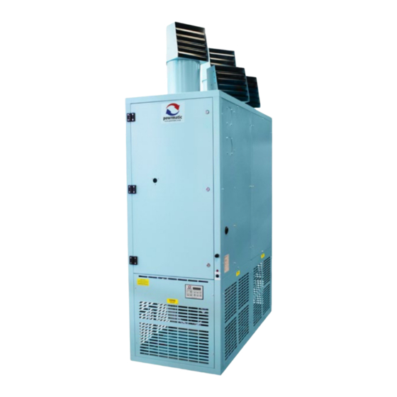
1. INTRODUCTION The VPC range are highly efficient gas fired, fanned circulation floor standing air heaters that cover heat outputs of 30kW to 130kW. The units have a single closed flue system that can be either vertical or horizontal and feature a single burner assembly which, as standard is ON/OFF but can also be supplied in High/Low or Modulating formats. -
Page 6: Technical Data
Gas entry VPC 130UF shown Front View Sidet View Table 1. Dimensions Unit Side Duct Spigot Top Duct Spigot VPC 30 1676 658(h) x 658(w) 648(h) x 658(l) 1108 VPC 52 1046 2132 VPC 80 1412 658(h) x 960(w) -
Page 7: Specifications
WEIGHT VOLUME MOTOR LEVEL INPUT INPUT @ Std. Airflow c/w Heads OUTPUT OUTPUT (Nett) (Nett) MODEL m³/s dB(A) @ 3m VPC 30 0.370 60.0 32.6 30.0 18.0 15.7 0.8664 VPC 52 0.55 68.0 56.5 52.0 30.4 26.1 1.5884 VPC 80 76.0... -
Page 8: General Requirements
3. General Requirements of adequate size. Do not use pipes of a smaller size than the inlet gas connection of the heater. The complete installation must be tested for soundness as described in the above Code. 3.1 Related Documents 3.3.4. Boosted Supplies The installation of the air heater(s) must be in accordance with the rules in force and the relevant requirements of the Gas Safety Where it is necessary to employ a gas pressure booster the... -
Page 9: Electrical Supply
3.7 Electrical Supply 4.2 Fitting the Air Heater Wiring external to the air heater must be installed in accordance If necessary consideration should be given to mounting the with the I.E.E. Regulations for Electrical Installations and any heater on resilient pads, or equivalent, to minimise transfer of local regulations which apply. -
Page 10: Gas Connection
(230V) via a room thermostat, time clock etc. Note:A terminal guard, as supplied by Powrmatic Ltd, must be All units must be earthed. The electrical supply must be run to fitted to horizontal flue terminals. -
Page 11: A. Exhaust Only System - Horizontal
Fig 2a Exhaust only system - horizontal Fig 3a Individual system - horizontal Single to twin Terminal Terminal Adjustable Lengths adaptor F l u e Flue socket length outlet Lengths Combustion air entry (fitted with inlet grille) Combustion air duct Adjustable length 12m maximum... -
Page 12: Electrical Installation
6. Commissioning & Testing h) Turn ON the gas supply. 6.4 Lighting the Air Heater 6.1 Electrical Installation NOTES: Checks to ensure electrical safety must be carried out by a 1. On initial lighting of the heater(s), it may take some time to qualified person. -
Page 13: Servicing
6.6.1.1 Standard Units Fig 8 High/Low and Modulating Head Low pressure 1. Set external controls to ensure that the main burner is off. Open the access door. Connect a pressure gauge to the burner setting screw pressure test point on the multifunctional control. Valve stem 2. -
Page 14: Heat Exchanger
NB. Ensure that the thermostats are set correctly before fitment 7.3 Ignition and Rectification Electrodes Limit Thermostat settings:- VPC 30, 52 90°C 1. Inspect the electrodes, making sure that they are in a sound VPC 80 80°C... -
Page 15: Fault Finding Flow Chart
8. Fault Finding Flow Chart START Gas & Electrical Turn supplies on supplies present at heater Check fuses/connections 230V at ‘Heat’ terminal on PCB Check control circuit (Time clock/thermostats) calling for heat Voltage at limit stat 1 on PCB Check Fuse 1 Faulty PCB Failed Replace... -
Page 16: Wiring Diagram
See the wiring diagram supplied with the heater 10. Short List of Parts Only originally specified parts may be fitted as service replacements. Please refer to Powrmatic Ltd for any parts not detailed in the listing below. ITEM USAGE PART #... - Page 17 BSI Registered Firm FM 414 Ind. & Comm. Air Heaters; Air Moving Equipment; Natural Smoke & Heat Ventilators; Powered Supply & Extract Fans & Systems. ISO 9001 HEATING DIVISION Hort Bridge Ilminster, Somerset TA19 9PS Tel: 01460 53535 Fax: 01460 52341 Every effort is made to ensure accuracy at time of going to press.
Need help?
Do you have a question about the VPC 30 and is the answer not in the manual?
Questions and answers