Advertisement
Quick Links
Advertisement

Related Manuals for BAS-IP AV-07T


Summary of Contents for BAS-IP AV-07T
- Page 1 The individual outdoor panel BAS-IP AV-07T The instruction manual...
- Page 2 Page 2 Note For the correct installation, follow the instructions. If you have any difficulty with installation and operation, please contact your dealer for advice. The technical parameters and specifications mentioned here may vary slightly from those stated in the instructions of the devices. This is our company conducts constant upgrading and improvement of the functionality to improve the characteristics of current devices.
-
Page 3: Table Of Contents
Page 3 CONTENT Appearance Main functions Technical parameters Equipment Settings through the WEB interface Connection scheme Mounting scheme Attachment 1 Notes... -
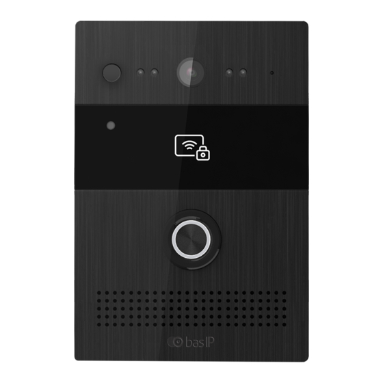
Page 4: Appearance
Page 4 APPEARANCE Model: AV-07T... -
Page 5: Main Functions
Page 5 MAIN FUNCTIONS BAS-IP AV-07T Interface WEB-interface Lock opening By card, with the monitor Access control Combined contactless card reader: EM-Marin and MIFARE Integration with ACS Wiegand-26, Wiegand-34 Input / Output Quick dial buttons 1 piezoelectric ring button Number of ringtones... -
Page 6: Technical Parameters
Page 6 TECHNICAL PARAMETERS BAS-IP AV-07T Panel type Individual Screen Matrix size 1/4’’ Angle 122° horizontal ° vertical x 56 Matrix resolution 2 MP Output video 720p (1280x720) H.263, H264, MJPEG Night backlight 4 IR LEDs Light sensitivity 0.01 Protection class... -
Page 7: Equipment
Page 7 EQUIPMENT Outdoor panel Sealing rubber Protective shroud Sealing ring М2.5х6.5 – М2.5х6.5 screws for Allen wrench М3х5 – М3х5 screws for Phillips head screwdriver Allen wrench Strap for installation work Flush-mounting bracket... - Page 8 Page 8 EQUIPMENT Built-in box for flush mounting Screws for Phillips head screwdriver: M4x10 and ST4x20 Plastic dowels Wall-mounting bracket (not included)
- Page 9 “AV07T Device manager” to determine an IP address of the outdoor panel: Press the “Scan” button and program window will display IP addresses of all AV-07T outdoor panels, which are connected to the local network. It is possible to change the basic network...
- Page 10 Page 10 SETTINGS THROUGH THE WEB INTERFACE To configure the outdoor panel remotely via the WEB interface and to set the virtual numbers, you need to connect to it via Internet-browser on your PC. The outdoor panel should be connected to the same network segment, as the PC, from which it is planned to customize the outdoor panel.
- Page 11 Page 11 SETTINGS THROUGH THE WEB INTERFACE Select account: Account which is used for calls. Dialing if not answered: Call forwarding function if no answer is received from dialed subscriber. Ring button: A field for entering a subscriber number you are dialing by pressing the ring button.
- Page 12 Page 12 SETTINGS THROUGH THE WEB INTERFACE FTP: Sending the visitor’s photo to FTP-server. E-mail: Sending of the visitor's photo to the specified E-mail. HTTP URL: GET request to the specified address. HTTP URL: The URL to which GET request will be sent if such option selected. Web call: Calling the number specified in the field number from the web interface of the panel.
- Page 13 Page 13 SETTINGS THROUGH THE WEB INTERFACE AEC Level: AEC Level. Default value is 700. Photo resistor Settings: Range of photo resistance sensitivity level (0-100). The default values are 5 - 37. Tamper Alarm: Alarm on / off function on the tamper. Accelerometer Trigger Threshold: Accelerometer Trigger Level (0 –...
- Page 14 Page 14 SETTINGS THROUGH THE WEB INTERFACE ID Relay: Relay identifier. Relay type: Relay operating mode. May be set in the NO or NС position. Opening time: Relay activation time (0 - 10 sec.). DTMF option: The number of DTMF code symbols transmitted to activate the relay. DTMF: The code transmitted to activate the relay (this option is active if an item 1 Digit DTMF is selected in the DTMF-option).
- Page 15 Page 15 SETTINGS THROUGH THE WEB INTERFACE 2.4.1 Input Input Status: Enabling / disabling the controlled input when closing contacts. Action: Additional action when closing the input contacts. FTP: Sending the visitor's photo to the FTP server.
- Page 16 Page 16 SETTINGS THROUGH THE WEB INTERFACE E-mail: Sending the visitor's photo to the specified E-mail. SIP call: SIP call to a specified number on the "Trigger" tab. HTTP URL: GET-request to the specified address. HTTP URL: The URL which GET request will be sent to if the appropriate option selected. Open relay: The function of opening the specified relay when the input is triggered.
- Page 17 Page 17 SETTINGS THROUGH THE WEB INTERFACE 2.6.1 RTSP Basic RTSP Server: Enabling / Disabling the RTSP server. 2.6.2 RTSP Stream RTSP audio: The function of sound transmitting from the outdoor panel’s microphone via the RTSP protocol. RTSP video: The function of video transmitting from the outdoor panel’s camera via the RTSP protocol.
- Page 18 Page 18 SETTINGS THROUGH THE WEB INTERFACE Video frame rate: Number of the transmitted frames per second (10fps, 15 fps, 20fps). Video bit rate: The compression ratio of the video stream (64 kbps, 128 kbps, 256 kbps, 512 kbps, 1024 kbps, and 2048 kbps). 2.6.4 MPEG4 Parameters Video resolution: Resolution of the transmitted video stream (QCIF, QVGA, CIF, VGA, 4CIF, 720P).
- Page 19 Page 19 SETTINGS THROUGH THE WEB INTERFACE Basic settings ONVIF mode: Enable / disable the outdoor panel’s camera recognition mode by other devices using the ONVIF protocol. User name: The user name to access the stream. Password: The password to access the stream. An example of an ONVIF line: http://192.168.1.186:8090/onvif/device_service.
- Page 20 Page 20 SETTINGS THROUGH THE WEB INTERFACE 2.9.1 Import / Export Card Data (.xml) The function of loading and unloading the database of saved access cards. 2.9.2 Card Status The operation mode of panel readers. Normal is a working in common card reading mode. Card issuing is a working in the mode of adding cards into the panel memory.
- Page 21 Page 21 SETTINGS THROUGH THE WEB INTERFACE 2.10 Trigger Select "Trigger" to access the settings for E-mail, FTP-server and SIP call: 2.10.1 E-mail notification This menu option specifies indicates the E-mail settings that allow sending a message to the specified address when the predetermined triggers are activated. Sender's address: E-mail of the sender in specified format: ivan_petrov@yandex.ru.
- Page 22 Page 22 SETTINGS THROUGH THE WEB INTERFACE 2.10.2 FTP notification This menu option indicates the FTP settings that allow saving photos from panel’s camera to FTP server when the predetermined triggers are activated. FTP Server: The FTP server address. When specifying the FTP server address, you must specify the port number without SSL \ TLS encryption (for example 192.168.1.229:21/FTP).
- Page 23 Page 23 SETTINGS THROUGH THE WEB INTERFACE 3.1.1 SIP Account Status: Registration Status. Account: Number of the customizable account. Account Active: Enable / disable the selected account. Display Label: Account ID. Display Name: Name (Caller-ID) that is displayed for dialed subscriber. Registration Name: The account name used to register on the SIP-server.
- Page 24 Page 24 SETTINGS THROUGH THE WEB INTERFACE 3.1.5 Transport Transport: The type of transport used for data transmission (by default is UDP). 3.1.6 NAT NAT: Enables / disables the usage of the STUN server. STUN server address: The address of the STUN server. Port: The port of the STUN server.
- Page 25 Page 25 SETTINGS THROUGH THE WEB INTERFACE 3.2.1 SIP Account SIP Account: Select a customizable account. 3.2.2 Codecs The two columns show disabled and enabled codecs. It is possible to set the required configuration using the arrow buttons and moving the codecs between the columns thereby enable and disable them.
- Page 26 Page 26 SETTINGS THROUGH THE WEB INTERFACE 3.2.4 DTMF Type: Type of used DTMF (Inband, RFC2833, Info, Inband + Info, Info +RFC2833). Type of notification: Type of used event for SIP Info (Info, Inband + Info or Info + RFC2833). The item is active if DTMF, DTMF-Relay or Telephone-Event is selected.
- Page 27 Page 27 SETTINGS THROUGH THE WEB INTERFACE 4. Network 4.1 Basic Select "Basic" to access the basic network settings: DHCP: Enable automatic receiving of the network settings. Static IP Address: Enable manual mode for specifying network settings. IP address: The IP address of the outdoor panel. Subnet Mask: Subnet Mask.
- Page 28 Page 28 SETTINGS THROUGH THE WEB INTERFACE 4.2.1 Local RTP Starting RTP Port: The minimum value of the RTP port range (1024 –65535). Maximum RTP port: The maximum value of the RTP port range (1024 – 65535). 4.2.2 SNMP Status: Enables / disables the SNMP device control protocol. Port: Used port (1024 –...
- Page 29 Page 29 SETTINGS THROUGH THE WEB INTERFACE 4.2.4 TR-069 Status: Enable / disable of client’s TR-069. Version: Used protocol version. ACS URL: The address of ACS server. The panel will send messages about its status to this address. Username: The username for authentication on ACS. Password: The client password for authentication on ACS.
- Page 30 Page 30 SETTINGS THROUGH THE WEB INTERFACE 5. Device 5.1. Time / Language Select “Time / Language” to access the language and time settings: 5.1.1 Web language Type: Used web language 5.1.2 NTP Time zone: Time zone is GMT. Primary server: The address of the primary NTP server. Secondary server: The address of the additional NTP server.
- Page 31 Page 31 SETTINGS THROUGH THE WEB INTERFACE 5.2 Call Feature Select “Call Feature” to access the call settings. 5.2.1 Mode Mode: Current operating mode. Phone or custom. 5.2.2 Mode settings Return code when refuse: The code returned by the device in case of call refusing (404 Not Found, 480 Temporary Unavailable, 486 Busy Here, 603 Decline).
- Page 32 Page 32 SETTINGS THROUGH THE WEB INTERFACE 5.3 Voice Select “Voice” to access the voice settings: 5.3.1 Microphone volume Volume: The microphone volume level (1-15). 5.3.2 Speaker volume Speaker Volume: The speaker volume level (1 - 15). 5.3. Sound of unlocking the lock Sound when the lock is opened: The audible alert may be enabled / disabled when you open the lock.
- Page 33 Page 33 SETTINGS THROUGH THE WEB INTERFACE 5.3.5 Upload tone for unlock Here you can upload the audio file that will be played when the door is opened (file format: wav, size: <200KB, sampling: 16,000, Bits: 16). 5.3.6 Upload tone for lock Here you can upload the audio file that will be played when the door is closed (file format: wav, size: <200KB, sampling: 16,000, Bits: 16).
- Page 34 Page 34 SETTINGS THROUGH THE WEB INTERFACE 5.5 Calls Select “Calls” to access the call history: In this tab, it is possible to make an outgoing call by pressing the corresponding number in the "Number" column. 5.6 Door log Select “Door log” to access the door log history:...
- Page 35 Page 35 SETTINGS THROUGH THE WEB INTERFACE 6. Upgrade 6.1 Basic Select “Basic” to access the upgrade settings. This menu option provides information about the current version of the device. It is possible to update the device software, to reset the settings and reboot.
- Page 36 Page 36 SETTINGS THROUGH THE WEB INTERFACE 6.2 Advanced Select “Advanced” to access the advanced upgrade settings: 6.2.1 PNP option The Plug & Play configuration for supported equipment may be enabled / disabled.
- Page 37 Page 37 SETTINGS THROUGH THE WEB INTERFACE 6.2.2 DHCP Option Option: Change the DHCP option (128 - 254). Option 66/43 is enabled by default. 6.2.3. Manual Configuration Receiving URL: The address of the configuration server. User name: The user name of configuration server. Password: User password.
- Page 38 Page 38 SETTINGS THROUGH THE WEB INTERFACE 7. Security 7.1 Basic Select “Basic” to access the basic security settings: 7.1.1 Web password modify User name: User account. Current Password: The current user password. New password: New user password. Confirm Password: Repeat the new user password. 7.1.2 Session timeout Session timeout: The session timeout in the browser (60 - 14400 seconds).
-
Page 39: Connection Scheme
Page 39 CONNECTION SCHEME... - Page 40 Page 40 CONNECTION SCHEME Pin assignment on the outdoor panel: GND: Ground. 12V: Power supply + 12 Volts. 485A: RS485 Data +. 485B: RS485 Data -. DoorA-DoorE: Controlled inputs (dry contacts). It is possible to use for connecting the exit buttons and door sensors, and fire alarm sensors as well, if connected to the corresponding plume.
- Page 41 Page 41 CONNECTION SCHEME Wall mounting 1. Make a hole in the wall of the following sizes 70X65X50 mm. It will serve for placing of all cable connections. 2. Attach the wall-mounting bracket to wall and make marks exactly where the holes need to be drilled.
- Page 42 Page 42 CONNECTION SCHEME 4. Insert the dowels in previously made holes and hammer them. 5. Fix a wall-mounting bracket into the wall, using ST4X20 screws. 6. Install a protective cover and sealing ring as shown in figure.
- Page 43 Page 43 CONNECTION SCHEME 7. Make a connection of all wires and connect the sealing ring with protective shroud as shown in figure. 8. Install the protective cover with M3X5 screws as shown in figure. 9. Install the panel in the bracket for the wall mounting and fix it using M2.5X6.5 screws.
- Page 44 Page 44 CONNECTION SCHEME 10. Installation completed.
- Page 45 Page 45 CONNECTION SCHEME Flush mounting 1. Make a hole in the wall of the following sizes 163.8 x 110.1 x 65 mm. It will serve for placing of bracket for flush mounting and all cable connections. 2. Install the bracket into ready hole and make marks for subsequent bracket mounting.
- Page 46 Page 46 CONNECTION SCHEME 4. Insert the dowels in previously made holes and hammer them. 5. Fix the flush-mounting bracket into the wall, using the ST4x20 screws. 6. To achieve maximum fixation, it is necessary to seal the gap between the wall and bracket using cement or other, not aggressive to metal mixture.
- Page 47 Page 47 CONNECTION SCHEME 7. Insert the built-in box into the bracket and fix it using M4X10 screws. 8. Install a protective cover and sealing ring as shown in figure. 9. Make a connection of all wires and connect the sealing ring with protective shroud as shown in figure.
- Page 48 Page 48 CONNECTION SCHEME 10. Secure the protective using M3X5 screws as shown in figure. 11. Install the panel in place and fix it with M2.5X6.5 screws using Allen key as shown in figure. 12. Installation completed.
-
Page 49: Attachment 1
Page 49 ATTACHMENT 1 Device.DeviceInfo.Manufacturer Device.DeviceInfo.ManufacturerOUI Device.DeviceInfo.ModelName Device.DeviceInfo.SoftwareVersion Device.DeviceInfo.ProductClass Device.DeviceInfo.SerialNumber Device.DeviceInfo.HardwareVersion Device.DeviceInfo.UpTime Device.DeviceInfo.ProvisioningCode Device.ManagementServer.URL... - Page 50 Page 50 ATTACHMENT 1 Device.ManagementServer.Username Device.ManagementServer.Password Device.ManagementServer.PeriodicInformEnable Device.ManagementServer.PeriodicInformInterval Device.ManagementServer.PeriodicInformTime Device.ManagementServer.ParameterKey Device.ManagementServer.ConnectionRequestURL Device.ManagementServer.ConnectionRequestUsername Device.ManagementServer.ConnectionRequestPassword Device.ManagementServer.STUNEnable Device.ManagementServer.STUNServerAddress Device.ManagementServer.STUNServerPort Device.ManagementServer.STUNUsername Device.ManagementServer.STUNPassword Device.ManagementServer.STUNMaximumKeepAlivePeriod Device.ManagementServer.STUNMinimumKeepAlivePeriod Device.ManagementServer.NATDetected Device.ManagementServer.UDPConnectionRequestAddress Device.ManagementServer.UDPConnectionRequestAddressNotificationLimit Device.ManagementServer.UpgradesManaged Device.Time.NTPServer1 Device.Time.NTPServer2 Device.Time.LocalTimeZone Device.UserInterface.CUSTOM_Preference.CUSTOM_LanguageType Device.UserInterface.CUSTOM_Preference.CUSTOM_BackLight Device.UserInterface.CUSTOM_Preference.CUSTOM_BacklightTime Device.UserInterface.CUSTOM_Preference.CUSTOM_HandfreeSpkVol Device.UserInterface.CUSTOM_Preference.CUSTOM_HandfreeMicVol Device.UserInterface.CUSTOM_Preference.CUSTOM_HandsetSpkVol Device.UserInterface.CUSTOM_Preference.CUSTOM_HandsetMicVol Device.UserInterface.CUSTOM_Preference.CUSTOM_HeadsetSpkVol Device.UserInterface.CUSTOM_Preference.CUSTOM_HeadsetMicVol Device.UserInterface.CUSTOM_Preference.CUSTOM_RingVol Device.UserInterface.CUSTOM_Preference.CUSTOM_HeadsetToneVol Device.UserInterface.CUSTOM_Preference.CUSTOM_HandsetToneVol Device.UserInterface.CUSTOM_Preference.CUSTOM_HandfreeToneVol Device.UserInterface.CUSTOM_Features.CUSTOM_CallWaiting Device.UserInterface.CUSTOM_Features.CUSTOM_HotlineNumber Device.UserInterface.CUSTOM_Features.CUSTOM_DNDEnable...
- Page 51 Page 51 SETTINGS THROUGH THE WEB INTERFACE Device.UserInterface.CUSTOM_Features.CUSTOM_AlwaysForwardEnable Device.UserInterface.CUSTOM_Features.CUSTOM_AlwaysForwardTarget Device.UserInterface.CUSTOM_Features.CUSTOM_AlwaysForwardOnCode Device.UserInterface.CUSTOM_Features.CUSTOM_AlwaysForwardOffCode Device.UserInterface.CUSTOM_Features.CUSTOM_BusyForwardEnable Device.UserInterface.CUSTOM_Features.CUSTOM_BusyForwardTarget Device.UserInterface.CUSTOM_Features.CUSTOM_BusyForwardOnCode Device.UserInterface.CUSTOM_Features.CUSTOM_BusyForwardOffCode Device.UserInterface.CUSTOM_Features.CUSTOM_TimeoutForwardEnable Device.UserInterface.CUSTOM_Features.CUSTOM_TimeoutForwardTarget Device.UserInterface.CUSTOM_Features.CUSTOM_TimeoutForwardTimeout Device.UserInterface.CUSTOM_Features.CUSTOM_TimeoutForwardOnCode Device.UserInterface.CUSTOM_Features.CUSTOM_TimeoutForwardOffCode Device.UserInterface.CUSTOM_DialPlan.CUSTOM_AreaCode Device.UserInterface.CUSTOM_DialPlan.CUSTOM_AreaCodeMinLen Device.UserInterface.CUSTOM_DialPlan.CUSTOM_AreaCodeMaxLen Device.UserInterface.CUSTOM_Voice.CUSTOM_VAD Device.UserInterface.CUSTOM_Voice.CUSTOM_JitterBufferAdaptive Device.UserInterface.CUSTOM_Voice.CUSTOM_JitterBufferMin Device.UserInterface.CUSTOM_Voice.CUSTOM_JitterBufferMax Device.UserInterface.CUSTOM_Voice.CUSTOM_JitterBufferNominal Device.UserInterface.CUSTOM_Update.CUSTOM_PNP Device.UserInterface.CUSTOM_Update.CUSTOM_DHCPOption Device.UserInterface.CUSTOM_Update.CUSTOM_ServerUrl Device.UserInterface.CUSTOM_Update.CUSTOM_AutoProvisionMode Device.UserInterface.CUSTOM_Update.CUSTOM_AutoProvisionScheduleTime Device.UserInterface.CUSTOM_Update.CUSTOM_AutoProvisionScheduleDayOfWeek Device.UserInterface.CUSTOM_RemotePhoneBook.CUSTOM_PhoneBook0URL Device.UserInterface.CUSTOM_RemotePhoneBook.CUSTOM_PhoneBook0Name Device.UserInterface.CUSTOM_RemotePhoneBook.CUSTOM_PhoneBook1URL Device.UserInterface.CUSTOM_RemotePhoneBook.CUSTOM_PhoneBook1Name Device.UserInterface.CUSTOM_RemotePhoneBook.CUSTOM_PhoneBook2URL Device.UserInterface.CUSTOM_RemotePhoneBook.CUSTOM_PhoneBook2Name Device.UserInterface.CUSTOM_RemotePhoneBook.CUSTOM_PhoneBook3URL Device.UserInterface.CUSTOM_RemotePhoneBook.CUSTOM_PhoneBook3Name Device.UserInterface.CUSTOM_RemotePhoneBook.CUSTOM_PhoneBook4URL...
- Page 52 Page 52 SETTINGS THROUGH THE WEB INTERFACE Device.LAN.DefaultGateway Device.LAN.DNSServers Device.LAN.DNSServers2 Device.LAN.MACAddress Device.LAN.MACAddressOverride Device.LAN.VoiceService.1.VoiceProfileNumberOfEntries Device.LAN.VoiceService.1.Capabilities.MaxProfileCount Device.LAN.VoiceService.1.Capabilities.MaxLineCount Device.LAN.VoiceService.1.Capabilities.SignalingProtocols Device.LAN.VoiceService.1.Capabilities.RTCP Device.LAN.VoiceService.1.Capabilities.SRTPKeyingMethods Device.LAN.VoiceService.1.Capabilities.RTPRedundancy Device.LAN.VoiceService.1.Capabilities.DSCPCoupled Device.LAN.VoiceService.1.Capabilities.EthernetTaggingCoupled Device.LAN.VoiceService.1.Capabilities.PSTNSoftSwitchOver Device.LAN.VoiceService.1.Capabilities.FaxT38 Device.LAN.VoiceService.1.Capabilities.FaxPassThrough Device.LAN.VoiceService.1.Capabilities.ToneGeneration Device.LAN.VoiceService.1.Capabilities.ToneDescriptionsEditable Device.LAN.VoiceService.1.Capabilities.PatternBasedToneGeneration Device.LAN.VoiceService.1.Capabilities.FileBasedToneGeneration Device.LAN.VoiceService.1.Capabilities.RingGeneration Device.LAN.VoiceService.1.Capabilities.RingDescriptionsEditable Device.LAN.VoiceService.1.Capabilities.PatternBasedRingGeneration Device.LAN.VoiceService.1.Capabilities.RingPatternEditable Device.LAN.VoiceService.1.Capabilities.FileBasedRingGeneration Device.LAN.VoiceService.1.Capabilities.DigitMap Device.LAN.VoiceService.1.Capabilities.NumberingPlan Device.LAN.VoiceService.1.Capabilities.ButtonMap Device.LAN.VoiceService.1.Capabilities.SRTP Device.LAN.VoiceService.1.Capabilities.SIP.Role Device.LAN.VoiceService.1.Capabilities.SIP.Extensions Device.LAN.VoiceService.1.Capabilities.SIP.Transports Device.LAN.VoiceService.1.Capabilities.SIP.URISchemes Device.LAN.VoiceService.1.Capabilities.SIP.EventSubscription Device.LAN.VoiceService.1.Capabilities.SIP.Codecs.{1}.EntryID...
- Page 53 Page 53 SETTINGS THROUGH THE WEB INTERFACE Device.LAN.VoiceService.1.Capabilities.SIP.Codecs.{2}.EntryID Device.LAN.VoiceService.1.Capabilities.SIP.Codecs.{2}.Codec Device.LAN.VoiceService.1.Capabilities.SIP.Codecs.{2}.BitRate Device.LAN.VoiceService.1.Capabilities.SIP.Codecs.{2}.PacketizationPeriod Device.LAN.VoiceService.1.Capabilities.SIP.Codecs.{2}.SilenceSuppression Device.LAN.VoiceService.1.Capabilities.SIP.Codecs.{3}.EntryID Device.LAN.VoiceService.1.Capabilities.SIP.Codecs.{3}.Codec Device.LAN.VoiceService.1.Capabilities.SIP.Codecs.{3}.BitRate Device.LAN.VoiceService.1.Capabilities.SIP.Codecs.{3}.PacketizationPeriod Device.LAN.VoiceService.1.Capabilities.SIP.Codecs.{3}.SilenceSuppression Device.LAN.VoiceService.1.Capabilities.SIP.Codecs.{4}.EntryID Device.LAN.VoiceService.1.Capabilities.SIP.Codecs.{4}.Codec Device.LAN.VoiceService.1.Capabilities.SIP.Codecs.{4}.BitRate Device.LAN.VoiceService.1.Capabilities.SIP.Codecs.{4}.PacketizationPeriod Device.LAN.VoiceService.1.Capabilities.SIP.Codecs.{4}.SilenceSuppression Device.LAN.VoiceService.1.Capabilities.SIP.Codecs.{5}.EntryID Device.LAN.VoiceService.1.Capabilities.SIP.Codecs.{5}.Codec Device.LAN.VoiceService.1.Capabilities.SIP.Codecs.{5}.BitRate Device.LAN.VoiceService.1.Capabilities.SIP.Codecs.{5}.PacketizationPeriod Device.LAN.VoiceService.1.Capabilities.SIP.Codecs.{5}.SilenceSuppression Device.LAN.VoiceService.1.Capabilities.SIP.Codecs.{6}.EntryID Device.LAN.VoiceService.1.Capabilities.SIP.Codecs.{6}.Codec Device.LAN.VoiceService.1.Capabilities.SIP.Codecs.{6}.BitRate Device.LAN.VoiceService.1.Capabilities.SIP.Codecs.{6}.PacketizationPeriod Device.LAN.VoiceService.1.Capabilities.SIP.Codecs.{6}.SilenceSuppression Device.LAN.VoiceService.1.Capabilities.SIP.Codecs.{7}.EntryID Device.LAN.VoiceService.1.Capabilities.SIP.Codecs.{7}.Codec Device.LAN.VoiceService.1.Capabilities.SIP.Codecs.{7}.BitRate Device.LAN.VoiceService.1.Capabilities.SIP.Codecs.{7}.PacketizationPeriod Device.LAN.VoiceService.1.Capabilities.SIP.Codecs.{7}.SilenceSuppression Device.LAN.VoiceService.1.Capabilities.SIP.Codecs.{8}.EntryID Device.LAN.VoiceService.1.Capabilities.SIP.Codecs.{8}.Codec Device.LAN.VoiceService.1.Capabilities.SIP.Codecs.{8}.BitRate Device.LAN.VoiceService.1.Capabilities.SIP.Codecs.{8}.PacketizationPeriod Device.LAN.VoiceService.1.Capabilities.SIP.Codecs.{8}.SilenceSuppression Device.LAN.VoiceService.1.Capabilities.SIP.Codecs.{9}.EntryID...
- Page 54 Page 54 SETTINGS THROUGH THE WEB INTERFACE Device.LAN.VoiceService.1.Capabilities.SIP.Codecs.{9}.BitRate Device.LAN.VoiceService.1.Capabilities.SIP.Codecs.{9}.PacketizationPeriod Device.LAN.VoiceService.1.Capabilities.SIP.Codecs.{9}.SilenceSuppression Device.LAN.VoiceService.1.Capabilities.SIP.Codecs.{10}.EntryID Device.LAN.VoiceService.1.Capabilities.SIP.Codecs.{10}.Codec Device.LAN.VoiceService.1.Capabilities.SIP.Codecs.{10}.BitRate Device.LAN.VoiceService.1.Capabilities.SIP.Codecs.{10}.PacketizationPeriod Device.LAN.VoiceService.1.Capabilities.SIP.Codecs.{10}.SilenceSuppression Device.LAN.VoiceService.1.VoiceProfile.{i}.Reset Device.LAN.VoiceService.1.VoiceProfile.{i}.SignalingProtocol Device.LAN.VoiceService.1.VoiceProfile.{i}.MaxSessions Device.LAN.VoiceService.1.VoiceProfile.{i}.DTMFMethod Device.LAN.VoiceService.1.VoiceProfile.{i}.STUNEnable Device.LAN.VoiceService.1.VoiceProfile.{i}.STUNServer Device.LAN.VoiceService.1.VoiceProfile.{i}.SIP.RegistrarServer Device.LAN.VoiceService.1.VoiceProfile.{i}.SIP.OutboundProxy Device.LAN.VoiceService.1.VoiceProfile.{i}.SIP.OutboundProxyPort Device.LAN.VoiceService.1.VoiceProfile.{i}.SIP.ProxyServer Device.LAN.VoiceService.1.VoiceProfile.{i}.SIP.ProxyServerPort Device.LAN.VoiceService.1.VoiceProfile.{i}.SIP.UserAgentDomain Device.LAN.VoiceService.1.VoiceProfile.{i}.SIP.UserAgentPort Device.LAN.VoiceService.1.VoiceProfile.{i}.SIP.RegisterExpires Device.LAN.VoiceService.1.VoiceProfile.{i}.SIP.ExpireTime Device.LAN.VoiceService.1.VoiceProfile.{i}.RTP.TelephoneEventPayloadType Device.LAN.VoiceService.1.VoiceProfile.{i}.Line.1.Enable Device.LAN.VoiceService.1.VoiceProfile.{i}.Line.1.Status Device.LAN.VoiceService.1.VoiceProfile.{i}.Line.1.RingMuteStatus Device.LAN.VoiceService.1.VoiceProfile.{i}.Line.1.RingVolumeStatus Device.LAN.VoiceService.1.VoiceProfile.{i}.Line.1.SIP.AuthUserName Device.LAN.VoiceService.1.VoiceProfile.{i}.Line.1.SIP.AuthPassword Device.LAN.VoiceService.1.VoiceProfile.{i}.Line.1.SIP.CUSTOM_Label Device.LAN.VoiceService.1.VoiceProfile.{i}.Line.1.SIP.CUSTOM_UserName Device.LAN.VoiceService.1.VoiceProfile.{i}.Line.1.SIP.CUSTOM_DisplayName Device.LAN.VoiceService.1.VoiceProfile.{i}.Line.1.Codec.List.{i}.Codec Device.LAN.VoiceService.1.VoiceProfile.{i}.Line.1.Codec.List.{i}.Priority Device.LAN.VoiceService.1.VoiceProfile.{i}.Line.1.Codec.List.{i}.Enable...
- Page 55 Page 55 NOTES Technical maintenance of devices: 1. Keep the devices clean and use a dry cloth for cleaning soft dust. 2. When cleaning the devices, please turn off the power. 3. If the device is very contaminated and cannot be cleaned with a dry cloth, please use soft cloth, dampened with diluted detergent, and then wipe it dry with a cloth.
- Page 56 Page 56 Terms of warranty 1. The warranty card must indicate the name of the model, serial number, purchase date, name of the seller, seal of the trade organization and the customer’s signature. 2. Delivery to the service for warranty repair is the responsibility of the buyer. 3.
- Page 57 Page 57 The warranty card __________ The model name ____________________________ Serial number ____________________________ Date of sale ____________________________ Full name of the seller ____________________________ The stated terms of warranty are accepted and familiar. Functional test of device was performed in my presence. Customer signature: _____________________________________________________ The warranty period of the product - 24 (twenty-four) months from the date of sale.
Need help?
Do you have a question about the AV-07T and is the answer not in the manual?
Questions and answers