Table of Contents
Advertisement
Quick Links
Advertisement
Table of Contents

Related Manuals for BAS-IP AV-07T

Summary of Contents for BAS-IP AV-07T
- Page 1 AV-07T/AV-07B AV-07T/AV-07B Exported on 07/11/2019...
-
Page 2: Table Of Contents
Table of Contents Device description....................7 Technical parameters..................8 General parameters ........................8 Functional capabilities ....................... 8 Configuration through web interface ............10 Login ..............................10 Searching the IP address of the outdoor panel ....................10 Main ..............................11 Device info..................................11 Network information ..............................12 Account Information .............................. - Page 3 Cards Import / Export (.xml) ..........................23 Card status ................................... 23 Card setting ................................. 24 Door card management ............................24 Action ..................................... 24 Email notification ............................... 25 FTP notification ................................26 SIP call notification..............................26 Schedules..................................26 Only time..................................27 Only days ..................................
- Page 4 Mode settings................................40 Voice ....................................40 Microphone volume ..............................41 Speaker volume................................41 Open door warning ..............................41 Upload sound for unlock............................41 Upload sound for error ............................42 Multicast setting ................................. 42 Multicast settings ............................... 42 Call log ................................... 42 Door log..................................43 Upgrade............................44 Basic....................................44 Advanced..................................
- Page 5 Description ................................... 65 Working principle ..............................65 Mobile access with UKEY applicationhttps://wiki.bas-ip.com/basipidapp ........65 Triple-clicking setup with UKEY Cfghttps://wiki.bas-ip.com/display/BASIPCONFIGID/ UKEY+Cfg application ............................. 66 Ways to get mobile ID and access card ......................66 List of commands for panel control using TR-069 protocol ........69...
- Page 6 • Device description (see page 7) • Technical parameters (see page 8) • Configuration through web interface (see page 10) • Installation and connection (see page 49) • Usage of the device (see page 65) – 6...
-
Page 7: Device Description
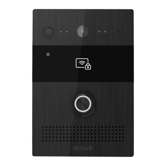
Device description AV-07T has an all-metal milled aluminum body, painted with anodizing, which emphasizes the natural beauty of the metal and creates the effect of a “live” surface. The model is presented in two colors: silver-gray and black, so it looks very stylish on different types of building facades and fits different interiors. -
Page 8: Technical Parameters
Functional capabilities Interface: WEB-interface Lock opening: By card, with the monitor AV-07T access control: Combined contactless card reader: EM-Marin and MIFARE AV-07B access control: Multiformat UKEY reader (Em-Marin, Mifare, Bluetooth, NFC) Integration with ACS: Wiegand-26, Wiegand-34 Input / Output Quick dial buttons: 1 piezoelectric ring button Number of ringtones: 1 polyphonic ringtone... - Page 9 Additional functions SIP P2P; TR-069; 2 SIP accounts; 2 relays for connection of 2 locks; 2 contacts for connection of 2 exit buttons; separate locks control; 3 controlled inputs for alarm; Motion Sensor; Gyroscope. Technical parameters – 9...
-
Page 10: Configuration Through Web Interface
“AV07T Device manager” to determine an IP address of the outdoor panel: Press the “Scan” button and program window will display IP addresses of all AV-07T outdoor panels, which are connected to the local network. It is possible to change the basic network settings, update a firmware of the outdoor panel and programmatically restart it. ... -
Page 11: Main
By default, the call panel is configured to receive network settings automatically via DHCP. To determine it on the network, you must connect the panel to a router with a DHCP server enabled. In the Internet browser, in the address entry line, you must enter the IP address of the panel, after which the user name and password entry window will appear. -
Page 12: Network Information
Network information Connection type: The current type of network connection. Connection status: The status of the network connection. LAN IP Address: device IP address. LAN subnet mask: Subnet mask. Gateway: Gateway address. DNS1: Address of the primary DNS server. DNS2: Alternate DNS server address. Account Information Account1: Registration status of the first account. -
Page 13: Push Button
Select account: Account which is used for calls. No answer call: Call forwarding function if no answer is received from dialed subscriber. Push button Push button: A field for entering a subscriber number you are dialing by pressing the ring button. -
Page 14: Advanced
Web call: Calling the number specified in the field number from the web interface of the panel. Max call time: The maximum duration of a call (2 - 30 minutes). Max dial in time: The maximum dialing time for incoming calls (from 30 to 120 seconds). Max dial out time: Maximum dialing time for outgoing calls (from 30 to 120 seconds). -
Page 15: Wiegand
Photoresistor setting: Range of sensitivity level of the photoresistor at night and day (0-100) for switching the mechanical IR filter of the camera. The default values are 5 - 37. The left value in this menu is the threshold at which the panel will switch to the “night” mode and will display the image in black and white. -
Page 16: Web Relay
Relay ID: Relay ID. Relay delay: The time by which the relay will be switched (0-10 sec.). DTMF option: The number of characters DTMF-code transmitted to trigger the relay. DTMF: Code transmitted to trigger the relay. The option is active if the item "1 character DTMF" is selected in the DTMF option. -
Page 17: Input
Switch: Enable/disable the function of opening the specified door upon receiving a special HTTP GET request. Username: User login. Password: Access password. Default values are blank. The URL format for the request is: http://192.168.1.229/fcgi/do? action=OpenDoor&UserName=admin&Password=123456&DoorNum=1, where 192.168.1.229 is the IP address of the call panel, UserName is the user name, Password is the user password, DoorNum is relay number. - Page 18 Input: Enable/disable function execution when the contacts are closed at the controlled input. Action: The action taken when closing a group of contacts. FTP: Transfer photos from the camera panel to an FTP server. Configuration through web interface – 18...
-
Page 19: Live Stream
E-mail: Transfer photos from the camera panel to the specified E-mail. SIP call: Call on SIP to the specified number in the "Action" tab number. HTTP URL: GET request to the specified address. HTTP URL: the URL to which the GET request will be sent when closing contacts. Open relay: The function of opening the specified relay when the contact group is closed. -
Page 20: Rtsp Basic
RTSP Basic RTSP Server enabled: Enabling/Disabling the RTSP server. RTSP Authorization: Enabling/Disabling authorization when you get the RTSP stream. RTSP User name: User login. RTSP Password: Access password. RTSP Stream RTSP audio: The function of sound transmitting from the outdoor panel’s microphone viathe RTSP protocol. -
Page 21: Mpeg4 Parameters
Video resolution: Resolution of the transmitted video stream (QCIF, QVGA, CIF, VGA, 4CIF, 720P). Video frame rate: Number of the transmitted frames per second (10fps, 15 fps, 20fps). Video bit rate: The compression ratio of the video stream (64 kbps, 128 kbps, 256 kbps, 512 kbps, 1024 kbps, and 2048 kbps). -
Page 22: Motion
User name: The user name to access the stream. Password: The password to access the stream. An example of an ONVIF line: http://192.168.1.186:8090/onvif/device_service. Motion Select "Motion" to access the motion sensor settings Motion detection options Motion detection: Enable/disable the motion sensor. Motion delay: The delay until the trigger when motion is detected. -
Page 23: Card Setting
Motion Sensor trigger range - 100 cm. Card setting Select “Card Setting” to access the card reader settings. Cards Import / Export (.xml) The function of creating a backup and restoring the database of stored access cards. Card status The mode of operation of the panel readers. Normal: Work in a normal card reader mode. -
Page 24: Card Setting
Adding acess cards To add access cards, you must switch the panel to the card issuing mode, click on the "obtain" button and bring the card to the reader. The field will display the card number. Further, for this card, it is necessary to choose a relay that will trigger when the card is presented, give it a name and link it to the schedule, if required. -
Page 25: Email Notification
Email notification In this menu item, the E-mail settings are specified, allowing you to send a letter to the specified address when triggered triggers are triggered in the Basic, Advanced, Inputs and Movement menus. Sender's address: E-mail of the sender of the type: ivan_petrov@yandex.ru. Recipient's address: Recipient's email address: andrey_ivanov@gmail.com. -
Page 26: Ftp Notification
FTP notification This menu item contains FTP settings that allow saving photos from the camera panel to an FTP server when triggered triggers are triggered in the Basic, Advanced, Inputs and Movement menus. FTP server: FTP server address. When specifying the FTP server address, it is necessary to specify the port number without SSL\TLS encryption (for example, 192.168.1.229:21/FTP). -
Page 27: Only Time
In this menu you can create schedules with different logics of setting time, days of week and date period. Only time Configuration through web interface – 27... -
Page 28: Only Days
Schedule name: Desired to display the name of the schedule. Date time: The time interval in hours and minutes within which this schedule will operate. Only days Configuration through web interface – 28... -
Page 29: Normal
Schedule name: Desired to display the name of the schedule. Day of week: Set exact day of week to action in this schedule. Normal Configuration through web interface – 29... -
Page 30: Account
Schedule name: Desired to display the name of the schedule. Date range: Select date range to action in this schedule. Day of week: Set exact day of week to action in this schedule. Date time: The time interval in hours and minutes within which this schedule will operate. Account Basic Select “Basic”... -
Page 31: Sip Account
SIP Account Status: Registration Status. Account: Number of the customizable account. Account Active: Enable/disable the selected account. Display Label: Account ID. Display Name: Name (Caller-ID) that is displayed for dialed subscriber. Registration Name: The account name used to register on the SIP-server. Username: The name used to register on the SIP server or proxy server. -
Page 32: Outbound Proxy Server
SIP server 2 Server IP: SIP Server address. Port: Registration port (by default is 5060). Registration period: The term of client registration on the server (by default is 1800 seconds). Outbound proxy server Proxy: Enable/disable of proxy server. Server IP: Proxy server address. Server port: Registration port of the proxy server. -
Page 33: Advanced
Advanced Select "Advanced" to access advanced settings of the SIP account: SIP Account Account: Select a customizable account. Codecs The two columns show disabled and enabled codecs. It is possible to set the required configuration using the arrow buttons and moving the codecs between the columns thereby enable and disable them. -
Page 34: Dtmf
Payload type: Profile of the RTP data. DTMF Type: Type of used DTMF (Inband, RFC2833, Info, Inband + Info, Info +RFC2833). Type of notification: Type of used event for SIP Info (Info, Inband + Info or Info + RFC2833). The item is active if DTMF, DTMF-Relay or Telephone-Event is selected. -
Page 35: Session Timer
Session Timer Active: Enable/disable timer of user registration session. Session Expire: Session Expire (90 - 7200 seconds). Session Refresher: A device that updates a session (UAC or UAS). Encryption Voice Encryption (SRTP): Voice encryption during a call. UDP Keep Alive Messages: Enabling / disabling the mode of support session. Sending Interval: The interval of sending messages about presence (5 –... -
Page 36: Advanced
DHCP: Enable automatic receiving of the network settings. Static IP Address: Enable manual mode for specifying network settings. IP address: The IP address of the outdoor panel. Subnet Mask: Subnet mask. Default Gateway: The default gateway. DNS1: The primary DNS server address. DNS2: The secondary DNS server address. - Page 37 Local RTP Starting RTP Port: The minimum value of the RTP port range (1024 –65535). Maximum RTP port: The maximum value of the RTP port range (1024 – 65535). SNMP Status: Enable/disable the SNMP device control protocol. Port: Used port (1024 – 65535). Trusted IP: List of trusted IP addresses.
-
Page 38: Phone
Status: Enable/disable of client’s TR-069. Version: Used protocol version. ACS URL: The address of ACS server. The panel will send messages about its status to this address. Username: The username for authentication on ACS. Password: The client password for authentication on ACS. Periodically Informing: Turning on / off periodic information about the status. -
Page 39: Web Language
Web language Type: Used web language Time zone: Time zone is GMT. Primary server: The address of the primary NTP server. Secondary server: The address of the additional NTP server. Update interval: Interval of updating the time (> = 3600 seconds). System time: Current system time. -
Page 40: Mode Settings
Mode: Current operating mode. Phone or custom. Mode settings Return code when refuse: The code returned by the device in case of call refusing (404 Not Found, 480 Temporary Unavailable, 486 Busy Here, 603 Decline). Auto answer delay: Delay time until the panel makes auto answer (0 - 5 seconds). Auto answer mode: The function which allows selecting the audio or video transmission during a call. -
Page 41: Microphone Volume
Microphone volume Volume: The microphone volume level (1-15). Speaker volume Speaker Volume: The speaker volume level (1 - 15). Open door warning Open door warning: Enable/disable sound when the door is opened. Open door failed warning: Enable/disable sound when you place unregistered card. Upload sound for unlock Here you can upload the audio file that will be played when the door is opened (file format: wav, size: <200KB, sampling: 16,000, Bits: 16). -
Page 42: Upload Sound For Error
Upload sound for error Sound when there is an error: The audible sound may be enabled/disabled when you place unregistered card. (file format: wav, size: <200KB, sampling: 16,000, Bits: 16). Multicast setting Multicast settings Number of listened addresses: Number of IP addresses which are listened to find out the multicast requests (Off, 1 - 10). -
Page 43: Door Log
In this tab, it is possible to make an outgoing call by pressing the corresponding number in the "Number" column. Door log Select “Door log” to access the door log history: Configuration through web interface – 43... -
Page 44: Upgrade
In this tab all access by card events are displayed. Upgrade Basic Select “Basic” to access the upgrade settings. This menu option provides information about the current version of the device. Configuration through web interface – 44... -
Page 45: Advanced
It is possible to update the device software, to reset the settings and reboot. Software update To update the panel software, you need to download and save the latest version of the software to the PC, unpack the archive with the update file, click the "Select file" button and specify the path to the software file. -
Page 46: Dhcp Option
DHCP Option Option: Change the DHCP option (128 - 254). Option 66/43 is enabled by default. Manual Configuration Receiving URL: The address of the configuration server. User name: The user name of configuration server. Password: User password. Common AES Key: AES key. AES Key (MAC): AES key (with message authentication code). -
Page 47: System Log
Hour: Hours for automatic configuration receiving (0 - 23). Min: Minute for automatic configuration receiving (0 - 59). Clear MD5: Clear MD5 hash. Export the Autop template: Export the automatic configuration template. System Log Logging level: Log level (0 - 7, where 7 is the most detailed). Export: Log export. -
Page 48: Web Password Modify
Web password modify User name: User account. Current Password: The current user password. New password: New user password. Confirm Password: Repeat the new user password. Session timeout Session timeout: The session timeout in the browser (60 - 14400 seconds). Configuration through web interface – 48... -
Page 49: Installation And Connection
Installation and connection This page describes the process of installing and connecting the panel. • Product completeness check (see page 49) • Electrical connection (see page 49) • Mechanical mounting (see page 52) • Connection of additional modules (see page 63) Product completeness check Before installing the call panel, be sure to check its completeness and the presence of all components. - Page 50 When connecting the panel panel by PoE,it is prohibited to power the lock using panel's power. You must use a separate power supply, otherwise it may cause damage to the device. • Power supply at +12 Volt, 2 Ampere. • Wires must be brought for connecting the lock and additional modules (optional).
- Page 51 Installation and connection – 51...
-
Page 52: Mechanical Mounting
Pin assignment on the outdoor panel: GND: Ground. 12V: Power supply + 12 Volts. 485A: RS485 Data +. 485B: RS485 Data -. DoorA-DoorE: Controlled inputs (dry contacts). It is possible to use for connecting the exit buttons and door sensors, and fire alarm sensors as well, if connected to the corresponding bus. GNDA-GNDE: Ground for controlled inputs. - Page 53 2. Attach the wall-mounting bracket to wall and make marks exactly where the holes need to be drilled. 3. Make holes using an electric drill according to the made marks. Use drill bit with a diameter of not more than 5 mm. Installation and connection – ...
- Page 54 4. Insert the dowels in previously made holes and hammer them. 5. Fix a wall-mounting bracket into the wall, using ST4X20 screws. Installation and connection – 54...
- Page 55 6. Install a protective cover and sealing ring as shown in figure. 7. Make a connection of all wires and connect the sealing ring with protective shroud as shown in figure. Installation and connection – 55...
- Page 56 8. Install the protective cover with M3X5 screws as shown in figure. Installation and connection – 56...
-
Page 57: Flush Mounting
9. Install the panel in the bracket for the wall mounting and fix it using M2.5X6.5 screws. 10. Installation completed. Flush mounting Installation and connection – 57... - Page 58 1. Make a hole in the wall of the following sizes 163.8 x 110.1 x 65 mm. It will serve for placing of bracket for flush mounting and all cable connections. 2. Install the bracket into ready hole and make marks for subsequent bracket mounting. 3.
- Page 59 4. Insert the dowels in previously made holes and hammer them. 5. Fix the flush-mounting bracket into the wall, using the ST4x20 screws. Installation and connection – 59...
- Page 60 6. To achieve maximum fixation, it is necessary to seal the gap between the wall and bracket using cement or other, not aggressive to metal mixture. 7. Insert the built-in box into the bracket and fix it using M4X10 screws. Installation and connection – ...
- Page 61 8. Install a protective cover and sealing ring as shown in figure. 9. Make a connection of all wires and connect the sealing ring with protective shroud as shown in figure. Installation and connection – 61...
- Page 62 10. Install the protective cover with M3X5 screws as shown in figure. 11. Install the panel in place and fix it with M2.5X6.5 screws using Allen key as shown in figure. Installation and connection – 62...
-
Page 63: Connection Of Additional Modules
12. Installation completed. Connection of additional modules You can connect following modues to this panel: • Two locks control module SH-42 • The multiformat reader with support of the UKEY technology BME-03 • 2 "Exit" buttons Installation and connection – 63... - Page 64 • 2 Door sensors • 1 Fire alarm Installation and connection – 64...
-
Page 65: Usage Of The Device
UKEY mobile access Description Ukey Mobile Access from BAS-IP is a universal technology for gaining access to the premises or to the territory of an object with the possibility to use in one reader simultaneously: EM-Marin cards and MIFARE/encrypted cards MIFARE Plus/MIFARE Classic, cell phone (Bluetooth and NFC). -
Page 66: Ukey+Cfg Application
For users' ease of operation with BAS-IP outdoor panels equipped with multi-format readers, the company BAS-IP has released a new mobile Ukey application which, after receiving the mobile ID, is used to open the doors/gates/parking gate arms. For each outdoor panel equipped with a reader module with support for UKEY Mobile access, a different range of the mobile ID can be configured, in the range of 2 centimeters to 10 meters. - Page 67 You cannot copy or duplicate an identifier. Using BAS-IP TR-03B reader In order for the administrator of the management company to be able to use TR-03B to issue mobile identifiers or to record access cards, it is necessary to specify the master-card, ...
- Page 68 5. Bring a cell phone to the reader (make sure Bluetooth is on) and enter UKEY App, then press Obtain button or select Obtain BAS-IP TR-03 key. 6. The reader will transmit a mobile ID to your cell phone, thus "Your key is ready" will appear in the app.
-
Page 69: List Of Commands For Panel Control Using Tr-069 Protocol
List of commands for panel control using TR-069 protocol Device.DeviceInfo.Manufacture Device.DeviceInfo.ManufacturerOUI Device.DeviceInfo.ModelName Device.DeviceInfo.SoftwareVersion Device.DeviceInfo.ProductClass Device.DeviceInfo.SerialNumber Device.DeviceInfo.HardwareVersion Device.DeviceInfo.UpTime Device.DeviceInfo.ProvisioningCode Device.ManagementServer.URL Device.ManagementServer.Username Device.ManagementServer.Password Device.ManagementServer.PeriodicInformEnable Device.ManagementServer.PeriodicInformInterval Device.ManagementServer.PeriodicInformTime Device.ManagementServer.ParameterKey Device.ManagementServer.ConnectionRequestURL Device.ManagementServer.ConnectionRequestUsername Usage of the device – 69... - Page 70 Device.ManagementServer.ConnectionRequestPassword Device.ManagementServer.STUNEnable Device.ManagementServer.STUNServerAddress Device.ManagementServer.STUNServerPort Device.ManagementServer.STUNUsername Device.ManagementServer.STUNPassword Device.ManagementServer.STUNMaximumKeepAlivePeriod Device.ManagementServer.STUNMinimumKeepAlivePeriod Device.ManagementServer.NATDetected Device.ManagementServer.UDPConnectionRequestAddress Device.ManagementServer.UDPConnectionRequestAddressNotificationLimit Device.ManagementServer.UpgradesManaged Device.Time.NTPServer1 Device.Time.NTPServer2 Device.Time.LocalTimeZone Device.UserInterface.CUSTOM_Preference.CUSTOM_LanguageType Device.UserInterface.CUSTOM_Preference.CUSTOM_BackLight Device.UserInterface.CUSTOM_Preference.CUSTOM_BacklightTime Device.UserInterface.CUSTOM_Preference.CUSTOM_HandfreeSpkVol Device.UserInterface.CUSTOM_Preference.CUSTOM_HandfreeMicVol Device.UserInterface.CUSTOM_Preference.CUSTOM_HandsetSpkVol Device.UserInterface.CUSTOM_Preference.CUSTOM_HandsetMicVol Device.UserInterface.CUSTOM_Preference.CUSTOM_HeadsetSpkVol Device.UserInterface.CUSTOM_Preference.CUSTOM_HeadsetMicVol Device.UserInterface.CUSTOM_Preference.CUSTOM_RingVol Device.UserInterface.CUSTOM_Preference.CUSTOM_HeadsetToneVol Device.UserInterface.CUSTOM_Preference.CUSTOM_HandsetToneVol Device.UserInterface.CUSTOM_Preference.CUSTOM_HandfreeToneVol Device.UserInterface.CUSTOM_Features.CUSTOM_CallWaiting Device.UserInterface.CUSTOM_Features.CUSTOM_HotlineNumber Device.UserInterface.CUSTOM_Features.CUSTOM_DNDEnable Device.UserInterface.CUSTOM_Features.CUSTOM_DNDOnCode Device.UserInterface.CUSTOM_Features.CUSTOM_DNDOffCode Device.UserInterface.CUSTOM_Features.CUSTOM_AlwaysForwardEnable Device.UserInterface.CUSTOM_Features.CUSTOM_AlwaysForwardTarget Usage of the device – 70...
- Page 71 Device.UserInterface.CUSTOM_Features.CUSTOM_AlwaysForwardOnCode Device.UserInterface.CUSTOM_Features.CUSTOM_AlwaysForwardOffCode Device.UserInterface.CUSTOM_Features.CUSTOM_BusyForwardEnable Device.UserInterface.CUSTOM_Features.CUSTOM_BusyForwardTarget Device.UserInterface.CUSTOM_Features.CUSTOM_BusyForwardOnCode Device.UserInterface.CUSTOM_Features.CUSTOM_BusyForwardOffCode Device.UserInterface.CUSTOM_Features.CUSTOM_TimeoutForwardEnable Device.UserInterface.CUSTOM_Features.CUSTOM_TimeoutForwardTarget Device.UserInterface.CUSTOM_Features.CUSTOM_TimeoutForwardTimeout Device.UserInterface.CUSTOM_Features.CUSTOM_TimeoutForwardOnCode Device.UserInterface.CUSTOM_Features.CUSTOM_TimeoutForwardOffCode Device.UserInterface.CUSTOM_DialPlan.CUSTOM_AreaCode Device.UserInterface.CUSTOM_DialPlan.CUSTOM_AreaCodeMinLen Device.UserInterface.CUSTOM_DialPlan.CUSTOM_AreaCodeMaxLen Device.UserInterface.CUSTOM_Voice.CUSTOM_VAD Device.UserInterface.CUSTOM_Voice.CUSTOM_JitterBufferAdaptive Device.UserInterface.CUSTOM_Voice.CUSTOM_JitterBufferMin Device.UserInterface.CUSTOM_Voice.CUSTOM_JitterBufferMax Device.UserInterface.CUSTOM_Voice.CUSTOM_JitterBufferNominal Device.UserInterface.CUSTOM_Update.CUSTOM_PNP Device.UserInterface.CUSTOM_Update.CUSTOM_DHCPOption Device.UserInterface.CUSTOM_Update.CUSTOM_ServerUrl Device.UserInterface.CUSTOM_Update.CUSTOM_AutoProvisionMode Device.UserInterface.CUSTOM_Update.CUSTOM_AutoProvisionScheduleTime Device.UserInterface.CUSTOM_Update.CUSTOM_AutoProvisionScheduleDayOfWeek Device.UserInterface.CUSTOM_RemotePhoneBook.CUSTOM_PhoneBook0URL Device.UserInterface.CUSTOM_RemotePhoneBook.CUSTOM_PhoneBook0Name Device.UserInterface.CUSTOM_RemotePhoneBook.CUSTOM_PhoneBook1URL Device.UserInterface.CUSTOM_RemotePhoneBook.CUSTOM_PhoneBook1Name Device.UserInterface.CUSTOM_RemotePhoneBook.CUSTOM_PhoneBook2URL Device.UserInterface.CUSTOM_RemotePhoneBook.CUSTOM_PhoneBook2Name Device.UserInterface.CUSTOM_RemotePhoneBook.CUSTOM_PhoneBook3URL Device.UserInterface.CUSTOM_RemotePhoneBook.CUSTOM_PhoneBook3Name Device.UserInterface.CUSTOM_RemotePhoneBook.CUSTOM_PhoneBook4URL Device.UserInterface.CUSTOM_RemotePhoneBook.CUSTOM_PhoneBook4Name Usage of the device – 71...
- Page 72 Device.LAN.AddressingType Device.LAN.IPAddress Device.LAN.SubnetMask Device.LAN.DefaultGateway Device.LAN.DNSServer Device.LAN.DNSServers2 Device.LAN.MACAddress Device.LAN.MACAddressOverride Device.LAN.VoiceService.1.VoiceProfileNumberOfEntries Device.LAN.VoiceService.1.Capabilities.MaxProfileCount Device.LAN.VoiceService.1.Capabilities.MaxLineCount Device.LAN.VoiceService.1.Capabilities.SignalingProtocols Device.LAN.VoiceService.1.Capabilities.RTCP Device.LAN.VoiceService.1.Capabilities.SRTPKeyingMethod Device.LAN.VoiceService.1.Capabilities.RTPRedundancy Device.LAN.VoiceService.1.Capabilities.DSCPCoupled Device.LAN.VoiceService.1.Capabilities.EthernetTaggingCoupled Device.LAN.VoiceService.1.Capabilities.PSTNSoftSwitchOver Device.LAN.VoiceService.1.Capabilities.FaxT38 Device.LAN.VoiceService.1.Capabilities.FaxPassThrough Device.LAN.VoiceService.1.Capabilities.ToneGeneration Device.LAN.VoiceService.1.Capabilities.ToneDescriptionsEditable Device.LAN.VoiceService.1.Capabilities.PatternBasedToneGeneration Device.LAN.VoiceService.1.Capabilities.FileBasedToneGeneration Device.LAN.VoiceService.1.Capabilities.RingGeneration Device.LAN.VoiceService.1.Capabilities.RingDescriptionsEditable Device.LAN.VoiceService.1.Capabilities.PatternBasedRingGeneration Device.LAN.VoiceService.1.Capabilities.RingPatternEditable Device.LAN.VoiceService.1.Capabilities.FileBasedRingGeneration Device.LAN.VoiceService.1.Capabilities.DigitMap Device.LAN.VoiceService.1.Capabilities.NumberingPlan Device.LAN.VoiceService.1.Capabilities.ButtonMap Device.LAN.VoiceService.1.Capabilities.SRTP Device.LAN.VoiceService.1.Capabilities.SIP.Role Device.LAN.VoiceService.1.Capabilities.SIP.Extensions Usage of the device – 72...
- Page 73 Device.LAN.VoiceService.1.Capabilities.SIP.Transports Device.LAN.VoiceService.1.Capabilities.SIP.URISchemes Device.LAN.VoiceService.1.Capabilities.SIP.EventSubscription Device.LAN.VoiceService.1.Capabilities.SIP.Codecs.{1}.EntryID Device.LAN.VoiceService.1.Capabilities.SIP.Codecs.{1}.Codec Device.LAN.VoiceService.1.Capabilities.SIP.Codecs.{1}.BitRate Device.LAN.VoiceService.1.Capabilities.SIP.Codecs.{1}.PacketizationPeriod Device.LAN.VoiceService.1.Capabilities.SIP.Codecs.{1}.SilenceSuppression Device.LAN.VoiceService.1.Capabilities.SIP.Codecs.{2}.EntryID Device.LAN.VoiceService.1.Capabilities.SIP.Codecs.{2}.Codec Device.LAN.VoiceService.1.Capabilities.SIP.Codecs.{2}.BitRate Device.LAN.VoiceService.1.Capabilities.SIP.Codecs.{2}.PacketizationPeriod Device.LAN.VoiceService.1.Capabilities.SIP.Codecs.{2}.SilenceSuppression Device.LAN.VoiceService.1.Capabilities.SIP.Codecs.{3}.EntryID Device.LAN.VoiceService.1.Capabilities.SIP.Codecs.{3}.Codec Device.LAN.VoiceService.1.Capabilities.SIP.Codecs.{3}.BitRate Device.LAN.VoiceService.1.Capabilities.SIP.Codecs.{3}.PacketizationPeriod Device.LAN.VoiceService.1.Capabilities.SIP.Codecs.{3}.SilenceSuppression Device.LAN.VoiceService.1.Capabilities.SIP.Codecs.{4}.EntryID Device.LAN.VoiceService.1.Capabilities.SIP.Codecs.{4}.Codec Device.LAN.VoiceService.1.Capabilities.SIP.Codecs.{4}.BitRate Device.LAN.VoiceService.1.Capabilities.SIP.Codecs.{4}.PacketizationPeriod Device.LAN.VoiceService.1.Capabilities.SIP.Codecs.{4}.SilenceSuppression Device.LAN.VoiceService.1.Capabilities.SIP.Codecs.{5}.EntryID Device.LAN.VoiceService.1.Capabilities.SIP.Codecs.{5}.Codec Device.LAN.VoiceService.1.Capabilities.SIP.Codecs.{5}.BitRate Device.LAN.VoiceService.1.Capabilities.SIP.Codecs.{5}.PacketizationPeriod Device.LAN.VoiceService.1.Capabilities.SIP.Codecs.{5}.SilenceSuppression Device.LAN.VoiceService.1.Capabilities.SIP.Codecs.{6}.EntryID Device.LAN.VoiceService.1.Capabilities.SIP.Codecs.{6}.Codec Device.LAN.VoiceService.1.Capabilities.SIP.Codecs.{6}.BitRate Device.LAN.VoiceService.1.Capabilities.SIP.Codecs.{6}.PacketizationPeriod Device.LAN.VoiceService.1.Capabilities.SIP.Codecs.{6}.SilenceSuppression Device.LAN.VoiceService.1.Capabilities.SIP.Codecs.{7}.EntryID Device.LAN.VoiceService.1.Capabilities.SIP.Codecs.{7}.Codec Usage of the device – 73...
- Page 74 Device.LAN.VoiceService.1.Capabilities.SIP.Codecs.{7}.BitRate Device.LAN.VoiceService.1.Capabilities.SIP.Codecs.{7}.PacketizationPeriod Device.LAN.VoiceService.1.Capabilities.SIP.Codecs.{7}.SilenceSuppression Device.LAN.VoiceService.1.Capabilities.SIP.Codecs.{8}.EntryID Device.LAN.VoiceService.1.Capabilities.SIP.Codecs.{8}.Codec Device.LAN.VoiceService.1.Capabilities.SIP.Codecs.{8}.BitRate Device.LAN.VoiceService.1.Capabilities.SIP.Codecs.{8}.PacketizationPeriod Device.LAN.VoiceService.1.Capabilities.SIP.Codecs.{8}.SilenceSuppression Device.LAN.VoiceService.1.Capabilities.SIP.Codecs.{9}.EntryID Device.LAN.VoiceService.1.Capabilities.SIP.Codecs.{9}.Codec Device.LAN.VoiceService.1.Capabilities.SIP.Codecs.{9}.BitRate Device.LAN.VoiceService.1.Capabilities.SIP.Codecs.{9}.PacketizationPeriod Device.LAN.VoiceService.1.Capabilities.SIP.Codecs.{9}.SilenceSuppression Device.LAN.VoiceService.1.Capabilities.SIP.Codecs.{10}.EntryID Device.LAN.VoiceService.1.Capabilities.SIP.Codecs.{10}.Codec Device.LAN.VoiceService.1.Capabilities.SIP.Codecs.{10}.BitRate Device.LAN.VoiceService.1.Capabilities.SIP.Codecs.{10}.PacketizationPeriod Device.LAN.VoiceService.1.Capabilities.SIP.Codecs.{10}.SilenceSuppression Device.LAN.VoiceService.1.VoiceProfile.{i}.Reset Device.LAN.VoiceService.1.VoiceProfile.{i}.SignalingProtocol Device.LAN.VoiceService.1.VoiceProfile.{i}.MaxSessions Device.LAN.VoiceService.1.VoiceProfile.{i}.DTMFMethod Device.LAN.VoiceService.1.VoiceProfile.{i}.STUNEnable Device.LAN.VoiceService.1.VoiceProfile.{i}.STUNServer Device.LAN.VoiceService.1.VoiceProfile.{i}.SIP.RegistrarServer Device.LAN.VoiceService.1.VoiceProfile.{i}.SIP.OutboundProxy Device.LAN.VoiceService.1.VoiceProfile.{i}.SIP.OutboundProxyPort Device.LAN.VoiceService.1.VoiceProfile.{i}.SIP.ProxyServer Device.LAN.VoiceService.1.VoiceProfile.{i}.SIP.ProxyServerPort Device.LAN.VoiceService.1.VoiceProfile.{i}.SIP.UserAgentDomain Device.LAN.VoiceService.1.VoiceProfile.{i}.SIP.UserAgentPort Device.LAN.VoiceService.1.VoiceProfile.{i}.SIP.RegisterExpires Device.LAN.VoiceService.1.VoiceProfile.{i}.SIP.ExpireTime Device.LAN.VoiceService.1.VoiceProfile.{i}.RTP.TelephoneEventPayloadType Device.LAN.VoiceService.1.VoiceProfile.{i}.Line.1.Enable Usage of the device – 74...
- Page 75 Device.LAN.VoiceService.1.VoiceProfile.{i}.Line.1.Status Device.LAN.VoiceService.1.VoiceProfile.{i}.Line.1.RingMuteStatus Device.LAN.VoiceService.1.VoiceProfile.{i}.Line.1.RingVolumeStatus Device.LAN.VoiceService.1.VoiceProfile.{i}.Line.1.SIP.AuthUserName Device.LAN.VoiceService.1.VoiceProfile.{i}.Line.1.SIP.AuthPassword Device.LAN.VoiceService.1.VoiceProfile.{i}.Line.1.SIP.CUSTOM_Label Device.LAN.VoiceService.1.VoiceProfile.{i}.Line.1.SIP.CUSTOM_UserName Device.LAN.VoiceService.1.VoiceProfile.{i}.Line.1.SIP.CUSTOM_DisplayName Device.LAN.VoiceService.1.VoiceProfile.{i}.Line.1.Codec.List.{i}.Codec Device.LAN.VoiceService.1.VoiceProfile.{i}.Line.1.Codec.List.{i}.Priority Device.LAN.VoiceService.1.VoiceProfile.{i}.Line.1.Codec.List.{i}.Enable Usage of the device – 75...
Need help?
Do you have a question about the AV-07T and is the answer not in the manual?
Questions and answers