AUTEC Dynamic Series Original Instructions Manual
Receiving unit
Hide thumbs
Also See for Dynamic Series:
- User manual (36 pages) ,
- Instruction manual for the use and the maintenance (20 pages) ,
- Original instructions manual (8 pages)
Table of Contents
Advertisement
Original instructions
DYNAMIC SERIES
1
Description ............................................................................................................ 2
1.1 Safety functions of the ARX receiving unit ....................................................... 3
2
Technical data ....................................................................................................... 3
3
Technical data sheet ............................................................................................. 3
4
Plates ..................................................................................................................... 4
5
Light signals .......................................................................................................... 4
5.1 POWER LED (green) ....................................................................................... 4
5.2 ALARM LED (red) ............................................................................................ 5
5.3 STATUS LED (blue) ......................................................................................... 5
5.4 SETUP LED (yellow) ........................................................................................ 5
6
Values of proportional outputs ............................................................................ 6
6.1 Calibrating maximum and minimum values of proportional outputs .................. 7
6.3 Inversion of movement direction of the joystick's axis ...................................... 8
6.4 Restoring factory settings ................................................................................ 9
7
Malfunction signalled by the receiving unit ...................................................... 10
AUTEC
Part D: ARX receiving unit
INDEX
LIARXE00-00
Advertisement
Table of Contents

Related Manuals for AUTEC Dynamic Series


Summary of Contents for AUTEC Dynamic Series
-
Page 1: Table Of Contents
Original instructions DYNAMIC SERIES Part D: ARX receiving unit INDEX Description ......................2 1.1 Safety functions of the ARX receiving unit ............3 Technical data ....................... 3 Technical data sheet ..................... 3 Plates ........................4 Light signals ......................4 5.1 POWER LED (green) ..................4 5.2 ALARM LED (red) .................... -
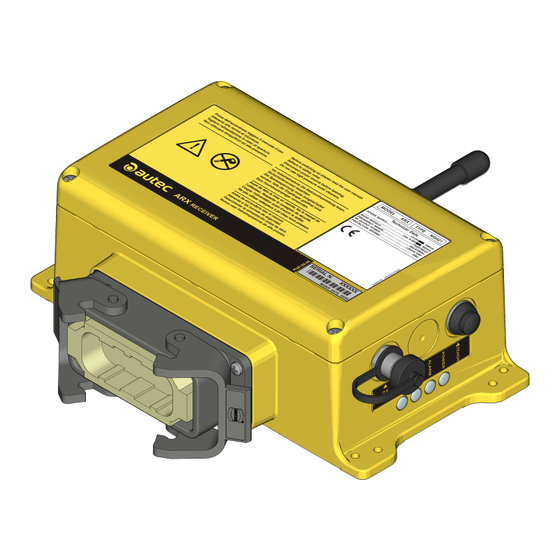
Page 2: Description
Nunca usar hidrolimpiadoras de alta presión. SERIAL N. XXXXXX MANIF. DATE XXXX LEDs plug antenna DTK connector (for memory board) mounting holes IDK (for address key) TEACH pushbutton fuse F1 connector for cable control DIP switches LIARXE00-00 AUTEC - Dynamic Series... -
Page 3: Safety Functions Of The Arx Receiving Unit
A copy of the technical data sheet must always be kept together with this manual (always keep a copy of this data sheet for administrative purposes). The wiring of the receiving unit outputs must always reflect the wiring indicated in the technical data sheet. AUTEC - Dynamic Series LIARXE00-00... -
Page 4: Plates
Meaning …is off The receiving unit is switched off..is on The receiving unit is powered and there is no radio link. The receiving unit is powered and radio link has been … blinks built. LIARXE00-00 AUTEC - Dynamic Series... -
Page 5: Alarm Led (Red)
The SETUP LED shows the status of the data memory and of the address key, depending on the receiving unit's working status. The SETUP LED... Meaning …is off The receiving unit works correctly..blinks once Error on the address key..blinks twice Error on the memory board. AUTEC - Dynamic Series LIARXE00-00... -
Page 6: Values Of Proportional Outputs
The REMOTE SETUP procedure can only be performed by skilled and properly trained personnel. During the REMOTE SETUP procedure, pay particular attention to the machine behaviour, as it moves as a response to acting on the actuators. LIARXE00-00 AUTEC - Dynamic Series... -
Page 7: Calibrating Maximum And Minimum Values Of Proportional Outputs
If a speed selector is present on the transmitting unit, minimum and maximum values have to be calibrated for each of the selector positions. If inputs are used in the receiving unit to select different speeds, calibration must be performed for any possible configuration of the inputs. AUTEC - Dynamic Series LIARXE00-00... -
Page 8: Calibrating Values Related To The Rest Position Of Proportional Outputs (Offset)
6. To invert other directions, unlock the STOP pushbutton, press the START pushbutton and repeat actions described in the previous point. 7. To leave the procedure, press the TEACH pushbutton on the receiving unit and do not release it until the SETUP LED switches off. LIARXE00-00 AUTEC - Dynamic Series... -
Page 9: Restoring Factory Settings
TEACH pushbutton is released before the SETUP LED is steadily illuminated, factory settings of proportional outputs will not be restored. 6. To leave the procedure, press the TEACH pushbutton on the receiving unit and do not release it until the SETUP LED switches off. AUTEC - Dynamic Series LIARXE00-00... -
Page 10: Malfunction Signalled By The Receiving Unit
Make sure that the DIP switches are set Configuration erroron the as on the technical data sheet. The ALARM LED is on. SO1 and SO2 outputs. If this signal persists, contact the support service of the machine manufacturer. LIARXE00-00 AUTEC - Dynamic Series... - Page 11 Two or more analogue commands are being Check actuators on the transmitting The SETUP LED blinks activated simultaneously unit and activate one single analogue quickly. within the REMOTE command. SETUP procedure. AUTEC - Dynamic Series LIARXE00-00...
Need help?
Do you have a question about the Dynamic Series and is the answer not in the manual?
Questions and answers
Hello, how is programming done