Table of Contents
Advertisement
Your new tool has been engineered and manufactured to WEN's highest standards for dependability,
ease of operation, and operator safety. When properly cared for, this product will supply you years
of rugged, trouble-free performance. Pay close attention to the rules for safe operation, warnings,
and cautions. If you use your tool properly and for intended purpose, you will enjoy years of safe,
reliable service.
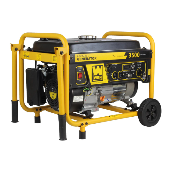
3500W PORTABLE
IMPORTANT:
NEED HELP? CONTACT US!
Have product questions? Need technical support?
Please feel free to contact us at:
800-232-1195
techsupport@wenproducts.com
WENPRODUCTS.COM
GENERATOR
(M-F 8AM-5PM CST)
Model # 56352
bit.ly/WENvideo
Advertisement
Table of Contents

Related Manuals for Wen 56352


Summary of Contents for Wen 56352
- Page 1 IMPORTANT: Your new tool has been engineered and manufactured to WEN’s highest standards for dependability, ease of operation, and operator safety. When properly cared for, this product will supply you years of rugged, trouble-free performance. Pay close attention to the rules for safe operation, warnings, and cautions.
-
Page 2: Table Of Contents
TABLE OF CONTENTS Generator Identification Service Record Introduction Safety Information Know Your Generator Assembly Generator Preperation Starting the Generator Stopping the Generator Subsequent Starting of the Generator Using the Generator Maintenance & Care Storage & Transport Specifications Troubleshooting Exploded View and Parts List Wiring Diagram Warranty Statement... -
Page 3: Generator Identification
GENERATOR IDENTIFICATION If assistance for information or service is required, please contact the Customer Service Help Line by calling 800-232-1195; customer will be asked to provide generator information when calling. Refer to the illustration below for the location of the serial number. Record generator information in the spaces provided below. -
Page 4: Introduction
Every effort has been made to ensure the accuracy of the information in this manu- al. WEN reserves the right to change this product, manual and specifications at any time without prior notice. Please keep this manual available to all users during the entire life of the generator. - Page 5 SAFETY INFORMATION For any questions regarding the hazard and safety notices listed in this manual or on the product, please call (800) 232-1195 M-F 8-5 CST before using the generator. DANGER: CARBON MONOXIDE Using a generator indoors CAN KILL YOU IN MINUTES. Generator exhaust contains carbon monox- ide (CO).
- Page 6 150 F (65 SAVE THESE INSTRUCTIONS – This manual contains important instructions for the WEN generator that should be followed during installation and maintenance of the generator. Generators vibrate in normal use. During and after the use of the generator, inspect both the generator as well as extension and power supply cords for damage resulting from vibration.
-
Page 7: Know Your Generator
KNOW YOUR GENERATOR Use the illustrations below to become familiar with the locations and functions of the various components and controls of this generator. Fuel Gauge Voltage Selector Fuel Cap 120V AC Duplex 12V Cigarette Lighter Style DC Receptacle Receptacle Oil Fill and Dipstick Power Indicators (3 total) Engine Switch... -
Page 8: Assembly
ASSEMBLY For video instructions visit bit.ly/WHEELKIT First, check to make sure your wheel kit includes all of the necessary parts. Each item comes pre-assembled with the necessary nuts and washers already attached to the proper bolts. INCLUDED: A) Two Wheels B) Two Handles (each equipped with one washer and one bolt) C) Two Support Legs (each equipped... - Page 9 ASSEMBLY 5) Once both wheels are installed, attach the support legs to the generator as shown in Figure B. Again, remove the bolts, slide the legs into place and align the two holes. 6) Reattach the bolts using the 10/13 and the 10/12 mm wrenches.
-
Page 10: Generator Preperation
GENERATOR PREPARATION USING THE GENERATOR FOR THE FIRST TIME CAUTION: The following section describes the necessary steps to prepare the generator for use. If after reading this section, you are unsure about how to perform any of the steps please call (800) 232-1195 M-F 8-5 CST for customer service. - Page 11 GENERATOR PREPARATION WARNING: This generator may emit highly flammable and explosive gasoline vapors, which can cause severe burns or even death if ignited. A nearby open flame can lead to explosion even if not directly in contact with gasoline. Step 2 - ADD GASOLINE IMPORTANT: •...
-
Page 12: Starting The Generator
STARTING THE GENERATOR Before starting the generator, make sure you have read and performed the steps in the “Generator Preparation” section of this manual. If you are unsure about how to perform any of the steps in this manual please call (800) 232-1195 M-F 8-5 CST for customer service. -
Page 13: Stopping The Generator
STARTING THE GENERATOR STARTING THE ENGINE To start the generator, perform the following steps: 1. Unplug all electrical devices from the generator during ignition. Other- wise it will be difficult for the engine to start. 2. Check that the generator is properly grounded (page 11). 3. -
Page 14: Subsequent Starting Of The Generator
SUBSEQUENT STARTING OF THE GENERATOR If this is not the first time using the generator, the user should take the following steps to prepare it for operation. IMPORTANT: At this point the user should be familiar with the procedures described in the sections titled “Starting the Generator”... -
Page 15: Using The Generator
The surge wattage ability of the generator covers this extra power requirement. Item Rated (Running) Wattage Surge Wattage 56352 3000 3500 Fig. 6 - Generator Wattage The total running wattage requirement of the electrical devices connected to the generator should not exceed the rated wattage of the generator itself. - Page 16 USING THE GENERATOR CAUTION: The generator can run at its surge wattage capacity for only a short time. Connect electrical devices requiring a rated (running) wattage equal to or less than the rated wattage of the generator. Never connect devices requiring a rated wattage equal to the surge wattage of the generator.
- Page 17 USING THE GENERATOR CAUTION: Do not connect 50Hz loads to the generator. SOME NOTES ABOUT POWER CORDS Long or thin cords can drain the power provided to an electrical device by the generator. When using such cords, allow for a slightly higher rated wattage requirement by the electrical device. Device Requirements Max.
-
Page 18: Maintenance & Care
MAINTENANCE Proper routine maintenance of the generator will help prolong the life of the machine. Please perform mainte- nance checks according to the schedule in Fig. 9. If there are any questions about the maintenance procedures listed in this manual, please call (800) 232-1195 M-F 8-5CT. CAUTION: Never perform maintenance operations while the generator is running. - Page 19 MAINTENANCE HIGH ALTITUDE OPERATION ABOVE 3000 FEET The fuel system on this generator may be affected by operation at high altitudes. Proper operation can be ensured by installing an altitude kit at altitudes higher than 3000 feet above sea level. At elevations above 8000 feet, the engine may experience a decrease in performance, even with the proper altitude kit.
- Page 20 MAINTENANCE CHANGING/DRAINING THE OIL Change the oil according to the Recommended Maintenance Schedule in Fig. 9. Changing the oil when the engine is warm allows for complete drainage. Change the oil more often if operating under heavy load or high ambient temperatures.
- Page 21 MAINTENANCE AIR CLEANER MAINTENANCE Routine maintenance of the air cleaner helps maintain Cover proper airflow to the carburetor. Occasionally check that Bolt the air cleaner is free of excessive dirt. Refer to Recom- mended Maintenance Schedule in Fig. 9. For air cleaner detail, refer to Fig.
- Page 22 MAINTENANCE SPARK PLUG MAINTENANCE Check the spark plug regularly for proper engine operation (refer to the Recommended Maintenance Schedule in Fig. 9). A good spark plug should be intact, free of deposits, and properly gapped. To inspect the spark plug: 1.
-
Page 23: Storage & Transport
STORAGE & TRANSPORT DRAINING THE FUEL TANK Clean the fuel tank each year or before storing the generator for extended periods of time. To drain the fuel tank and carburetor: 1. Turn the fuel valve to the “OFF” position. 2. Remove the fuel line between the fuel valve and carburetor. CAUTION: A small amount of fuel may leak from the hose during removal. -
Page 24: Specifications
STORAGE & TRANSPORT CAUTION: Never place any type of storage cover on the generator while it is still hot. If the generator is being stored for short periods of time (30 to 60 days), add stabilized fuel to the fuel tank until full. -
Page 25: Troubleshooting
TROUBLESHOOTING IMPORTANT: If trouble persists, please call our customer help line at (800) 232-1195 M-F 8-5 Central Time. PROBLEM CAUSE SOLUTION Engine switch is set to Set engine switch to “ON.” “OFF.” Fuel valve is turned to Turn the fuel valve to the “ON” “OFF.”... -
Page 26: Exploded View And Parts List
EXPLODED VIEW AND PARTS LIST Fig. 1 - Cylinder Head Assembly Part Description Qty. Fig. 1-4 P54051 Cylinder Head Gasket Fig. 1-5 Cylinder Head Cover Assembly P54066 Fig. 2 - Crankcase Assembly Fig. 1-6 P54064 Cylinder Head Cover Gasket Part Description Qty. - Page 27 EXPLODED VIEW AND PARTS LIST Fig. 5 - Piston Ring/Connecting Rod Part Description Qty. Fig. 5-1 P54105 Piston Ring Assembly Fig. 7 - Recoil Starter Fig. 5-2 P54106 Piston Pin Clip Part Description Qty. Fig. 5-3 P54109 Piston Fig. 7-11 P54604 Recoil Starter Assembly Fig.
- Page 28 EXPLODED VIEW AND PARTS LIST Fig. 11 - Flywheel/Ignition Coil Part Description Qty. Fig. 11-1 P54630 Nut M14 X 1.5 Fig. 11-2 P54362 Starting Flange Fig. 9 - Carburetor Assembly Fig. 11-3 P54634 Flywheel Fan Part Description Qty. Fig. 11-4 P54636 Flywheel Fig.
- Page 29 EXPLODED VIEW AND PARTS LIST Fig. 13 - Muffler Assembly Part Description Qty. Muffler Assembly Fig. 13-1 P54401 Fig. 14 - Tank, Fuel Cover, Outer Muffler Fig. 13-2 P54402 Part Description Qty. P54412 Bracket, Muffler Fig. 13-3 P54371 Fuel Tank F14-1 P54422 Bolt...
- Page 30 Fig. 16-8 P54838 Circuit Breaker Fig. 17-11 P54337 End Cover Fig. 16-9 P54272 120/240V Receptacle Fig. 17-12 P54340 Bolt Fig. 16-11 56352-1611 Wiring Harness Fig. 17-13 56475-1913 Stopper Fig. 16-12 56352-1612 Rear Panel Fig. 17-14 P54340 Bolt Fig. 16-13 P54304 Bolt Fig.
- Page 31 EXPLODED VIEW AND PARTS LIST Fig. 18 - Wheel Kit Assembly Part Description Qty. P54872-1 Wheel Fig. 18-1 P54879 Wheel Shaft Fig. 18-2 P54872-5 Fig. 18-3 P54872-3 Washer Fig. 18-4 56400-1805 Washer Fig. 18-5 Fig. 19 - Handles Part Description Qty.
-
Page 32: Wiring Diagram
WIRING DIAGRAM... -
Page 33: Warranty Statement
WEN® will repair or replace, at its discretion, any part that is proven to be defective in materials or workman- ship under normal use during the two (2) years warranty period. Warranty repairs or replacements will be made without charge for parts or labor. - Page 34 THANKS FOR REMEMBERING...
Need help?
Do you have a question about the 56352 and is the answer not in the manual?
Questions and answers