Table of Contents
Advertisement
Quick Links
Your new tool has been engineered and manufactured to WEN's highest standards for dependability,
ease of operation, and operator safety. When properly cared for, this product will supply you years
of rugged, trouble-free performance. Pay close attention to the rules for safe operation, warnings,
and cautions. If you use your tool properly and for intended purpose, you will enjoy years of safe,
reliable service.
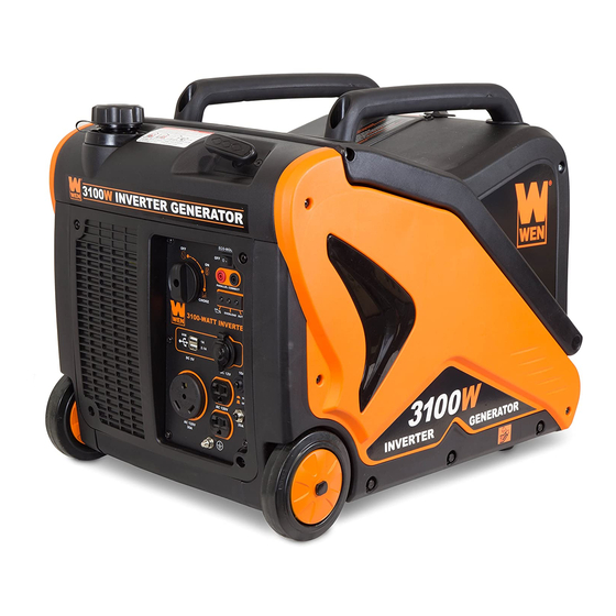
3100W INVERTER
IMPORTANT:
NEED HELP? CONTACT US!
Have product questions? Need technical support?
Please feel free to contact us at:
800-232-1195
techsupport@wenproducts.com
WENPRODUCTS.COM
GENERATOR
Model # 56310i-RV
(M-F 8AM-5PM CST)
bit.ly/WENvideo
Advertisement
Table of Contents

Related Manuals for Wen 56310i-RV


Summary of Contents for Wen 56310i-RV
- Page 1 IMPORTANT: Your new tool has been engineered and manufactured to WEN’s highest standards for dependability, ease of operation, and operator safety. When properly cared for, this product will supply you years of rugged, trouble-free performance. Pay close attention to the rules for safe operation, warnings, and cautions.
-
Page 2: Table Of Contents
TABLE OF CONTENTS Generator Identification Service Record Introduction Safety Information Generator Components Generator Preperation Starting the Generator Stopping the Generator Subsequent Starting of the Generator Using the Generator Maintenance & Care Storage & Transport Specifications Troubleshooting Exploded View and Parts List Wiring Diagram Warranty Statement... -
Page 3: Generator Identification
GENERATOR IDENTIFICATION If assistance for information or service is required, please contact the Customer Service Help Line by calling 800-232-1195; customer will be asked to provide generator information when calling. Refer to the illustration below for the location of the serial number. Record generator information in the spaces provided below. -
Page 4: Introduction
Every effort has been made to ensure the accuracy of the information in this manu- al. WEN reserves the right to change this product, manual and specifications at any time without prior notice. Please keep this manual available to all users during the entire life of the generator. - Page 5 SAFETY INFORMATION For any questions regarding the hazard and safety notices listed in this manual or on the product, please call (800) 232-1195 M-F 8-5 CST before using the generator. DANGER: CARBON MONOXIDE Using a generator indoors CAN KILL YOU IN MINUTES. Generator exhaust contains carbon monox- ide (CO).
- Page 6 150 F (65 SAVE THESE INSTRUCTIONS – This manual contains important instructions for the WEN generator that should be followed during installation and maintenance of the generator. Generators vibrate in normal use. During and after the use of the generator, inspect both the generator as well as extension and power supply cords for damage resulting from vibration.
-
Page 7: Generator Components
GENERATOR COMPONENTS Use the illustrations below to become familiar with the locations and functions of the various components and controls of this generator. Handle Lock Handle Recoil Handle Fuel Tank Control Panel Wheel Slats... -
Page 8: Generator Preperation
GENERATOR PREPARATION USING THE GENERATOR FOR THE FIRST TIME CAUTION: The following section describes the necessary steps to prepare the generator for use. If after reading this section, you are unsure about how to perform any of the steps please call (800) 232-1195 M-F 8-5 CST for customer service. - Page 9 GENERATOR PREPARATION WARNING: This generator may emit highly flammable and explosive gasoline vapors, which can cause severe burns or even death if ignited. A nearby open flame can lead to explosion even if not directly in contact with gasoline. Step 2 - ADD GASOLINE IMPORTANT: •...
-
Page 10: Starting The Generator
STARTING THE GENERATOR Before starting the generator, make sure you have read and performed the steps in the “Generator Preparation” section of this manual. If you are unsure about how to perform any of the steps in this manual please call (800) 232-1195 M-F 8-5 CST for customer service. - Page 11 STARTING THE GENERATOR STARTING THE ENGINE (FIG. 4) To start the generator, perform the following steps: 1. Unplug all electrical devices from the generator during starting. Otherwise it can be difficult to start the engine. 2. To maximize safety, make sure the generator is properly grounded (Refer to “Ground the Generator”).
-
Page 12: Stopping The Generator
STOPPING THE GENERATOR TO STOP THE GENERATOR 1. Turn off all electrical devices prior to unplugging them from the generator. Unplugging running devices can cause damage to the generator. 2. Turn the 3-in-1 knob to the “OFF” position (Fig. 4E). 3. -
Page 13: Using The Generator
The surge wattage ability of the generator covers this extra power requirement. Item Rated (Running) Wattage Surge Wattage 56310i-RV 3100 2800 Fig. 5 - Generator Wattage The total running wattage requirement of the electrical devices connected to the generator should not exceed the rated wattage of the generator itself. - Page 14 USING THE GENERATOR If the electrical specifications are not available for your electronic devices, estimate the watts requirement of the device by using the chart in Figure 6. When the rated wattage requirement of each electrical device has been determined, add these numbers to find the total rated wattage needed.
- Page 15 USING THE GENERATOR CAUTION: Do not connect 50Hz loads to the generator. SOME NOTES ABOUT POWER CORDS Long or thin cords can drain the power provided to an electrical device by the generator. When using such cords, allow for a slightly higher rated wattage requirement by the electrical device. See Figure 7 for recommended cords based on the power requirement of the electrical device.
- Page 16 MAINTENANCE HIGH ALTITUDE OPERATION ABOVE 3000 FEET The fuel system on this generator may be affected by operation at high altitudes. Proper operation can be ensured by installing an altitude kit at altitudes higher than 3000 feet above sea level. At elevations above 8000 feet, the engine may experience a decrease in performance, even with the proper altitude kit.
-
Page 17: Maintenance & Care
MAINTENANCE & CARE CHANGING/ADDING OIL Change the oil according to the Recommended Maintenance Schedule in Figure 9. Change the oil when the en- gine is warm. This will allow for complete drainage. Change oil more often if operating under heavy load or high ambient temperatures. - Page 18 MAINTENANCE & CARE SPARK PLUG MAINTENANCE (Fig. 11) The spark plug is important for proper engine operation. Spark Plug Spark Plug A good spark plug should be intact, free of deposits, and Boot properly gapped. Refer to Recommended Maintenance Schedule in Figure 8. To inspect the spark plug: 1.
-
Page 19: Storage & Transport
STORAGE & TRANSPORT PROCEDURES CAUTION: Never place any type of storage cover on the generator while it is still hot. If the generator is being stored for short periods of time (30 to 60 days), add stabilized fuel to the fuel tank until full. -
Page 20: Troubleshooting
TROUBLESHOOTING IMPORTANT: If trouble persists, please call our customer help line at (800) 232-1195 M-F 8-5 Central Time. Problem Problem Cause Cause Solution Solution Engine will not start Engine will not start Engine switch in “OFF” position Set engine switch to “CHOKE” position. Engine switch in “OFF”... -
Page 21: Exploded View And Parts List
EXPLODED VIEW AND PARTS LIST FIG. 1 CYLINDER HEAD ASSEMBLY Item Stock # Description Fig. 1-1 56310i-0101 Bolt Fig. 1-2 56310i-0102 Cover Subassembly, Cylinder Head Fig. 1-3 56310i-0103 Gasket, Cylinder Head Cover Fig. 1-4 56310i-0104 Plug, Spark Fig. 1-5 56310i-0105 Shroud, Cylinder Body Fig. - Page 22 EXPLODED VIEW AND PARTS LIST FIG. 2 CRANKCASE ASSEMBLY Item Stock # Description Fig. 2-1 56310i-0201 Crankcase Subassembly. Fig. 2-2 56310i-0202 Washer Fig. 2-3 56310i-0203 Bolt, Drain Plug Fig. 2-4 56310i-0204 Plug, End Fig. 2-5 56310i-0205 Bearing Fig. 2-6 56310i-0206 Oil-Seal Fig.
- Page 23 EXPLODED VIEW AND PARTS LIST FIG. 3 CRANKCASE COVER Item Stock # Description Fig. 3-1 56310i-0301 Cover, Crankcase Fig. 3-2 56310i-0302 Dipstick Subassembly, Oil Fig. 3-3 56310i-0303 Fig. 3-4 56310i-0304 Bearing Fig. 3-5 56310i-0305 Gasket, Crankcase Fig. 3-6 56310i-0306 Oil-Seal Fig.
- Page 24 EXPLODED VIEW AND PARTS LIST FIG. 5 CONNETING ROD Item Stock # Description Fig. 5-1 56310i-0501 Ring Assy, Piston Fig. 5-2 56310i-0502 Rod, Connecting Fig. 5-3 56310i-0503 Piston Fig. 5-4 56310i-0504 Pin, Piston Fig. 5-5 56310i-0505 Clip, Piston Pin...
- Page 25 EXPLODED VIEW AND PARTS LIST FIG. 6 VALVES, CAMSHAFT ASSEMBLY Item Stock # Description Fig. 6-1 56310i-0601 Camshaft Assy. Fig. 6-2 56310i-0602 Valve Fig. 6-3 56310i-0603 Guide, Seal Fig. 6-4 56310i-0604 Spring, Valve Fig. 6-5 56310i-0605 Seat, Valve Spring Fig. 6-6 56310i-0606 Clamp, Valve Lock Fig.
- Page 26 EXPLODED VIEW AND PARTS LIST FIG. 7 RECOIL STARTER Item Stock # Description Fig. 7-1 56310i-0701 Starter, Recoil Fig. 7-2 56310i-0702 Bolt Fig. 7-3 56310i-0703 Guide, Starting Rope Fig. 7-4 56310i-0704 Handle, Recoil Strater Cable Fig. 7-5 56310i-0705 Bolt Fig. 7-6 56310i-0706 Pulley,Starter Fig.
- Page 27 EXPLODED VIEW AND PARTS LIST FIG. 9 AIR CLEANER Item Stock # Description Fig. 9-1 56310i-0901 Gasket, Air Cleaner Fig. 9-2 56310i-0902 Fig. 9-3 56310i-0903 Air Cleaner FIG. 10 MUFFLER Item Stock # Description Fig. 10-1 56310i-1001 Bolt Fig. 10-2 56310i-1002 Shroud Fig.
- Page 28 EXPLODED VIEW AND PARTS LIST FIG. 11 FLYWHEEL AND IGNITION COIL Item Stock # Description Fig. 11-1 56310i-1101 Nut, Flywheel Fig. 11-2 56310i-1102 Impeller Fig. 11-3 56310i-1103 Screw Fig. 11-4 56310i-1104 Rotor Comp Fig. 11-5 56310i-1105 Stator Comp. Fig. 11-6 56310i-1106 Bolt Fig.
- Page 29 EXPLODED VIEW AND PARTS LIST FIG. 12 FRAME Item Stock # Description Fig. 12-1 56310i-1201 Bolt Fig. 12-2 56310i-1202 Frame Assy, Engine(Right) Fig. 12-3 56310i-1203 Frame Assy, Engine(Left) Fig. 12-4 56310i-1204 Lasso Comp. Fig. 12-5 56310i-1205 Spring Fig. 12-6 56310i-1206 Fig.
- Page 30 EXPLODED VIEW AND PARTS LIST FIG. 13 PLASTIC COVER Item Stock # Description Fig. 13-1 56310i-1301 Fig. 13-2 56310i-1302 Bolt Fig. 13-3 56310i-1303 Cross-Head Screw And Washer Comp. Fig. 13-4 56310i-1304 Shaft, Front Wheel Fig. 13-5 56310i-1305 Wheel Body,Front Fig. 13-6 56310i-1306 Right Shell Fig.
- Page 31 EXPLODED VIEW AND PARTS LIST FIG. 14 BASE AND INVERTER Item Stock # Description Fig. 14-1 56310i-1401 Plate, Bottom Fig. 14-2 56310i-1402 Seat, Frame Fig. 14-3 56310i-1403 Bolt Fig. 14-4 56310i-1404 Fig. 14-5 56310i-1405 Bolt Fig. 14-6 56310i-1406 Air Filter Inlet Comp. Fig.
- Page 32 EXPLODED VIEW AND PARTS LIST FIG. 15 SHROUD Item Stock # Description Fig. 15-1 56310i-1501 Strip, Shroud Seal Fig. 15-2 56310i-1502 Cover, Muffler Outer Fig. 15-3 56310i-1503 Cross-Head Self-Tapping Screw Fig. 15-4 56310i-1504 Muffler Insulation Gasket Fig. 15-5 56310i-1505 Cover, Muffler Side Fig.
- Page 33 EXPLODED VIEW AND PARTS LIST FIG. 16 CONTROL PANEL Item Stock # Description Fig. 16-1 56310iB-1601 Panel Assembly Fig. 16-2 56310i-1602 Idle Swtich Fig. 16-3/4 56310i-1603 Parallel Kit Fig. 16-5 56310i-1605 Indication Lights Fig. 16-6 56310i-1606 Usb Output Fig. 16-7 56310iB-1607 DC 12V Cigarette Plug Fig.
- Page 34 EXPLODED VIEW AND PARTS LIST FIG. 17 FUEL TANK Item Stock # Description Fig. 17-1 56310i-1701 Bolt Fig. 17-2 56310i-1702 Cover, Fuel Tank Fig. 17-3 56310i-1703 Fuel Filter Fig. 17-4 56310i-1704 Sleeve, Filling Oil Hole Rubber Fig. 17-5 56310i-1705 Fuel Filter Fig.
- Page 35 EXPLODED VIEW AND PARTS LIST FIG. 18 HANDLE Item Stock # Description Fig. 18-1 56310i-1801 Handle Fig. 18-2 56310i-1802 Handle Fig. 18-3 56310i-1803 Blot Fig. 18-4 56310i-1804 Screw Fig. 18-5 56310i-1805 Rotor Arm Fig. 18-6 56310i-1806 Rotor Arm Fig. 18-7 56310i-1807 Nylon Nut Fig.
-
Page 36: Wiring Diagram
WIRING DIAGRAM... -
Page 37: Warranty Statement
WEN® will repair or replace, at its discretion, any part that is proven to be defective in materials or workman- ship under normal use during the two (2) years warranty period. Warranty repairs or replacements will be made without charge for parts or labor. - Page 38 Thanks for remembering...
Need help?
Do you have a question about the 56310i-RV and is the answer not in the manual?
Questions and answers