Table of Contents
Advertisement
Your new tool has been engineered and manufactured to WEN's highest standards for dependability,
ease of operation, and operator safety. When properly cared for, this product will supply you years
of rugged, trouble-free performance. Pay close attention to the rules for safe operation, warnings,
and cautions. If you use your tool properly and for intended purpose, you will enjoy years of safe,
reliable service.
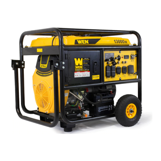
13KW PORTABLE
IMPORTANT:
NEED HELP? CONTACT US!
Have product questions? Need technical support?
Please feel free to contact us at:
800-232-1195
techsupport@wenproducts.com
WENPRODUCTS.COM
GENERATOR
(M-F 8AM-5PM CST)
Model # 5613K
bit.ly/WENvideo
Advertisement
Table of Contents

Subscribe to Our Youtube Channel
Related Manuals for Wen 5613K


Summary of Contents for Wen 5613K
- Page 1 IMPORTANT: Your new tool has been engineered and manufactured to WEN’s highest standards for dependability, ease of operation, and operator safety. When properly cared for, this product will supply you years of rugged, trouble-free performance. Pay close attention to the rules for safe operation, warnings, and cautions.
-
Page 2: Table Of Contents
TABLE OF CONTENTS Generator Identification Service Record Introduction Safety Information General Safety Procedures Important Safety Instructions Generator Components Generator Preperation Starting the Generator Stopping the Generator Subsequent Startings of the Generator Using the Generator Maintenance & Care Storage & Transport Specifications Troubleshooting Exploded View and Parts List... -
Page 3: Generator Identification
Refer to the illustration below for the location of the serial number. Record generator information in the spaces provided below. DATE OF PURCHASE: ______________________________________________ PURCHASED FROM: ______________________________________________ GENERATOR MODEL NUMBER: 5613K ENGINE SERIAL NUMBER: _________________________________________ Serial Number SERVICE RECORD Record Service Dates:... -
Page 4: Introduction
Every effort has been made to ensure the accuracy of the information in this manual. WEN® reserves the right to change this product and specifications at any time without prior notice. Please keep this manual available to all users during the entire life of the generator. -
Page 5: General Safety Procedures
GENERAL SAFETY PROCEDURES For any questions regarding the hazard and safety notices listed in this manual or on the product, please call (800) 232-1195 M-F 8-5 CST before using the generator. DANGER: CARBON MONOXIDE Using a generator indoors CAN KILL YOU IN MINUTES. Generator exhaust contains carbon monoxide (CO). This is a poison gas you cannot see or smell. -
Page 6: Important Safety Instructions
Turn off all connected electrical devices before stopping the generator. Turn the engine switch to “OFF” position when the engine is not running. IMPORTANT SAFETY INSTRUCTIONS SAVE THESE INSTRUCTIONS – This manual contains important instructions for the WEN generator that ®... -
Page 7: Generator Components
GENERATOR COMPONENTS Use the illustrations below to become familiar with the locations and functions of the various components and controls of this generator. Handle 12 VDC Receptacle Fuel Gauge Circuit Breaker Fuel Tank Cap Hour / Voltage Meter Choke Lever Frame Hook Battery... -
Page 8: Attach Feet
ASSEMBLY In order to best protect the generator while in the package, this product comes with some components disassem- bled. Please complete the following assembly steps before proceeding to use the generator. For ease of assembly, we recommend attaching the components in the order listed in this manual. If after reading this section, you are unsure about how to perform any of the steps, please call (800) 232-1195 M-F 8-5 CST for customer service. -
Page 9: Attach Handles
ASSEMBLY ATTACH HANDLES The handles attach to the generator frame on the same side as the recoil starter (left side when facing control panel). To attach the handles to the generator frame, perform the following steps: 1. Take one handle bracket and line up the holes in the handle bracket with the holes on the generator frame. 2. -
Page 10: Generator Preperation
GENERATOR PREPARATION USING THE GENERATOR FOR THE FIRST TIME The following section describes steps necessary to prepare the generator for use. If after reading this sec- tion, you are unsure about how to perform any of the steps please call (800) 232-1195 M-F 8-5 CST for customer service. - Page 11 GENERATOR PREPARATION Step 2 - ADD GASOLINE WARNING: This generator may emit highly flammable and explosive gasoline vapors, which can cause severe burns or even death if ignited. A nearby open flame can lead to explosion even if not directly in contact with gasoline. Use fresh (within 30 days from purchase), lead-free gasoline with a minimum of 87 octane rating.
- Page 12 GENERATOR PREPARATION STEP 4 – CONNECT THE BATTERY Battery: 12VDC 18AH WARNING: Battery gives off explosive hydrogen gas. • Keep battery away from spark, flame, or cigarette. • Do not connect or disconnect battery while generator is running. • Service or use battery only in well ventilated areas. WARNING: Battery contains sulfuric acid.
-
Page 13: Starting The Generator
STARTING THE GENERATOR Before starting the generator, make sure you have read and performed the steps in the “Generator Prepera- tion” section of this manual. If you are unsure about how to perform any of the steps in this manual please call (800)232-1195 M-F 8-5 CST for customer service. - Page 14 STARTING THE GENERATOR STARTING THE ENGINE To start the generator, perform the following steps: 1. Make sure no electrical devices are connected to the generator. Such devices can make it difficult for the en- gine to start. 2. Check that the generator is properly grounded (see Figure 3, “Ground the Generator”). 3.
-
Page 15: Stopping The Generator
STOPPING THE GENERATOR TO STOP THE GENERATOR 1. Turn off all electrical devices prior to unplugging them from the generator. Unplugging running devices can cause damage to the generator. 2. Turn the “ON/OFF” switch to the “OFF” position. 3. Turn the fuel valve to the “OFF” (horizontal) position. WARNING: Allow the generator to cool for several minutes before touching areas that become hot dur- ing use. - Page 16 SUBSEQUENT STARTING OF THE GENERATOR WARNING: This generator may emit highly flammable and explosive gasoline vapors, which can cause severe burns or even death if ignited. A nearby open flame can lead to an explosion even if it is not directly in contact with fuel.
-
Page 17: Using The Generator
The surge wattage ability of the generator covers this extra power requirement. Item Rated (Running) Wattage Surge Wattage 5613K 11000 13000 Figure 6 - Generator Wattage The total running wattage requirement of the electrical devices connected to the generator should not exceed the rated wattage of the generator itself. - Page 18 USING THE GENERATOR CAUTION: The generator can run at its surge wattage capacity for only a short time. Connect electrical devices requiring a rated (running) wattage equal to or less than the rated wattage of the generator. Never connect devices requiring a rated wattage equal to the surge wattage of the generator.
- Page 19 USING THE GENERATOR SOME NOTES ABOUT POWER CORDS Long or thin cords can drain the power provided to an electrical device by the generator. When using such cords, allow for a slightly higher rated wattage requirement by the electrical device. See Figure 8 for recommended cords based on the power requirement of the electrical device.
-
Page 20: Maintenance & Care
MAINTENANCE & CARE Proper routine maintenance of the generator will help prolong the life of the machine. Please perform mainte- nance checks and operations according to the schedule in Figure 9. If there are any questions about the maintenance procedures listed in this manual, please call (800) 232-1195 M-F 8-5CST. -
Page 21: Air Cleaner Maintenance
MAINTENANCE & CARE CHANGING/ADDING OIL Change the oil according to the Recommended Maintenance Schedule in Figure 9. Change the oil when the en- gine is warm. This will allow for complete drainage. Change oil more often if operating under heavy load or high ambient temperatures. -
Page 22: Fuel Filter Cup Cleaning
MAINTENANCE & CARE FUEL FILTER CUP CLEANING The fuel filter cup is a small well underneath the fuel valve. It helps to trap dirt and water that may be in the fuel tank before it can enter the engine. To clean the fuel filter cup: 1. -
Page 23: Storage & Transport
MAINTENANCE & CARE DRAINING THE FUEL TANK Clean fuel tank each year or before storing the generator for extended periods of time. To drain the fuel tank and carburetor: 1. Turn the fuel valve to the “OFF” position. 2. Remove the fuel line between the fuel valve and carburetor. CAUTION: A small amount of fuel may leak from the hose during removal. -
Page 24: Specifications
SPECIFICATIONS DC output Rated Voltage 12 V DC Rated Amperage 8.3 A Rated Wattage 100 W AC output Rated Wattage 11000 Watts Surge Wattage 13000 Watts Rated Voltage 120 V/ 240 V Rated Amperage 91.6 A/ 45.8 A Frequency 60 Hz Phase Single Length: 32.50 inches... -
Page 25: Troubleshooting
TROUBLESHOOTING IMPORTANT: If trouble persists, please call our customer help line at (800) 232-1195 M-F 8-5 Central Time. Problem Cause Solution Engine switch is set to Engine will not start "OFF". Set engine switch to "ON". Fuel valve is turned to "OFF". -
Page 26: Exploded View And Parts List
EXPLODED VIEW AND PARTS LIST FIG.1 CYLINDER HEAD ASSEMBLY / SPARK PLUG ITEM STOCK # DESCRIPTION 5613K-0101 BOLT WASHER, CYLINDER HEAD COVER 5613K-0102 COVER, CYLINDER HEAD 5613K-0103 GASKET, CYLINDER HEAD COVER 5613K-0104 SPARK PLUG 5613K-0105 BOLT, CYLINDER HEAD 5613K-0106 LEFT CYLINDER HEAD... - Page 27 5613K-0309 BOLT 3-10 5613K-0310 BOLT 3-11 5613K-0311 PIN 3-12 5613K-0312 OIL PUMP 3-13 5613K-0313 COVER, OIL PUMP 3-14 5613K-0314 SPRING, PRESSURE RELIEF VALVE 3-15 5613K-0315 STEEL BALL 3-16 5613K-0316 OIL STRAINER 3-17 5613K-0317 GEAR ASSY, GOVERNOR 3-18 5613K-0318 DIPSTICK 3-19 5613K-0319 GASKET, OIL PUMP FIG.4 CRANKSHAFT / CONNETING ROD...
- Page 28 ITEM STOCK # DESCRIPTION 5613K-0601 SHROUD SHIELD 5613K-0602 SCREW 5613K-0603 NUT 5613K-0604 SHROUD ASSY. 5613K-0605 DECORATION PLATE, FAN SHIELD 5613K-0606 LOCK HANDLE FIG.7 CYLINDER BODY SHROUD/ LOWER SHIELD ITEM STOCK # DESCRIPTION 5613K-0701 SHROUD 2, CYLINDER BODY 5613K-0702 SHUTOFF WIRE, IGNITION COIL...
- Page 29 10-8 5613K-1008 FLYWHEEL ASSEMBLY 10-9 5613K-1009 WASHER 10-10 5613K-1010 FLYWHEEL BOLT 10-11 5613K-1011 IMPELLER 10-12 5613K-1012 IMPELLER SETTING TRAY 10-13 5613K-1013 BOLT 10-14 5613K-1014 PIN 10-15 5613K-1015 STARTING MOTOR ASSEMBLY 10-16 5613K-1016 BOLT 10-17 5613K-1017 OIL PROTECTOR 10-18 5613K-1018 BOLT FIG.11 THROTTLE CONTROL ASSEMBLY...
- Page 30 13-9 5613K-1309 FUEL COCK 13-10 5613K-1310 FUEL HOSE 13-11 5613K-1311 CLAMP 13-12 5613K-1312 ONE-WAY VALVE 13-13 5613K-1313 CUSHION, FUEL TANK 13-15 5613K-1315 LOCK CHAIN, FUEL TANK CAP 13-16 5613K-1316 CLIP, LOCK CHAIN FIG.14 FRAME ITEM STOCK # DESCRIPTION 14-1 5613K-1401 FRAME...
- Page 31 15-15 5613K-1515 OVERCURRENT PROTECTION 15-16 5613K-1516 TIMER 15-17 5613K-1517 DOUBLE-POLE BREAKER 15-18 5613K-1518 GROUND TERMINAL 15-19 5613K-1519 SOCKET ASSY 15-20 5613K-1520 WATER PROOF COVER 15-21 5613K-1521 SOCKET ASSY 15-22 5613K-1522 WATER PROOF COVER 15-23 5613K-1523 SOCKET ASSY 15-24 5613K-1524 SOCKET ASSY...
- Page 32 5613K-1705 CONNECTOR, HANLDE 17-6 5613K-1706 17-7 5613K-1707 BRACKET, FRAME CUSHION 17-8 5613K-1708 FRAME CUSHION 17-9 5613K-1709 WHEEL 17-10 5613K-1710 WHEEL AXLE 17-11 5613K-1711 WASHER 17-12 5613K-1712 LOCK NUT 17-13 5613K-1713 WASHER 17-14 5613K-1714 BOLT 17-15 5613K-1715 PIN SHAFT 17-16 5613K-1716 CABLE FIG.18 HOOK PART...
-
Page 33: Wiring Diagram
WIRING DIAGRAM... -
Page 34: Warranty Statement
WEN® will repair or replace, at its discretion, any part that is proven to be defective in materials or workman- ship under normal use during the two (2) years warranty period. Warranty repairs or replacements will be made without charge for parts or labor. - Page 35 Thanks for remembering...
Need help?
Do you have a question about the 5613K and is the answer not in the manual?
Questions and answers