
Related Manuals for Acteon XMIND TRIUM


Summary of Contents for Acteon XMIND TRIUM
- Page 1 Operator’s Manual for U.S. and Canadian Markets CMJN : 15/0/0/85 Pantone 432C RAL 7024 (Graphite gr CMJN : 80/0/10/0 Pantone 306C RAL 220 80 25 Operator’s manual • X-Mind trium • V0G • (13) • 10/2017 • NTR0EN040G...
-
Page 2: Table Of Contents
E N G L I S H CONTENTS INTRODUCTION ..........................4 1.1 CAUTIONS ................................4 1.2 IDENTIFICATION TAGS ............................5 1.3 POSITION OF THE IDENTIFICATION LABELS ......................8 DESCRIPTION ..........................9 2.1 OPERATOR’S WORKSTATION ..........................9 2.2 X-MIND TRIUM REMOTE CONTROL........................9 2.3 X-MIND TRIUM MEDICAL DEVICE ........................10 2.4 X-MIND TRIUM CONFIGURATIONS ........................12 2.5 EXAMS ..................................12 2.6 CONTROL PANELS ...............................14... - Page 3 E N G L I S H ANNEXES ...........................54 11.1 DEVICE POWER SUPPLY .............................54 11.2 ELECTRICAL CLASSIFICATION (IEC 60601-1) ....................54 11.3 X-RAY ASSEMBLY AND X-RAY TUBE ........................54 11.4 DEGREE OF PROTECTION PROVIDED BY ENCLOSURES ................56 11.5 DEVICE MECHANICAL DATA ..........................56 11.6 WORKSTATION FEATURES ..........................57 11.7 DETECTORS .................................57 11.8 SCANNING PARAMETERS –...
-
Page 4: Introduction
E N G L I S H INTRODUCTION Thank you for choosing the X-MIND trium. The electro medical equipment described in this manual refers to the X-Mind trium medical device. X-MIND trium is a radiological device and must be used and handled only by specialised surgeons, dentists and authorised and duly trained personnel, who meet the requirements provided by the national laws in force in the country of installation. -
Page 5: Identification Tags
Hounsfield Unit. Standard reference scale used to describe radiodensity in systems. Acteon imaging Suite software that manages all the functional aspects of the X-MIND trium system, including: patient database, patient acquisition, calibrations, quality tests, maintenance, display that allows the operator to make the diagnosis and treatment planning. - Page 6 E N G L I S H X-RAY BEAM LIMITER label CAUTION X-RAYS LABEL CAUTION LASER BEAM LABEL PAN DETECTOR LABEL Operator’s manual • X-Mind trium • V0G • (13) • 10/2017 • NTR0EN040G...
- Page 7 E N G L I S H REMOVABLE DETECTOR LABEL 3D DETECTOR LABEL CEPH ARM LABEL ETL MARKING UDI LABEL Operator’s manual • X-Mind trium • V0G • (13) • 10/2017 • NTR0EN040G...
-
Page 8: Position Of The Identification Labels
E N G L I S H 1.3 POSITION OF THE IDENTIFICATION LABELS Operator’s manual • X-Mind trium • V0G • (13) • 10/2017 • NTR0EN040G... -
Page 9: Description
• Periodic quality Tests The workstation must have installed the following modules: • ACTEON IMAGING SUITE (AIS) equipment management software + 2D diagnostic analysis • AIS 3D app (CBCT) Communication with the medical device occurs by means of Ethernet protocol. -
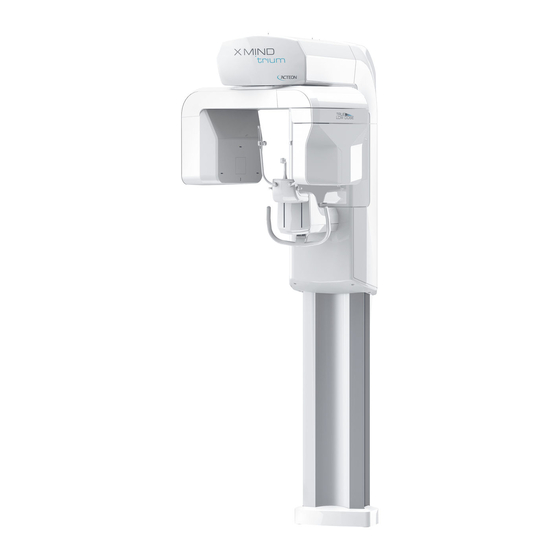
Page 10: X-Mind Trium Medical Device
E N G L I S H X-MIND trium Light The X-MIND trium Light is an indicator light that warns that X-ray emission is in progress. It indicates no entry into the room when the red light is on; it also has a triangular danger sign that warns of X-ray hazards. 2.3 X-MIND TRIUM MEDICAL DEVICE The X-MIND trium medical device for PAN/CBCT models consists of the following parts: Control panel. - Page 11 E N G L I S H PAN detector. This flat panel detector is indicated for use in generating radiographic images of the maxillo-facial region, more specifically it is dedicated for PAN acquisitions. Patient support. The patient support allows stabilising and immobilising the patient. It can be moved vertically in order to obtain the best superimposition between the patient’s head anatomy and the height of Field of View (FOV).
-
Page 12: X-Mind Trium Configurations
E N G L I S H 2.4 X-MIND TRIUM CONFIGURATIONS X-MIND trium can be sold in these configurations: PAN only • The equipment can carry out uniquely exams of the PAN group (PAN, TMJ, Sinus); • The image detector is fixed to the PAN bay; •... - Page 13 E N G L I S H 2) Sectorial panoramic with improved orthogonality · Full scan · Right side only · Left side only 3) Frontal panoramic 4) Bitewings 5) Frontal temporomandibular joint with closed or open mouth · Both sides ·...
-
Page 14: Control Panels
E N G L I S H - medium - large · WOMAN - small - medium - large · CHILD - small - medium - large For the panoramic group and the cephalometric group, the operator can still modify the loading factors by means of dedicated sliders. -
Page 15: Keys Description
E N G L I S H CAUTION : Some of the keys give the operator the possibility to move parts of the equipment. When pressing them the operator must check carefully the patient and, in case of possible collision between equipment and patient, stop immediately the movement by releasing the key. -
Page 16: Light Indicators
E N G L I S H Horizontal movements keys These keys move the U arm in the arrows direction, in order to place the LASER in the required position on patient face. By single pressure of one of these keys the rotating U-arm is moved by 1 mm in the arrow direction. These keys are enabled only for a sub-set of exams;... -
Page 17: Emergency Switches
E N G L I S H 2. X-ray emission LED. Remains on during the entire acquisition. 3. Remote emergency switch. Allows stopping the device in the event of emergency. 4. X-ray emission switch. Activates acquisition. 2.10 EMERGENCY SWITCHES This device is equipped with two emergency switches that allow to stop the movement of parts and X-ray emission in the event of an emergency. -
Page 18: X-Ray Exposure Switch
E N G L I S H 2.11 X-RAY EXPOSURE SWITCH To activate the exposure, the operator must press and hold the X-ray exposure switch for the entire acquisition. Meanwhile, the yellow X-ray exposure LED stays ON to indicate X-ray emission. If the operator removes his/her finger from the exposure button before acquisition is complete, X-ray emission and U-Arm rotation will be interrupted and the X-ray exposure LED will turn off. -
Page 19: Accessories
E N G L I S H 1. Ear rest 2. Ear rest knob 3. Nose support To adapt to the patient’s anatomy, the CEPH head support is equipped with: • Ear rest knob for horizontal ear rest movement. • Nose support, that can be manually moved in horizontal and in vertical. 2.14 ACCESSORIES Temple rest The temple rest supports provide support, frontal and lateral stability to the patient’s head for all types of examination. - Page 20 E N G L I S H TMJ nose support This support must be used for TMJ examinations since it is specifically designed to stabilize the patient’s head in both open mouth and closed mouth conditions. Calibration tray and geometric calibration phantom The Calibration tray is used to position the geometric calibration phantom during the calibration procedure of the CBCT apparatus.
-
Page 21: Switching On / Off The System
E N G L I S H SWITCHING ON / OFF THE SYSTEM 3.1 SWITCHING ON To turn the system ON, proceed as follows: • Ensure that the system is properly connected to the power supply. • Switch the medical device by setting the Main switch to ON position (I). The main switch is located below the patient support. 1 Main switch •... -
Page 22: Switching Off
E N G L I S H Not connected • This icon is shown during device start-up, when workstation is turned off or if there is a connection problem. Connected • The medical device is ready to perform acquisitions, calibrations and quality tests. 3.2 SWITCHING OFF •... -
Page 23: Pre Acquisition
• Ensure that the medical device is properly calibrated. 4.2 CREATING OR SELECTING PATIENT DATA Patient data must be created or selected from patient database. To do so, follow the procedure described in the manual of Acteon imaging suite software. - Select the exam 4.3 INSTRUCTING THE PATIENT •... -
Page 24: Positioning The Patient For Pan/Cbct Exams
E N G L I S H 4.4 POSITIONING THE PATIENT FOR PAN/CBCT EXAMS This section describes the procedure to place the patient on the device and to carry out all panoramic and CBCT scan. • Install the patient support best suited to the examination to be carried out, as described in the table here below: Support Examination Specific note... - Page 25 E N G L I S H • Ask the patient to approach the head support and hold of the handlebar. Ask the patient to have a natural posture and relax. • Ask the patient to firmly grasp the handgrip with both hands. •...
-
Page 26: Pan Acquisition
E N G L I S H PAN ACQUISITION 5.1 SELECTING THE EXAM TYPE · From the AIS tool bar press the PAN button to enter in the acquisition window. · From the acquisition window (refer to AIS Operator’s manual for the description of the acquisition window) select the patient’s type (man, woman, child) and size (small, medium, large). - Page 27 E N G L I S H • The picture below shows the proper placement of the feet or the wheelchair respect to the base for devices installed with the accessory “Self-standing base”. In any case, the patient may also stand in natural and more comfortable position if he/she cannot hold the above described position (e.g.
-
Page 28: Execution Of The Pan Exam
E N G L I S H • If it is necessary, adjust the machine in order to centre the canine laser plane on the patient canine for PAN and SINUS exams and on temporo-mandibular jont for TMJ exams. Move the U-arm by pressing the dedicated keys to adjust the anterior or posterior directions. - Page 29 E N G L I S H A = X-ray emission switch B = X-ray emission LED • Keep the switch pressed for the whole duration of the exam until the U-arm stops. If the switch is released earlier, the X-ray emission and the carriage movements will be stopped and the exam is irremediably interrupted (“dead man”...
-
Page 30: Cbct Acquisition
E N G L I S H CBCT ACQUISITION 6.1 SELECTING THE EXAM TYPE · From the AIS tool bar press the CBCT button to enter in the acquisition window. · From the acquisition window (refer to AIS Operator’s manual for the description of the acquisition window) select the patient type (man, woman, child) and size (small, medium, large). - Page 31 E N G L I S H Interested area Clinic indications Technical data (mm X mm) 60 x 60 Half dental arch This examination is suitable for Nominal FOV: cylindrical, 60 mm x 60 mm investigating localised dental (diameter x height) problems and planning single Resolution: low,...
-
Page 32: Patient Positioning
E N G L I S H RESOLUTION selection Set high resolution (High Quality) to improve the diagnostic accuracy of endodontic-specific tasks such as the visualization of small features including calcified/accessory canals, missed canals, disruptions in the periodontal ligament space, small alterations, etc. - Page 33 E N G L I S H The intersection between the mid-sagittal plane laser and the coronal plane laser represents the Axis of Rotation (AOR) of the scanning apparatus, that is the central axis of the acquired volume. Once the patient is positioned correctly with respect to the lasers, adjust the chin rest support by means of the control panel commands in order to reach the correct position.
-
Page 34: Execution Of The Cbct Exam
E N G L I S H Close temple rest on the patient forehead and gently move the patient’s head to the correct position with his/her mid-sagittal plane corresponding to the mid-sagittal LASER. 6.3 EXECUTION OF THE CBCT EXAM • Once the patient is correctly positioned, press “O position” key. •... - Page 35 E N G L I S H A = X-ray emission switch B = X-ray emission LED • In case of CBCT scan, keep the switch pressed for the whole duration of the exam until the U-arm stops. If the switch is released earlier, the X-ray emission and the carriage movements will be stopped and the exam is irremediably interrupted (“dead man”...
-
Page 36: Ceph Acquisition
E N G L I S H CEPH ACQUISITION 7.1 SELECTING THE EXAM TYPE · From the AIS tool bar press the CEPH button to enter in the acquisition window. · From the acquisition window (refer to AIS Operator’s manual for the description of the acquisition window) select the patient type (man, woman, child) and size (small, medium, large). - Page 37 E N G L I S H • Turn nose support in vertical position and move it vertically and horizontally until the extreme side of the support is on the nose root; For CARPUS exam only, follow the next instructions: + Place the dedicated carpus support (a) on the CEPH patient support, lifting it with the aid of the two pins (p), then fixing it with the screw (s1).
-
Page 38: Execution Of The Ceph Exam
E N G L I S H 7.3 EXECUTION OF THE CEPH EXAM • Once the patient is correctly positioned, press “O position button” exam button. • The green status indicator will be ON and the U-arm will reach the start position. •... -
Page 39: Releasing The Patient
E N G L I S H RELEASING THE PATIENT • Go inside the radiologic room, open temple rest or the ear rests and ask patient to move carefully from the equipment. • Image will be available on the PC connected to Trium. •... -
Page 40: Maintenance, Cleaning And Disposal
Repairs and replacements of any component must be carried out solely by authorized and highly qualified personnel and only using genuine spare parts supplied by de Götzen® S.r.l. - ACTEON Group. 9.2 CLEANING Clean the external surface using a damp cloth with non-corrosive and non oil-based detergent; disinfect the external surface using a non-aggressive medical detergent. -
Page 41: Troubleshooting
E N G L I S H TROUBLESHOOTING 10.1 ERROR CODES AND REQUIRED ACTIONS The following table describes the meaning of the various error codes: CODE DESCRIPTION MEANING Serious error Serious error and reduced functionality. The detected fault is too serious for automatic restoration. The results of the operation are not valid. -
Page 42: Trium Errors
E N G L I S H 10.2 TRIUM ERRORS CODE Message / Description Solution "CHECK INTERNAL ETHERNET "Reset error from workstation; if error remains restart trium Hw errror: mainboard and ETH switch and workstation. do not communicate If error remains technical service is required: + check connection cable between mainboard and ETHERNET In this condition trium and switch... - Page 43 E N G L I S H "Reset error from workstation; if error remains restart trium and workstation. If error remains technical service is required: check all ethernet connections between trium image detectors "PCDRV_COMM_WDOG_ERR and workstation; PC communication timeout" check trium ethernet switch; check that workstation configuration is in accordance with requirements (network interface card, installed anti-virus, firewall disabled…)"...
- Page 44 E N G L I S H "Reset error from workstation; if error remains restart trium and workstation. "S_AXIS_ERR_RES_TOUT If error remains technical service is required: S-axis reset timeout (image detectors check motor and its cable; slider on Uarm)" check optoswitch and its cable; check/replace main board."...
- Page 45 E N G L I S H "B_AXIS_ERR_RUN_PTPT Reset error from workstation; if error remains restart trium and Unexpected FSM condition during workstation. B-axis position adjustment" "R_AXIS_ERR_RUN_LIMI Reset error from workstation; if error remains restart trium and R-axis position out of range" workstation.
- Page 46 E N G L I S H "Reset error from workstation; if error remains restart trium "HI_VOLT_ENA_IN_IDLE and workstation. Inverter board error: If error remains technical service is required: GENERAL STATE ERROR, bit 5 - HV check cables between Inverter board and tubehead; ENABLE SIGNAL ACTIVE IN IDLE check/replace tubehead;...
- Page 47 E N G L I S H "Reset error from workstation; if error remains restart trium "VOLT_UPP_LIM_ON_NEG and workstation. Inverter board error: If error remains technical service is required: GENERAL STATE ERROR, bit 15 - check cables between Inverter board and tubehead; VOLTAGE TOO HIGH ON NEGATIVE check/replace tubehead;...
- Page 48 E N G L I S H "Reset error from workstation; if error remains restart trium and workstation. "EXP_TIME_IS_LOW_LIM Inverter board error: If error remains technical service is required: GENERAL STATE ERROR, bit 28 - check cables between Inverter board and tubehead; EXPOSURE TIME TOO SHORT"...
- Page 49 E N G L I S H "Reset error from workstation; if error remains restart trium "IS_OVER_LOAD_ON_POS and workstation. Inverter board error: If error remains technical service is required: GENERAL STATE ERROR, bit 37 - check cables between Inverter board and tubehead; OVERLOAD ON POSITIVE HV STAGE"...
- Page 50 E N G L I S H "EMERGENCY_STOP_DONE Trium has rebooted after releasing Reset error from workstation. the emergency stop button" "Reset error from workstation; if error remains restart trium "COL_DCFI_LW_VOLTAGE and workstation. Hanning board error code 1 - Under- If error remains technical service is required: voltage"...
- Page 51 E N G L I S H "Reset error from workstation; if error remains restart trium "COL_DCFI_SFTW_RESET and workstation. Hanning board error code 133 - Reset If error remains technical service is required: by SW" check/replace column (Hanning) board." "Reset error from workstation; if error remains restart trium "COL_DCFI_E2PROM_CRC and workstation.
- Page 52 E N G L I S H "Reset error from workstation; if error remains restart trium and workstation. "AUX_CBCT_LINK_ERROR If error remains technical service is required: CAN communication error between check CAN cables between Maiboard and AUX CBCT; Mainboard and AUX CBCT board" check/replace Mainboard;...
- Page 53 E N G L I S H "Reset error from workstation; if error remains restart trium and workstation. "HORZ_ONE_RESET_TOUT If error remains technical service is required: Timeout of primary collimator check motor and its cable; horizontal axis reset" check optoswitch and its cable; check/replace AUX CBCT board."...
-
Page 54: Annexes
E N G L I S H ANNEXES 11.1 DEVICE POWER SUPPLY Type of power supply Single-phase alternating current power supply Supply voltage 100 – 240 V Maximum voltage variation ±10% Frequency 50 – 60 Hz Absorbed current (@ 90 kV, 10 mA) 7 A (@ 240 V) 15 A (@ 100 V) Standby current... - Page 55 E N G L I S H CBCT Reference axis position CEPH 3.4 mm Al for PAN/CEPH at 85 kV 5.2 mm Al for CBCT at 90 kV Total filtration 2.8 mm Al for PAN/CEPH at 85 kV 7.0 mm Al for CBCT at 90 kV Inherent filtration 0.5 mm Al Leakage radiation...
-
Page 56: Degree Of Protection Provided By Enclosures
E N G L I S H Current-time product accuracy ± (10% + 0.2 mAs) Dose reproducibility <0.05 Maximum anodic current 12 mA (typical 8 mA) Loading factors related to the maximum specified energy Continuous mode: 85 kVp @ 10 mA input in one hour Nominal X-ray Tube Voltage together with the highest X-ray Tube Current obtainable from the High-Voltage Generator... -
Page 57: Workstation Features
E N G L I S H Weight PAN: 170 kg PAN/CBCT: 185 kg PAN/CBCT With CEPH: 215 kg Mechanical configuration Wall mount Left column/Right column Patient position: Standing, seated or on wheel-chair 11.6 WORKSTATION FEATURES Intel Xeon 2 GHz Hard Disk 1 TB Graphic Processor (minimum) -
Page 58: Scanning Parameters - Pan/Ceph
E N G L I S H Manufacturer Hamamatsu Photonics K.K. Model FPD C12280D-40 Image voxel size 75 µm (minimum slice thickness) Active area 121.6 x 123.1 mm 40 mm x 60 mm 60 mm x 60 mm 80 mm x 80 mm FOV (diameter x height) 110 mm x 80 mm NOTE :... -
Page 59: Client Pc Minimum Requirements
E N G L I S H 11.11 CLIENT PC MINIMUM REQUIREMENTS IT’S MANDATORY TO RESPECT CLIENT PC MINIMUM REQUIREMENTS T H E C H O I C E O F P C F O R A I S C L I E N T, I S U N D E R C U S T O M E R R E S P O N S I B I L I T Y. A W R O N G C H O I C E , W I T H O U T R E S P E C T I N G M I N I M U M R E Q U I R E M E N T, W I L L N OT B E U N D E R A C T E O N G R O U P R E S P O N S I B I L I T Y. -
Page 60: Intended Environment
E N G L I S H 11.12 INTENDED ENVIRONMENT Clinical environment conditions (use conditions): • Temperature: 10 to 30°C • Relative humidity: 25 to 75 % • Atmospheric pressure: 850 to 1060 hPa Transportation environment conditions: • Temperature: 0 to 50°C •... - Page 61 E N G L I S H WITH SELF STANDING Operator’s manual • X-Mind trium • V0G • (13) • 10/2017 • NTR0EN040G...
-
Page 62: List Of International Standards And Directives
E N G L I S H 11.14 LIST OF INTERNATIONAL STANDARDS AND DIRECTIVES MDD 93/42 EEC and subsequent amendments In compliance with the classification indicated in the Medical Device Directive 93/42/EEC, Annex IX, article 10: “Active devices intended to emit ionising radiation and intended for diagnostic radiology”, the system is classified as: Class IIb IEC/EN 60601-1:1988, 2nd edition IEC 60601-1/A1... - Page 63 E N G L I S H DAP values for PANORAMIC exams Exposure 13,5 7,28 4,98 4,24 12,38 7,16 10,74 7,16 10,74 14,34 6,94 Time [kV] [mA] [mGycm2] Operator’s manual • X-Mind trium • V0G • (13) • 10/2017 • NTR0EN040G...
- Page 64 E N G L I S H Exposure 13,5 7,28 4,98 4,24 12,38 7,16 10,74 7,16 10,74 14,34 6,94 Time [kV] [mA] [mGycm2] Operator’s manual • X-Mind trium • V0G • (13) • 10/2017 • NTR0EN040G...
- Page 65 E N G L I S H Exposure 13,5 7,28 4,98 4,24 12,38 7,16 10,74 7,16 10,74 14,34 6,94 Time [kV] [mA] [mGycm2] Operator’s manual • X-Mind trium • V0G • (13) • 10/2017 • NTR0EN040G...
- Page 66 E N G L I S H DAP values for CBCT exams Dental FOV 40x40 Standard Medium High Tube voltage Tube current Patient gender Patient size [kV] [mA] [mGycm^2] [mGycm^2] [mGycm^2] SMALL 140,4 168,5 210,6 CHILD MEDIUM 187,2 224,6 280,8 LARGE 234,0 280,8...
- Page 67 E N G L I S H SMALL 564,2 677,0 846,3 MEDIUM 752,2 902,7 1128,4 LARGE 940,3 1128,4 1410,4 Operator’s manual • X-Mind trium • V0G • (13) • 10/2017 • NTR0EN040G...
- Page 68 E N G L I S H DAP values for CEPH group exams CEPH LL CEPH AP/PA Tube voltage Tube current CEPH LL CEPH AP/PA CARPUS Child Child [kV] [mA] [mGycm^2] 12,1 12,4 10,2 15,1 12,1 10,0 14,9 12,3 18,1 14,5 12,0 17,4...
- Page 69 E N G L I S H CEPH LL CEPH AP/PA Tube voltage Tube current CEPH LL CEPH AP/PA CARPUS Child Child [kV] [mA] [mGycm^2] 15,1 12,3 19,2 15,0 12,3 18,1 14,8 23,0 18,0 14,7 21,1 17,2 26,8 21,0 17,2 24,1 19,7 30,7...
- Page 70 E N G L I S H CEPH LL CEPH AP/PA Tube voltage Tube current CEPH LL CEPH AP/PA CARPUS Child Child [kV] [mA] [mGycm^2] 21,3 17,3 27,9 21,4 17,5 24,8 20,1 32,6 25,0 20,4 28,4 23,0 37,2 28,6 23,3 31,9 25,9 41,9...
- Page 71 E N G L I S H CEPH LL CEPH AP/PA Tube voltage Tube current CEPH LL CEPH AP/PA CARPUS Child Child [kV] [mA] [mGycm^2] 28,5 23,0 38,3 29,1 23,6 32,6 26,3 43,7 33,2 27,0 36,7 29,6 49,2 37,4 30,4 40,8 32,9 54,7...
- Page 72 E N G L I S H CEPH LL CEPH AP/PA Tube voltage Tube current CEPH LL CEPH AP/PA CARPUS Child Child [kV] [mA] [mGycm^2] 36,8 29,6 50,3 37,8 30,7 41,5 33,3 56,5 42,6 34,5 46,1 37,0 62,8 47,3 38,4 18,8 15,1 25,7...
- Page 73 E N G L I S H 11.15.2 DOSIMETRIC INDICATIONS IN TERMS OF CTDI (FOR CBCT EXAMS) The following tables provide dosimetric indications related to the execution of CBCT exams using X-MIND trium. The radiation dose is reported in terms of Computed Tomography Dose Index (CTDI), which represents the integral of dose profile along a line perpendicular to the tomographic plane divided by the product of the nominal tomographic section thickness and the number of tomograms produced in a single scan.
- Page 74 E N G L I S H Along a line parallel to the axis of rotation and 1.0 centimeter interior to the surface of the phantom at position 270 degrees from 1.19 the position b) In the following tables the CTDI values measured in the central location of the dosimetry phantom in each selectable CBCT condition of operation are listed.
- Page 75 E N G L I S H Small Standard 36.0 3.15 1.10 Medium Standard 48.0 4.14 1.45 Large Standard 10.0 60.0 5.18 1.81 Small Medium 43.2 3.77 1.32 Medium Medium 57.6 5.01 1.75 Large Medium 10.0 72.0 6.28 2.20 Small High 54.0 4.71...
- Page 76 E N G L I S H Patient selection: child Current Tube Anodic Exposure Time CTDI CTDI Size Quality Voltage Current Duration Product [mGy] normalized [kV] [mA] [mAs] Small Standard 36.0 1.17 0.59 Medium Standard 48.0 1.59 0.80 Large Standard 10.0 60.0 1.94...
- Page 77 E N G L I S H In the following tables the CTDI values measured in one of the four locations at 1 centimeter from the phantom surface in each selectable CBCT condition of operation are listed. Three tables are reported, each referred to a different patient selection: man, woman, child.
- Page 78 E N G L I S H Small Standard 36.0 2.59 2.31 Medium Standard 48.0 3.43 3.06 Large Standard 10.0 60.0 4.22 3.76 Small Medium 43.2 3.12 2.78 Medium Medium 57.6 4.04 3.60 Large Medium 10.0 72.0 5.06 4.51 Small High 54.0 3.80...
- Page 79 E N G L I S H Small Standard 36.0 1.88 1.67 Medium Standard 48.0 2.45 2.18 Large Standard 10.0 60.0 3.04 2.70 Small Medium 43.2 2.10 1.87 Medium Medium 57.6 2.81 2.50 Large Medium 10.0 72.0 3.59 3.20 Small High 54.0 2.65...
- Page 80 E N G L I S H Small Standard 36.0 1.18 1.05 Medium Standard 48.0 1.58 1.40 Large Standard 10.0 60.0 1.90 1.69 Small Medium 43.2 1.47 1.31 Medium Medium 57.6 1.95 1.74 Large Medium 10.0 72.0 2.45 2.18 Small High 54.0 1.80...
-
Page 81: Electromagnetic Compatibility
The use of accessories other than those specified or sold by ACTEON® Imaging as replacement parts, may increase the transmission or reduce the immunity of the medical device. - Page 82 E N G L I S H Emission test Conformity Electromagnetic environment guidance The medical device uses RF energy only for internal operation. RF RF emissions Group 1 emissions are extremely reduced and are not likely to generate CISPR 11 interference with electronic equipment in the vicinity.
- Page 83 E N G L I S H 11.16.4 ELECTROMAGNETIC IMMUNITY, HANDHELD RADIOFREQUENCY EQUIPMENT The medical device is designed for use in the magnetic and electromagnetic environment described in the table below. The user and/or installer must ensure conformity of the electromagnetic environment. Immunity test CEI EN 60601 test level Compliance level...
- Page 84 2460 de Götzen S.r.l • A company of ACTEON Group Via Roma 45 • 21057 OLGIATE OLONA (VARESE) • ITALY Tel +39 0331 376 760 • Fax +39 0331 376 763 E-mail: imaging.italysupport@acteongroup.com •www.acteongroup.com...
Need help?
Do you have a question about the XMIND TRIUM and is the answer not in the manual?
Questions and answers