Table of Contents
Advertisement
Advertisement
Table of Contents

Related Manuals for Tangent Rugged Mini E1


Summary of Contents for Tangent Rugged Mini E1
-
Page 2: Table Of Contents
Rugged Mini E1 | User’s Manual Table of Contents Prefaces …………………………………………………….……………………………………………. 04 Revision …………………………………………………………………………………………..……………….……….. 04 Disclaimer ………………………………………………………..…….…….………………………….……………….. 04 Copyright Notice …………………………………….…………………….…………………………………………… 04 Trademarks Acknowledgment …………..………………………………………………………....04 Environmental Protection Announcement …………………………….………………….……………….. 04 Safety Precautions ………………………………………….……………………………….…………….………….. 05 Technical Support and Assistance …………………………………….…………….…………….…………….06 Conventions Used in this Manual ………………………………………………………………….….………..06 Chapter 1 Product Introductions ………………………………………………………..…... - Page 3 Rugged Mini E1 | User’s Manual Chipset …………...……….………………….…..….…..………………………………………..…..39 3.4.1 North Bridge ………….…………………………………………………..………………….. 39 3.4.2 South Bridge ………….………………………………………………..…………………….. 41 Security …………...……….………………….…..….…..………………………………..…………...43 3.5.1 Administrators Password …….…………………………………..…………………….. 43 3.5.2 Users Password …….……………………………….………………..…………………….. 43 Boot …………...……….….………………….…..…………………………..…………..……………...44 3.6.1 Setup Prompt Timeout ………………………..…………..……………………………..44 3.6.2 Bootup NumLock State ………………………………………………..………………… 44 3.6.3 Full Screen Logo Show ………………………….…………………………..…...……….44...
-
Page 4: Prefaces
All specifications and information in this User’s Manual are believed to be accurate and up to date. Tangent Inc. does not guarantee that the contents herein are complete, true, accurate or non-misleading. The information in this document is subject to change without notice and does not represent a commitment on the part of Tangent Inc. -
Page 5: Safety Precautions
Rugged Mini E1 | User’s Manual Preface Safety Precautions Before installing and using the equipment, please read the following precautions: Put this equipment on a reliable surface during installation. Dropping it or letting it fall could cause damage. The power outlet shall be installed near the equipment and shall be easily accessible. -
Page 6: Technical Support And Assistance
Rugged Mini E1 | User’s Manual Preface Technical Support and Assistance 1. Visit the Tangent Inc website at www.tangent.com where you can find the latest information about the product. 2. Contact your distributor, our technical support team or sales representative for technical support if you need additional assistance. -
Page 7: Chapter 1 Product Introductions
Chapter 1 Product Introductions... -
Page 8: Overview
Featuring with completely cable-less designed, high functional, one-piece housing design, and anti- vibration, Rugged Mini E1 is a ruggedized system that can operate in harsh environments and is easy to install and maintain. A build in over voltage protection (OVP), over current protection (OCP), reserve voltage protection, and wide range DC power input makes Rugged Mini E1 a safety system for all industrial applications. -
Page 9: Hardware Specification
Rugged Mini E1 | User’s Manual Chapter 1: Product Introductions 1.2 Hardware Specification Processor System Digital Input & Output • Onboard Intel® Atom™ E3827 / E3845 / J1900 Dual or • 4x Digital Input (Source Type) Quad Core Processor, 1.75GHz / 1.91 / 2.0 GHz with - Input Voltage (Dry Contact): AMI 64Mbit SPI BIOS. -
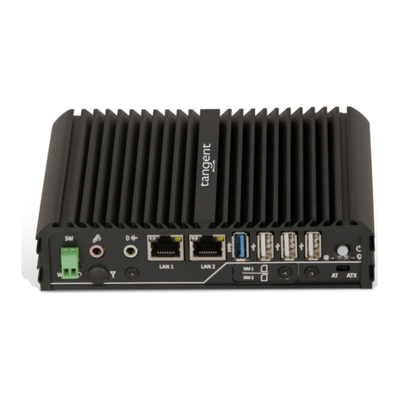
Page 10: System I/O
Rugged Mini E1 | User’s Manual Chapter 1: Product Introductions 1.3 System I/O 1.3.1 Rugged Mini E1 Front Panel LAN port ATX power on/off switch Used to connect the system to a local area Press to power-on or power-off the system... -
Page 11: Mechanical Dimension
Rugged Mini E1 | User’s Manual Chapter 1: Product Introductions 1.4 Mechanical Dimensions 1.4.1 Rugged Mini E1 Unit: mm... -
Page 12: Chapter 2 Jumpers And Connectors
Chapter 2 Switches and Connectors... -
Page 13: Switch And Connector Locations
Rugged Mini E1 | User’s Manual Chapter 2: Switches and Connectors 2.1 Switch and Connector Locations 2.1.1 Top View... -
Page 14: Bottom View
Rugged Mini E1 | User’s Manual Chapter 2: Switches and Connectors 2.1.2 Bottom View 2.1.3 Daughter board view... -
Page 15: Connector / Switch Definition
Rugged Mini E1 | User’s Manual Chapter 2: Switches and Connectors 2.2 Connector / Switch Definition List of Connector / Switch Connector Location Definition AT_ATX1 AT / ATX Power Mode Switch CLR_CMOS1 Clear BIOS Switch PWR_SW1 Power Switch PWR_LED1 Power LED Status... -
Page 16: Switch Definitions
Rugged Mini E1 | User’s Manual Chapter 2: Switches and Connectors 2.3 Switches Definitions AT_ATX1: AT / ATX Power Mode Switch Switch Definition 1-2 (Right) ATX Power Mode(Default) 2-3 (Left) AT Power Mode CLR_CMOS1: Clear BIOS Switch Switch Definition Normal Status (Default) Clear BIOS 2.4 Connectors Definitions... - Page 17 Rugged Mini E1 | User’s Manual Chapter 2: Switches and Connectors USB3_1: USB 3.0 Connector, Type A Definition Definition USB3_RX+ USB2_DATA1- USB2_DATA1+ USB3_TX- USB3_TX+ USB3_RX- LAN1, LAN2: RJ45 with LEDs Port Definition Definition LAN1_MDI0P LAN1_MDI2N LAN1_MDI0N LAN1_MDI1N LAN1_MDI1P LAN1_MDI3P LAN1_MDI2P...
- Page 18 Rugged Mini E1 | User’s Manual Chapter 2: Switches and Connectors LINE_OUT1 : Line-out Jack (Green) Connector Type: 5-pin Phone Jack Definition OUT_R OUT_L MIC_IN1: Microphone Jack (Pink) Connector Type: 5-pin Phone Jack Definition MIC_R MIC_L PWR_SW2 : Remote Power Switch Connector Type: Terminal Block 1X2 2-pin, 3.5mm pitch...
- Page 19 Rugged Mini E1 | User’s Manual Chapter 2: Switches and Connectors DVI_I1: DVI-I Connector Definition Definition DVI_TX2- DVI Hot Plug Detect DVI_TX2+ DVI_TX0- DVI_TX0+ DDC_CLOCK DDC_DATA VGA VSYNC DVI_TXCLK+ DVI_TX1- DVI_TXCLK- DVI_TX1+ VGA_RED VGA_GREEN VGA_BLUE VGA_HSYNC COM1_1: RS232 / RS422 / RS485 Connector...
- Page 20 Rugged Mini E1 | User’s Manual Chapter 2: Switches and Connectors COM2_1: RS232 / RS422 / RS485 Connector Connector Type: 9-pin D-Sub RS422 / 485 Full RS485 Half Duplex RS232 Definition Duplex Definition Definition DCD2 TX2- DATA2- RxD2 TX2+ DATA2+...
- Page 21 Rugged Mini E1 | User’s Manual Chapter 2: Switches and Connectors CN2: RS232 / RS422 / RS485 Connector Connector Type: 9-pin D-Sub RS422 / 485 Full RS485 Half Duplex RS232 Definition Duplex Definition Definition DCD4 (DCD6) TX4- (TX6-) DATA4- (DATA6-)
- Page 22 Rugged Mini E1 | User’s Manual Chapter 2: Switches and Connectors...
- Page 23 Rugged Mini E1 | User’s Manual Chapter 2: Switches and Connectors MINIPCIE1: Mini PCI-Express Socket Definition Definition Definition WAKE# +3.3V +3.3V USB_DP1 +3.3V MINIPCIE RST# MINIPCIE_RXN1 +3.3V +1.5V +3.3V CLKREQ1# MINIPCIE_RXP1 +1.5V MINIPCIE_CLKN1 SMB_CLK +1.5V MINIPCIE_CLKP1 MINIPCIE_TXN1 SMB_DATA MINIPCIE_TXP1 +3.3V...
- Page 24 Rugged Mini E1 | User’s Manual Chapter 2: Switches and Connectors SATA1: SATA with Power Connector Definition Definition SATA_TXP1 SATA_TXN1 SATA_RXN1 SATA_RXP1 +3.3V +3.3V +12V +3.3V +12V +12V...
-
Page 25: Chapter 3 Bios Setup
Chapter 3 BIOS Setup... -
Page 26: Bios Introduction
Chapter 3: BIOS Setup Rugged Mini E1 | User’s Manual 3.1 BIOS Introduction The system BIOS software is stored on EEPROM. The BIOS provides an interface to modify the configuration. When the battery is removed, all the parameters will be reset. -
Page 27: Main Setup
Rugged Mini E1 | User’s Manual Chapter 4: BIOS Setup 3.2 Main Setup Press <Del> to enter BIOS CMOS Setup Utility. The Main setup screen is showed as following when the setup utility is entered. System Date/Time is set up in the Main Menu. -
Page 28: Advanced Setup
Chapter 3: BIOS Setup Rugged Mini E1 | User’s Manual 3.3 Advanced Setup 3.3.1 ACPI Settings ■ Enable ACPI Auto Configuration This item allows you to enable or disable BIOS ACPI Auto Configuration. ■ Enable Hibernation This item allows you to enable or disable system ability to hibernate. -
Page 29: Super Io Configuration
Chapter 3: BIOS Setup Rugged Mini E1 | User’s Manual 3.3.2 Super IO Configuration This setting allows you to select options for the Super IO Configuration, and change the value of the selected option. ■ Serial Port 1 Configuration Serial Port This item allows you to enable or disable serial port. - Page 30 Chapter 3: BIOS Setup Rugged Mini E1 | User’s Manual ■ Serial Port 2 Configuration Serial Port This item allows you to enable or disable serial port. Change Settings This item allows you to change the address & IRQ settings of the specified serial port.
- Page 31 Chapter 3: BIOS Setup Rugged Mini E1 | User’s Manual ■ Serial Port 4 Configuration Serial Port This item allows you to enable or disable serial port. Change Settings This item allows you to change the address & IRQ settings of the specified serial port.
- Page 32 Rugged Mini E1 | User’s Manual Chapter 4: BIOS Setup ■ Serial Port 6 Configuration Serial Port This item allows you to enable or disable serial port. Change Settings This item allows you to change the address & IRQ settings of the specified serial port.
-
Page 33: Hardware Monitor
Rugged Mini E1 | User’s Manual Chapter 4: BIOS Setup 3.3.3 Hardware Monitor These items display the current status of all monitored hardware devices/ components such as voltages and temperatures. 3.3.4 Serial Port Console Redirection ■ Console Redirection These items allows you to enable or disable COM1~COM6 console redirection. -
Page 34: Cpu Configuration
Rugged Mini E1 | User’s Manual Chapter 4: BIOS Setup 3.3.5 CPU Configuration ■ Intel Virtualization Technology Virtualization enhanced by Intel Virtualization Technology will allow a platform to run multiple operating systems and applications in independent partitions. With virtualization, one computer system can function as multiple Virtual systems. -
Page 35: Ppm Configuration
Rugged Mini E1 | User’s Manual Chapter 4: BIOS Setup 3.3.6 PPM Configuration ■ CPU C state Report Enables or disables support for CPU's power-saving functions. ■ Enhanced C state Enables or disables Intel CPU Enhanced Halt (C1E) function, a CPU power-saving function in system halt state. -
Page 36: Sata Configuration
Chapter 3: BIOS Setup Rugged Mini E1 | User’s Manual 3.3.7 SATA Configuration ■ SATA Speed Support Change the SATA Speed. Select <Gen1> or <Gen2> speed. ■ SATA Mode This item allows you to select IDE or AHCI Mode. ■ Serial – ATA Port 0 This item allows you to enable or disable Serial-ATA Port 0. -
Page 37: Compatibility Support Module Configuration
Chapter 3: BIOS Setup Rugged Mini E1 | User’s Manual 3.3.9 CSM Configuration ■ CSM Support Enables or disables UEFI CSM (Compatibility Support Module) to support a legacy PC boot process. ■ Boot option filter This item allows you to select which type of operating system to boot. -
Page 38: Usb Configuration
Chapter 3: BIOS Setup Rugged Mini E1 | User’s Manual 3.3.10 USB Configuration ■ Legacy USB Support Allows USB keyboard/ mouse to be used in MS-DOS. ■ XHCI Hand-off Determines whether to enable XHCI (USB3.0) Hand-off feature for an operating system without XHCI (USB3.0) Hand-off support. -
Page 39: Chipset
Chapter 3: BIOS Setup Rugged Mini E1 | User’s Manual 3.4 Chipset 3.4.1 North Bridge This section provides information on the installed memory size and memory/onboard graphics-related configuration options. - Page 40 Rugged Mini E1 | User’s Manual Chapter 3: BIOS Setup ■ Intel IGD Configuration This section provides onboard graphics-related configuration options. IGD Turbo Enable This item allows you to enable or disable IGD Turbo. GFX Boost This item allows you to enable or disable GFX Boost.
-
Page 41: South Bridge
Rugged Mini E1 | User’s Manual Chapter 3: BIOS Setup 3.4.2 South Bridge ■ Azalia HD Audio Control detection of the Azaliadevice. Audio Controller Enabled: Azalia will be unconditionally enabled. Disabled: Azalia will be unconditionally disabled. ■ USB Configuration ... - Page 42 Rugged Mini E1 | User’s Manual Chapter 3: BIOS Setup ■ PCI Express Configuration PCI Express Port 1 (mPCIE1) This item allows you to enable or disable PCI Express Port 1 (mPCIE1) in the Chipset. Speed Change the PCIe Port Speed. Select <AUTO> ,<Gen 2> or <Gen 1>...
-
Page 43: Security
Rugged Mini E1 | User’s Manual Chapter 3: BIOS Setup 3.5 Security Security menu allow you to change administrator password and user password settings. 3.5.1 Administrator Password This item allows you to set Administrator Password. 3.5.2 User Password This item allows you to set User Password. -
Page 44: Boot
Rugged Mini E1 | User’s Manual Chapter 3: BIOS Setup 3.6 Boot This menu allows you to setup the system boot options. 3.6.1 Setup Prompt Timeout This item sets number of seconds to wait for setup activation key. 3.6.2 Bootup NumLock State This item selects the keyboard NumLock state. -
Page 45: Save & Exit
Rugged Mini E1 | User’s Manual Chapter 3: BIOS Setup 3.7 Save & Exit This setting allows you to configure the boot settings. 3.7.1 Save Changes and Reset This item allows you reset the system after saving the changes. 3.7.2 Discard Changes and Reset Select this option to quit Setup without making any permanent changes to the system configuration. -
Page 46: Appendix Wdt & Gpio
Appendix WDT & GPIO This appendix provides the sample codes of WDT (Watch Dog Timer) and GPIO (General Purpose Input/ Output). -
Page 47: Gpio Sample Code
Rugged Mini E1 | User’s Manual Appendix – WDT & GPIO WDT Sample Code SIO_INDEX_Port equ 04Eh SIO_DATA_Port equ 04Fh SIO_UnLock_Value equ 087h SIO_Lock_Value equ 0AAh WatchDog_LDN equ 007h WDT_UNIT equ 60h ;60h=second, 68h=minute, 40h=Disabled Watchdog timer WDT_Timer equ 30 ;ex. - Page 48 Rugged Mini E1 | User’s Manual Appendix – WDT & GPIO GPIO Sample Code GPI 0 ~ GPI 3 GPI 0 GPI 1 GPI 2 GPI 3 IO Address 0xA03h 0xA03h 0xA03h 0xA03h Sample code GPO 0 ~ GPO 3...
- Page 49 Copyright © Tangent Inc. All Rights Reserved www.tangent.com...
Need help?
Do you have a question about the Rugged Mini E1 and is the answer not in the manual?
Questions and answers