
Related Manuals for A.M.P.I. Master-8


Summary of Contents for A.M.P.I. Master-8
- Page 1 Master-8 EIGHT CHANNEL PROGRAMMABLE PULSE STIMULATOR Operation Manual 123 Uziel St., P .O.B. 16477 Jerusalem 91163, ISRAEL phone: +972 2 643-9338 fax: +972 2 643-1833 e-mail: info@ampi.co.il A.M.P.I. http://www.ampi.co.il...
-
Page 2: Table Of Contents
You will find that Master-8 is user friendly and the programming simple and easy to learn. Master-8 is an attractive unit and you will enjoy using it. Please read this manual carefully and become familiar with all the possible options and operating modes. - Page 3 ..............14.4 Master-8 SDK (Software Development Kit)
-
Page 4: Introduction
The Master-8-cp and Master-8-vp models can operate as stand alone units via the front panel keys in the same way as Master-8. In addition they can communicate with a PC. The communication with a PC can be performed in the following ways: 1) Using the Master-8 Control Software. -
Page 5: Front And Rear Panel Description
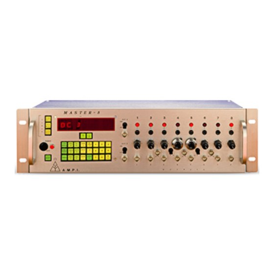
2. Front & Rear Panel Description DC 3 Figure 1 Front Panel The Front Panel contains five sections (see Figure 1): A- Power Switch and Power On Indicator B- Front Panel keys C- Digital Display D- External Trigger Input Section E- Output Section Power Switch and Power On Indicator (Figure 1A) The Power Switch and the Power On Indicator are located on the left side of... -
Page 6: Rear Panel
The rear panel contains the following components: A switch to connect or disconnect the ground to/from the chassis. You can use this switch to reduce the noise level of the system. A USB interface to communicate with a computer (for the Master-8-cp and Master-8-vp models). -
Page 7: Theory Of Operation
Channels 1 and 2 can receive external triggers. This enables synchronizing channels with external devices. Master-8 features a clock which measures the time that has elapsed after pressing the CLOCK-RESET key (e.g. the experiment time). It also features a timer which can change the operational mode of a channel at a certain hour (e.g. -
Page 8: Operation
4. Operation Master-8 is simple to operate and can be learned in a short time. Each instruction is carried out only after pressing the ENTER key. As long as the ENTER key has not been pressed, the instruction can be changed or deleted by giving new instructions (e.g. -
Page 9: Applications
5. Applications Figure 3 shows you how Master-8 works. Do not try to follow the programming yet, Section 6 will enable you to practice programming the Master-8. interval duration Channel 3 FREE RUN ① delay Channel 2 TRIG triggered by #3... - Page 10 A special feature of Master-8 is the 3 multilevel outputs which you can use for multilevel pulses (e.g. biphasic pulses). These outputs are ‘2+3’, ‘4+5’ and ‘6+7+8’ (Figures 1F,1G & 1H), which deliver the summation of outputs 2+3, 4+5 and 6+7+8 respectively. Using the two switches (Figures 1K & 1L) you can add the summations ‘2+3’...
-
Page 11: Demonstration Of Programming Master-8
2. Before continuing, make sure that you are familiar with the location of different keys (see Section 2.1). Before you begin to program, the entire Master-8 memory must be cleared. Press keys: ‘OFF, ALL, ALL, ALL, ENTER’ (see Section 11). - Page 12 Set channel #2 to the TRIGGER mode (see Section 7). Press keys: ‘TRIG, 2, ENTER’ . Nothing happens since channel #2 is now in the TRIGGER mode, but is waiting to accept a trigger. You can trigger it in 3 ways (see Section 9): a) MANUAL TRIGGERING - Press key: ‘2’.
- Page 13 - your present experiment (paradigm), and now you want to switch to a new pattern that also uses all the 8 channels. With Master-8 this is an easy process, but you are first required to set the other paradigm.
- Page 14 Dear User, The last section was a brief demonstration of how to use Master-8. Now you have a rough idea of how Master-8 works. However, here are many instructions that you are not yet familiar with e.g. DC, GATE, CHECK, TIMER.
-
Page 15: Modes Of Operation
7. Modes of Operation Each of the 8 channels can operate in one of the following modes: Mode Description Parameters in Use FREE - RUN The channel delivers pulses Duration, Interval continuously according to the programmed duration and interval times. The channel is independent of the other channels. - Page 16 Example 2: To set channel #3 to the TRAIN mode - Press keys: ‘TRAIN, 3, ENTER’. Channel #3 is now in the TRAIN mode. You can trigger it in several ways (see Section 9). Trigger it now manually by pressing ‘3’ (the channel number). Example 3: To set channel #5 to the DC mode - Press keys: ‘DC, 5, ENTER’.
-
Page 17: Setting Parameters
8. Setting Parameters To set the time parameters (DURA, DELAY or INTER), first press the selected parameter key and then the desired time. Example: To set the duration of channel 6 to be 52 msec (52 x 10 sec, the time is given in seconds). -
Page 18: Counting The Pulses
Counting the Pulses Whenever channel 8 is in the TRAIN mode, the display shows how many pulses still remain in the existing train. Press keys: ‘TRAIN, 8, ENTER’. Now trigger channel 8 manually - Press key: ‘8’. Table 1 - Parameters and Error Indication Parameter Error indication for illegal values. -
Page 19: Triggering
9. Triggering In either TRAIN or TRIG mode you can trigger the channel in the following ways: 1. Manually 2. The internal connections 3. The external inputs EXT 1 and EXT 2 Manual Triggering In the TRAIN, TRIG or DC modes you can trigger the channel manually by pressing the channel number. -
Page 20: External Inputs
2. (channels 1 and 2 can activate the other channels internally). The external input has to be in the range of 5 to 10V. Note: A computer can trigger each channel directly ‘manually’ via the USB interface of Master-8-cp (see Section 14). -
Page 21: Eight Stored Paradigms
10. Eight Stored Paradigms A paradigm specifies the modes and parameters of all the channels and their internal connections. Master-8 stores eight different programmed paradigms. 10.1 Switching to Another Paradigm Example: To switch to paradigm number 7 - Press key: ‘ALL’ (the present paradigm number is displayed) ‘7, ENTER’. -
Page 22: Clearing The Memory
Clearing the present paradigm does not affect the other paradigms, the clock, the stop-watch and the timer. To clear all the memory of all the 8 paradigms (Master-8 will then be without any user program) - Press keys: ‘OFF, ALL, ALL, ALL, ENTER’. -
Page 23: Verification Checks
12. Verification Checks There are many details you can check. Note: All the checking instructions begin with the word ‘CHECK’. To check the modes of all the channels - Press keys: ‘CHECK, ENTER’. The display shows the modes of all the channels that are not turned off and the present paradigm number. -
Page 24: Clock Options
13. Clock Options In addition to its standard 8 channels, Master-8 features 2 internal clocks. The first is called ‘clock’ and counts the time in seconds up to 24 hours. The other called ‘stop-watch’ counts the time in tenths of seconds up to 1 hour. -
Page 26: Master-8 Sdk (Software Development Kit)
14.4 Master-8 SDK (Software Development Kit) The SDK is a set of files which enables Master-8-cp to be connected to other software and programming tools. Using the SDK you can control the Master-8-cp via a variety of... - Page 28 123 Uziel St., P .O.B. 16477 Jerusalem 91163, ISRAEL phone: +972 2 643-9338 fax: +972 2 643-1833 e-mail: info@ampi.co.il A.M.P.I. http://www.ampi.co.il...
Need help?
Do you have a question about the Master-8 and is the answer not in the manual?
Questions and answers