Table of Contents
Advertisement
Quick Links
Advertisement
Table of Contents

Related Manuals for AnyTone 518UV II


Summary of Contents for AnyTone 518UV II
- Page 2 518UV INSTRUCTION MANUAL...
- Page 4 THANK YOU! transceiver will provide you with reliable, clear and efficient communication service. The transceiver introduces innovative DSP digital signal processing technology, high degree integration, it is including kinds of professional function, best stability and great reliability as well as exterior smooth lines, novel, fashionable, sturdy and durable.
- Page 5 CAUTIONS transceiver is excellent designed with advanced technology. The following tips will be helpful for you in performing your obligation under warranty and understanding the safety of transceiver usage. 1.Keep the transceiver and accessories away from children. 2.Please do not try to open or modify the transceiver without permission, non-professionals operation may also cause damage.
-
Page 6: Table Of Contents
TABLE OF CONTENTS UNPACKING ........................................ 01 Supplied Accessories ..................................01 STANDARD ACCESSORIES/ADDITIONAL ACCESSORIES ................02 Standard Accessories ..................................02 Additional Accessories ..................................02 BATTERY INFORMATION ................................. 03 Charging Operation ....................................03 Battery Charger Type ................................... 03 Notice for Charging Battery ................................ - Page 7 TABLE OF CONTENTS Receiving ........................................13 Transmitting ......................................13 Emergency Alarm ....................................14 Side Key [PF1] function instruction ............................... 14 Side key [PF2] function instruction ..............................15 Edit channel ......................................15 Delete channel ......................................15 Programming scan ....................................16 Turn On/Off FM Radio ..................................
-
Page 8: Unpacking
UNPACKING Please carefully unpack the transceiver. We recommend that you identify the items listed in the following table before discarding the packing material. If any items are missing or have been damaged during shipment, please contact with dealers immediately. Supplied Accessories Item Number Quantity... -
Page 9: Standard Accessories/Additional Accessories
STANDARD ACCESSORIES/ADDITIONAL ACCESSORIES Standard Accessories Antenna* Li-ion Battery Battery Charger Belt Clip Instruction AC Adaptor QPS-07 Manual QA11UV QB-40L QBC-40L BC09 155/435MHz *1.Note: For frequency band of antenna, please refer to label indicated in the bottom of the antenna. Additional Accessories USB Programming Programming Software Earphone... -
Page 10: Battery Information
BATTERY INFORMATION Charging Operation The battery is not charged at the factory, please charge it before use. Charge the battery for the first time after purchase or extended storage (more than 2 months) may not bring the battery to its normal operating capacity. -
Page 11: How To Charge
BATTERY INFORMATION ▲ Do not recharge the battery if it is already fully charged. This may shorten the life of the battery or damage the battery. ▲ Do not charge the battery or transceiver if it is damp. Dry it before charging to avoid danger. WARNING: When keys or ornamental chains and other electric metals contact with the battery terminals, the battery may cause damage or hurt bodies. - Page 12 BATTERY INFORMATION NOTE: When charging a power-on transceiver equipped with battery, the LED will not turn into green to show the full charge status. Only when turn off the transceiver, the LED can indicate normally. Because when the transceiver is power on, it would consumes energy, the charger cannot detect when battery has been fully charged, the charger will charge battery in voltage consumption and fail to indicate correctly.
-
Page 13: Charging Prompt
BATTERY INFORMATION Charging Prompt 1.Self-examination: When charging, ORANGE light twinkles for 1 second and goes out. That means the charger has passed its self-examination and it can charge the battery normally. If the light remains orange or the red light twinkles, which means the charger can not pass its self-examination or charge the battery. -
Page 14: Getting Acquainted
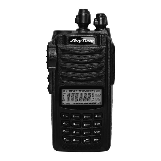
GETTING ACQUAINTED LCD Display On LCD display screen, you will see various icons which stand for the selected functions and sometimes you may forget the meaning of them. Here you will find the following table extremely useful. Frequency VOX Function Reverse Offset Frequency Scan Skip... - Page 15 GETTING ACQUAINTED...
- Page 16 GETTING ACQUAINTED Antenna Selector Knob Power / Volume Switch Rotate it clockwise to turn on transceiver, rotate it anticlockwise until heard "click" to turn off the transceiver. When transceiver is power on, rotate it clockwise to increase volume, anticlockwise to reduce volume. TX/RX indicator, RX is GREEN, TX is RED LCD display Displays current frequency/channel and operations...
-
Page 17: Basic Operations
BASIC OPERATIONS Turn the Radio On & OFF Under power-off state, please turn [POWER]/[VOLUME] clockwise to turn on the transceiver. Under power-on state, please turn [POWER]/[VOLUME] anticlockwise to turn off the transceiver. Adjusting Volume Under power-on state, turn [POWER] /[VOLUME] to adjust volume. Clockwise-up, anticlockwise -down. -
Page 18: Switch Between Main Band And Sub Band
BASIC OPERATIONS Switch between Main band and Sub band Under standby state, press key to switch channel between Main band and Sub band. Arrow directs the current operational channel. Switch between Channel mode Under standby state, press key to set main band as Channel mode Channel Adjusting When transceiver in Channel mode or FM radio channel mode, rotate channel switch to adjust channel. -
Page 19: Frequency Input By Keypad
BASIC OPERATIONS NOTE: Channel step:2.5K) 5K) 6.25K) 10K) 12.5K) 20K) 25K) 30K and 50KHz in total 9 for optional. FM radio step frequency is 50K. Channel Input by Keypad Under channel mode of transceiver or FM radio, you can switch to desired channel by entering three numbers (001-199). -
Page 20: Fm Channel Searching
BASIC OPERATIONS FM Channel Searching When transceiver in FM radio mode, press key, LCD displays " " icon, then press to start FM searching. When one station is sought, LCD displays current station frequency, you can listen to current station. Squelch Off Momentary / Squelch Off Side key [PF2] can be setup for Squelch off Momentary or Squelch off function by programming software. -
Page 21: Emergency Alarm
BASIC OPERATIONS it is not busy, press [PTT] key and talk to speaker. Please keep the distance between mouth and speaker to be 2.5-5CM, speak in normal tone to get the best acoustic fidelity. NOTE: When press and hold PTT key, transceiver is transmitting if the red LED light is on, release [PTT] key to receive calls. -
Page 22: Side Key [Pf2] Function Instruction
BASIC OPERATIONS Switch between Main band and Sub band Under standby state, press key to switch channel between Main band and Sub band. Arrow directs the current operational channel. Switch between Channel mode Under standby state, press key to set main band as Channel mode Channel Adjusting When transceiver in Channel mode or FM radio channel mode, rotate channel switch to adjust channel. -
Page 23: Programming Scan
BASIC OPERATIONS switch into channel mode, channel number flashes. 2. Rotate channel switch to select desired deleting channel number. 3. Press key, the top left corner of LCD displays " " icon, press and hold key until transceiver emits "DUDU" beep and clear up frequency information of current channel, deletion is successful. NOTE: This process can be applied for deleting FM radio channels. -
Page 24: Turn On/Off Fm Radio
BASIC OPERATIONS Turn On/ Off FM Radio Under standby state, press key, the top left corner of LCD displays " " icon, then press key, LCD displays "FM ON" and current FM radio frequency, FM radio function is on. When FM radio is on, press key, LCD displays "FM OFF", FM radio is mute. -
Page 25: Offset Frequency Direction Setup
BASIC OPERATIONS DCS signaling, it will stay 5seconds and then go on scanning. Press any other keys except key to exit. NOTE: This function is invalid when transceiver works in professional mode or the arrow directed channel no setting CTCSS/DCS signaling. In current channel, if signaling set as CTCSS, it will scan CTCSS, if sets as DCS, will scan DCS. -
Page 26: Frequency/Channel Scan
BASIC OPERATIONS Channel Scan Under corresponding mode, press key, the top left corner of LCD displays " " icon, then press key to start frequency scan or channel scan. 1. Channel Scan Under channel mode, this function is used for monitoring signal of each channel in this mode. -
Page 27: Frequency Reverse
BASIC OPERATIONS 1. LCD displayed " " means the current channel will not be scanned. 2. " " icon disappeared means the current channel will be scanned. Frequency Reverse Under standby state, press key, the top left corner of LCD displays " "... -
Page 28: Dtmf Code Transmit And Enquiry
BASIC OPERATIONS 3. Press [PF1], [PF2] or key to exit stop watch function. NOTE: During timing, press key to stop timing and displays current data, press this key again to clear timer. DTMF code Transmit and Enquiry 1. Press key, the top left corner of LCD displays " "... -
Page 29: Single-Band Switching
BASIC OPERATIONS Single-band Switching To avoid interference from the sub channels when main channel in use, you can use the single band switching function to turn off sub channel band quickly. 1. In standby mode, press key, the radio will display the upper band, the lower band will be turned off. -
Page 30: Function Menu Setup
FUNCTION MENU SETUP Menu 1-13 of this transceiver are channel operations. Channel operations temporarily changed the functions of current channel. When power off or channel has been changed, the relevant setup will be erased. The operating methods are as follows: 1. - Page 31 FUNCTION MENU SETUP No CTCSS/DCS encode/decode CTCSS/DCS 51 groups fixed CTCSS encode/decode + 1 group 62.5HZ-254.1Hz+Self defined RT-CDC Encode/Decode self-defined CTCSS encode/decode Synchronous 000N-777I 1024 group DCS encode/decode Optional signaling TONDEC DTMF Current optional signal is DTMF. setup When current channel received matching RF signals, transceiver can hear the talking from the other party.
- Page 32 FUNCTION MENU SETUP Wide / Narrow 25K/12.5K Wide band/Narrow band Band Selection Turn on Frequency reverse function, TX and RX Frequency frequency of current channel will be interchanged. Reverse Close Frequency reverse function. Turn on Talk Around function, current channel will transmit at RX frequency, if CTCSS/DCS signaling TX=RX is set, it will interchange decoding CTCSS/DCS as...
- Page 33 FUNCTION MENU SETUP FREQ Display sub band frequency or channel Sub band display DSPSUB VOLT Display current battery voltage setup Sub band display is disabled Keypad Voice BEEP ON/OFF Turn on/off keypad voice prompt function prompt setup Turn off time-out timer Time-Out-Timer Total 27 levels of TOT for optional, each interval is 10-270S...
- Page 34 FUNCTION MENU SETUP When finished function setting or enter into FUNCT function menu, icon disappeared. Function Icon When finished function setting or enter into function FTIME 1SEC-3SEC menu, icon stay 1-3seconds then disappeared. Stay Time Function icon is always display, only when pressing ALWAYS function key again, the icon will disappear.
-
Page 35: Display Mode Setup
FUNCTION MENU SETUP Display Mode Setup There are three kinds of display modes for optional. 1. Press [PF2] key to turn on radio, hold [PF2] key until transceiver emits beep. 2. Press key to choose No. 01 function item, it shows "DSP" on LCD. 3. - Page 36 FUNCTION MENU SETUP OFF: No operations. FACT: Resume all items to factory default, including channel and background settings. INIT: Resume background settings to factory default, channel operations are keeping. 4. Press key to exit current selection. 5. Press key to confi rm current selection. Note: In power off state, hold key to power on radio, the radio will resume to factory default.
-
Page 37: Technical Specification
TECHNICAL SPECIFICATION General Receiving Part VHF: 136~174MHz Wide band Narrow band Frequency Range UHF: 400~480MHZ Sensitivity ( EX: 400~520MHz) ≤0.25μV ≤0.35μV (12dB SINAD) Channel Capacity 200 channels Adjacent Channel 25KHz (wide band) ≥65dB ≥60dB Channel Spacing Selecitvity 12.5KHz (narrow band) Intermodulation ≥60dB ≥60dB... -
Page 38: Trouble Shooting Guide
TROUBLE SHOOTING GUIDE Problem Corrective Action A.The battery may be exhausting. Recharge or replace the battery. No power B.The battery may not be installed correctly. Remove the battery and install it again. Battery power dies shortly after The battery life is finished. Replace the battery pack with a new one. charging. - Page 39 The SAR limit of USA (FCC) is 8 W/kg averaged over one gram of tissue. Device types 518UVII (FCC ID: T4K3208UV) has also been tested against this SAR limit. The highest SAR value reported under this standard during product certification for use when properly worn on the body is 2.366 W/kg and for head is 3.990 W/kg.
Need help?
Do you have a question about the 518UV II and is the answer not in the manual?
Questions and answers