Table of Contents
Advertisement
Quick Links
Thank you for purchasing the Mitsubishi programmable controller
MELSEC-Q series.
Prior to use, please read this and relevant manuals thorougly to fully
understand the product.
© 2007 MITSUBISHI ELECTRIC CORPORATION
High-Speed Counter
MODEL
MODEL
CODE
IB(NA)-0800387-B(0808)MEE
Multichannel
Module
User's Manual
QD63P6
QD63P6-U-HW
13JY33
(Hardware)
Advertisement
Table of Contents

Related Manuals for Mitsubishi Melsec-Q QD63P6-U-HW


Summary of Contents for Mitsubishi Melsec-Q QD63P6-U-HW
- Page 1 Multichannel High-Speed Counter Module User’s Manual (Hardware) QD63P6 Thank you for purchasing the Mitsubishi programmable controller MELSEC-Q series. Prior to use, please read this and relevant manuals thorougly to fully understand the product. MODEL QD63P6-U-HW MODEL 13JY33 CODE IB(NA)-0800387-B(0808)MEE © 2007 MITSUBISHI ELECTRIC CORPORATION...
- Page 2 SAFETY PRECAUTIONS (Always read these instructions before using this equipment.) Before using this product, please read this manual and the relevant manuals introduced in this manual carefully and pay full attention to safety to handle the product correctly. The instructions given in this manual are concerned with this product. For the safety instructions of the programmable controller system, please read the User’s Manual for the CPU module.
- Page 3 [Installation Precautions] CAUTION Use the programmable controller in the environment conditions given in the general specifications of the User's Manual for the CPU module. Using this programmable controller in an environment outside the range of the general specifications could result in electric shock, fire, erroneous operation, and damage to or deterioration of the product.
- Page 4 [Wiring Precautions] CAUTION When wiring/connecting the connector, properly press, crimp or solder the connector using the tools specified by the manufactures and attach the connector to the module securely. Be sure there are no foreign substances such as sawdust or wiring debris inside the module.
- Page 5 This manual confers no industrial property rights or any rights of any other kind, nor does it confer any licenses. Mitsubishi Electric Corporation cannot be held responsible for any problems involving industrial property rights which may occur as a result of using the contents noted in this manual.
-
Page 6: Table Of Contents
CONTENTS 1. OVERVIEW..................... 1 2. PERFORMANCE SPECIFICATIONS ............. 2 3. IMPLEMENTATION AND INSTALLATION............4 3.1 Handling Precautions ................4 3.2 Installation Environment ................4 4. PART NAMES....................5 5. EXTERNAL WIRING ..................6 5.1 Wiring Precautions ................... 6 5.2 External Wiring ..................7 5.3 Intelligent Function Module Switch Settings ........... - Page 7 (1) For programmable controller system To configure a system meeting the requirements of the EMC and Low Voltage Directives when incorporating the Mitsubishi programmable controller (EMC and Low Voltage Directives compliant) into other machinery or equipment, refer to Chapter 9 "EMC AND LOW VOLTAGE DIRECTIVES"...
-
Page 8: Overview
1. OVERVIEW This manual describes the specifications and part for the type QD63P6 multichannel high-speed counter module (hereinafter abbreviated as QD63P6) that is used together with the MELSEC-Q series CPU module. -
Page 9: Performance Specifications
2. PERFORMANCE SPECIFICATIONS The following table shows the performance specifications of the QD63P6. Table 2.1 Performance specifications Model Item QD63P6 Counting speed switch 200 k 100 k 10 k setting (100 k to 200 kPPS) (10 k to 100 kPPS) (10 kPPS or less) Number of occupied 32 points (I/O assignment: Intelligent 32 points) - Page 10 Table 2.2 Relation between rise/fall time and counting speed Counting speed 200 k 100 k 10 k switch setting Rise/fall time Both 1 and 2-phase input t = 1.25 s or less 200 kPPS 100 kPPS 10 kPPS t = 2.5 s or less 100 kPPS 100 kPPS 10 kPPS...
-
Page 11: Implementation And Installation
3. IMPLEMENTATION AND INSTALLATION 3.1 Handling Precautions The following explains the precautions for handling the module. (1) Do not drop the module case and/or connector or apply a strong impact to it. (2) Do not remove the printed-circuit board of the module from the case. -
Page 12: Part Names
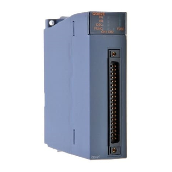
4. PART NAMES The following explains the part names of the QD63P6. Table 4.1 Part names LED name Description Indicates operation status of the QD63P6. ON: Normal operation OFF: Watchdog timer error (Connector (Connector terminal terminal Indicates error status of the QD63P6. number) number) ERR. -
Page 13: External Wiring
(6) To conform the wiring to the EMC and Low Voltage Directives, ground the shielded twisted pair cables to a control panel with the AD75CK cable clamp (manufactured by Mitsubishi Electric Corporation). In a control panel 20cm (7.87inch) -
Page 14: External Wiring
5.2 External Wiring Example of wiring the module and an encoder (1) Example of wiring with an encoder of open collector output type (5 VDC) QD63P6 Encoder Phase A Phase A Shielded pulse input + twisted pair cable Phase A pulse input - Shield 240 1/8W... - Page 15 (2) Example of wiring with an encoder of open collector output type (12/24 VDC) Load resistance 12 V 820 1/4W QD63P6 Encoder 24 V 2200 1/2W Phase A Phase A Shielded pulse input + 12/24 V twisted pair cable Phase A pulse input - Shield 240 1/8W...
- Page 16 POINT When wiring the QD63P6 and an encoder, separate the power supply cable and signal line. The following diagram shows an example of wiring with Phase A (Wire Phase B as well). [Wiring Shielded QD63P6 twisted pair cable example] Pulse input - Phase A Pulse...
- Page 17 (3) Example of wiring with an encoder of voltage output type (5 VDC) QD63P6 Encoder Phase A Shielded pulse input + Phase A twisted pair cable Phase A pulse input - Shield 240 1/8W Phase B Phase B pulse input + Shielded twisted pair cable Phase B...
-
Page 18: Intelligent Function Module Switch Settings
5.3 Intelligent Function Module Switch Settings The switch setting is made on the [I/O assignment] screen of GX Developer. Table 5.3 Intelligent function module switch Setting item Setting value Default Pulse input mode Pulse input mode : 1 multiple of 1 phase : 2 multiples of 1 phase Switch 1 0000... -
Page 19: External Dimensions
6. EXTERNAL DIMENSIONS (0.92) 90 (3.54) 27.4 (1.08) Unit: mm (inch) Figure 6.1 External dimensions... - Page 20 Warranty Mitsubishi will not be held liable for damage caused by factors found not to be the cause of Mitsubishi; machine damage or lost profits caused by faults in the Mitsubishi products; damage, secondary damage, accident compensation caused by special factors unpredictable by Mitsubishi;...