Table of Contents
Advertisement
Quick Links
Web Server Module
Thank you for purchasing the Mitsubishi programmable controller
MELSEC-Q Series.
Prior to use, please read both this manual and detailed manual
thoroughly to fully understand the product.
©2002 MITSUBISHI ELECTRIC CORPORATION
User's Manual
QJ71WS96
MODEL QJ71WS96-U-HW-JE
MODEL
CODE
IB(NA)-0800231-F(0903)MEE
(Hardware)
13JT97
Advertisement
Table of Contents

Subscribe to Our Youtube Channel
Related Manuals for Mitsubishi QJ71WS96 Series


Summary of Contents for Mitsubishi QJ71WS96 Series
- Page 1 Web Server Module User's Manual (Hardware) QJ71WS96 Thank you for purchasing the Mitsubishi programmable controller MELSEC-Q Series. Prior to use, please read both this manual and detailed manual thoroughly to fully understand the product. MODEL QJ71WS96-U-HW-JE MODEL 13JT97 CODE IB(NA)-0800231-F(0903)MEE...
-
Page 2: Safety Precautions
SAFETY PRECAUTIONS (Always read these instructions before using this equipment.) Before using this product, please read this manual and the relevant manuals introduced in this manual carefully and pay full attention to safety to handle the product correctly. Note that these instructions apply only to this product. Refer to the user's manual of the CPU module for the programmable controller system safety instructions. - Page 3 [Design Precautions] CAUTION Do not bunch the control wires or communication cables with the main circuit or power wires, or install them close to each other. They should be installed 100 mm (3.94 inch) or more from each other. Not doing so could result in noise that would cause erroneous operation. Do not power off a station where this module is mounted and do not reset the programmable controller CPU while storing the settings into the standard ROM of the module using a Web browser.
-
Page 4: Wiring Precautions
[Wiring Precautions] CAUTION Be sure to fix communication cables and power cables to the module by ducts or clamps. Failure to do so may cause damage of the module or the cables due to accidental pull or unintentional shifting of the cable, or malfunctions due to poor contact of the cables. - Page 5 This manual confers no industrial property rights or any rights of any other kind, nor does it confer any patent licenses. Mitsubishi Electric Corporation cannot be held responsible for any problems involving industrial property rights which may occur as a result of using the contents noted in this manual.
-
Page 6: Table Of Contents
CONTENTS 1. Overview......................1 2. Performance Specifications ................2 3. Mounting and Installation ................3 3.1 Handling Precautions ................3 3.2 Installation Environment ................3 4. Part Names....................4 5.External Wiring ....................6 5.1 Connecting to the 10BASE-T/100BASE-TX ..........6 5.2 Connecting to the RS-232 ................ - Page 7 (1) For programmable controller system To configure a system meeting the requirements of the EMC and Low Voltage Directives when incorporating the Mitsubishi programmable controller (EMC and Low Voltage Directives compliant) into other machinery or equipment, refer to Chapter 9 "EMC AND LOW VOLTAGE DIRECTIVES"...
-
Page 8: Overview
1. Overview This manual explains how to install the QJ71WS96 Web server module (hereinafter referred to as Web server module) and how to wire them with other devices. (Packing list) Model name Product name Quantity QJ71WS96 Web server module QJ71WS96 Battery (Q6BAT) -
Page 9: Performance Specifications
2. Performance Specifications The following describes the performance specifications of the Web server module. For the general specifications of the Web server module, refer to the user's manual of the CPU module used. Item Specifications 10BASE-T/100BASE-TX Interface (*1) 10BASE-T 100BASE-TX Data transmission speed 10Mbps 100Mbps... -
Page 10: Mounting And Installation
3. Mounting and Installation 3.1 Handling Precautions (1) Do not drop or apply severe shock to the module case since it is made of resin. (2) Before touching the module, always touch grounded metal, etc. to discharge static electricity from human body, etc. Not doing so can cause the module to fail or malfunction. -
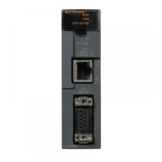
Page 11: Part Names
4. Part Names [When LED cover is closed] [When LED cover is opened]... - Page 12 Name Description 1) LED Display Refer (1) LED display. Used for connecting Web server module to 10BASE-T/ 10BASE-T/100BASE-TX. 100BASE-TX interface (Web server module recognizes 10BASE-T/ connector (RJ45) 100BASE-TX according to the external device.) RS-232 interface Used for connecting Web server module to connector RS-232.
-
Page 13: External Wiring
5. External Wiring 5.1 Connecting to the 10BASE-T/100BASE-TX Use the twisted pair cable that meets IEEE802.3 10BASE-T/100BASE-TX standards when connecting to the 10BASE-T/100BASE-TX interface. (1) For 100Mbps Use either of the following cables. (a) Unshielded twisted pair cable (UTP cable), Category 5 (b) Shielded twisted pair cable (STP cable), Category 5 (2) For 10Mbps Use either of the following cables. -
Page 14: Connecting To The Rs-232
5.2 Connecting to the RS-232 Use the RS-232 cable when connecting to the RS-232 interface. (1) RS-232 connector specifications Signal direction Signal Signal name Web server module abbreviation Modem CD(DCD) Data Carrier Detect RD(RXD) Received Data SD(TXD) Transmitted Data ER(DTR) Data Terminal Ready SG(GND) Signal Ground... -
Page 15: Setting From Gx Developer
6. Setting from GX Developer Set the mode, default operation, battery error detection, logging monitor and response monitoring time for Web server module on the "Intelligent function module switch setting" screen. Item Description Switch 1 Mode setting Default operation setting/Battery error detection Switch 2 setting/Logging monitor setting Switch 3 (lower byte) - Page 16 1: Displays the latest file update time. 1: Operates according to the default setting. User name : QJ71WS96 Battery error detection setting Password : MITSUBISHI 0: Detects battery error. Access authority : 1: Not detect battery error. Device write/Tag component write/...
- Page 17 (c) Logging monitor setting (bit 4) Whether the latest file update time is displayed or not in the file specification field of the logging monitor is set in this setting. 0: Not display the latest file update time. 1: Displays the latest file update time. (3) Response monitoring time setting (switch 3 (lower byte)) This is the setting for timeout time (second) from when a module sends a request to the CPU of the accessed device until the CPU responds to it.
-
Page 18: External Dimensions
7. External Dimensions (*1) (0.91) 90 (3.54) 27.4 (1.08) Cable's outside diameter 4 + 10 (*2) (Unit:mm (in.)) *1: The bending radius near the connectors (reference value: R1) should be four times as long as the cable's outside diameter or more when connecting the twisted pair cable. -
Page 19: Transportation Precautions
8.2 Transport Guidelines Comply with IATA Dangerous Goods Regulations, IMDG code and the local transport regulations when transporting products after unpacking or repacking, while Mitsubishi ships products with packages to comply with the transport regulations. Please consult your carrier for further details. - Page 20 Warranty Mitsubishi will not be held liable for damage caused by factors found not to be the cause of Mitsubishi; machine damage or lost profits caused by faults in the Mitsubishi products; damage, secondary damage, accident compensation caused by special factors unpredictable by Mitsubishi;...
Need help?
Do you have a question about the QJ71WS96 Series and is the answer not in the manual?
Questions and answers