Table of Contents
Advertisement
Advertisement
Table of Contents

Related Manuals for Aqua Lung BC 1


Summary of Contents for Aqua Lung BC 1
- Page 1 BC 1 Buoyancy Compensator User's Manual Rev. 03/16...
- Page 2 Aqua Lung America, Inc. ©2016 Aqua Lung International BC 1 User’s Manual PN 18562 You can contact a Technical Advisor via e-mail at: sreilly@aqualung.com grubin@aqualung.com jbutner@aqualung.com...
-
Page 3: Table Of Contents
TABLE OF CONTENTS General Precautions and Warnings .........4 BC 1 Components ..............7 Product Description ..............8 Basic Set-up ................8 Donning and Adjustment Procedures ........16 Weight Integration Features ...........19 Inflation Methods ..............26 Deflation Methods ..............27 Buoyancy and Cylinder Capabilities ........29 Pre-Dive Inspection ..............31 Post-Dive Care and Maintenance ...........32... -
Page 4: General Precautions And Warnings
GENERAL PRECAUTIONS AND WARNINGS This manual provides essential instruction for the proper fitting, adjustment, inspection and care of your new BC. Because Aqua Lung is utilizing patented BC technology, it is very important to take the time to read these instructions in order to understand and fully enjoy the features that are unique to your specific model. - Page 5 This BC is designed for use with compressed air or Nitrox/EAN (enriched air nitrox) mixtures not exceeding 40% oxygen. Any use of gas mixtures with in- creased oxygen content or the addition of helium or other substances may cause corrosion, deterioration and/or premature aging of the BC leading to component failure of the metal and rubber parts.
- Page 6 If you have any questions regarding your Buoyancy Compensator or these instructions, please contact your Authorized Aqua Lung Dealer or Distributor. Distributor information is available on the Aqua Lung website at: www.aqualung.com/militaryandprofessional WARNING: Although this manual provides some basic guidelines for certain buoyancy control techniques, it is not a substitute for train- ing from a professional diving instructor.
-
Page 7: Bc 1 Components
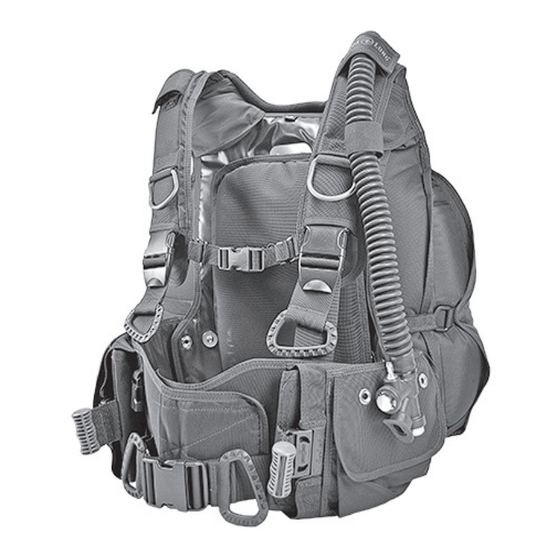
BC 1 COMPONENTS Inflator Accessory D-rings (4) Pull Knob Trim Pockets (2) Chest Strap Accessory Clip Knife Grommets (2) Cummerbund on each pocket SureLock 1 Weight System Front Crotch Strap John Line Ring Loop (2) Waist Buckle Inflator Dump Valve... -
Page 8: Product Description
BC 1 User's Manual PRODUCT DESCRIPTION BC 1 is a modular design buoyancy compensator consisting of three major components: harness, bladder and waistband w/ integrated weight system. Its rugged design makes it a perfect choice for military or public safety diving ap- plications. - Page 9 If you are unsure which regulator port is medium pressure (MP) or high pressure (HP), consult your regulator owner’s manual or your Authorized Aqua Lung Dealer or Distributor before attaching the hose.
- Page 10 BC 1 User's Manual GripLock™ Cylinder Band Components Micro Adjustment Bail Slot Lever Bail Macro Adjustment Threading the GripLock™ Cylinder Band If the GripLock cylinder band has been removed from the bail, re-thread using the following procedure: Insert the open end of the cylinder band into the large opening of the bail, around the slide bar and out of the small opening of the bail.
- Page 11 Adjusting the GripLock™ Cylinder Band WARNING: The BC must be completely deflated of air before adjusting the GripLock cylinder band. Failure to do so may result in the cylinder slipping during the course of a dive. NOTE: The GripLock cylinder band adjusts for all standard cylinder diameters and is ready for use with an aluminum 80 cf (7.25 inch / 184 mm) cylinder when the BC leaves the factory.
- Page 12 BC 1 User's Manual Securing the GripLock™ Cylinder Band NOTE: There is no need to wet the GripLock cylinder band prior to securing it to the cylinder. When properly adjusted, the cylinder band will retain it’s tension. If adjustment is necessary for a larger or smaller size cylinder (pre-set for use on an aluminum 80 cf cylinder 7.25 inch /...
- Page 13 3. Push the lever forward until it stops in the pre-locked position. NOTE: The pre-locked position ensures your fingers do not get caught in the lever. 4. Push the lever down into the locked position. Verify the lever is secured in the locked position.
- Page 14 BC 1 User's Manual Threading the Cam Buckle 1. Firmly grasp the metal D-ring with your left hand 2. While firmly holding the metal D-ring, TOP VIEW rotate the buckle back towards the webbing. The buckle should form an angle with the metal D-ring as shown in the top view 3.
- Page 15 Securing the Band to the Cylinder WARNING: The cylinder band will initially stretch as it becomes wet. Always wet the band before making the final adjustment; apply enough tension to ensure that the cylinder is completely secure. Test this connection before every dive. If the cylinder slips free from the BC during the dive, you may loose your air supply, which could lead to serious injury or death.
-
Page 16: Donning And Adjustment Procedures
BC 1 User's Manual 4. Pull the cam buckle closed so that it lies flat against the cylinder. Secure the end of the cylinder band with the hook & loop attachment. 5. Check the cylinder band is secure by pulling on the band while holding down the cylinder at the valve. - Page 17 Adjusting the Waistband Length - Nut and Bolt System Each side of the BC waistband is connected to the harness with two nut & bolt and washers combinations (all hardware is stainless steel). There are three positions that allow you to lengthen or shorten the waistband, with the outer grommets being the longest setting.
- Page 18 BC 1 User's Manual Adjusting the Chest Strap The chest strap fits across your sternum and keeps the shoulder straps from slipping to the sides, ensuring a comfortable and secure fit. Before donning the BC, loosen and disconnect the chest strap. After donning the BC, connect the chest strap and tighten by pulling on the free ends of the straps.
-
Page 19: Weight Integration Features
WEIGHT INTEGRATION FEATURES Your BC comes equipped with either a Hook and Loop or SureLock 1 Integrated Weight System. The SureLock 1 weight pouches are secured with a mechanical locking mechanism. The Hook and Loop weight pouches are secured with hook material on the pouches to loop material on the BC pockets. - Page 20 BC 1 User's Manual Maximum Weight Capacity The Hook and Loop or SureLock 1 weight system features two interchangeable weight pouches which can be filled with either block weights or “soft weight” (pouches containing lead shot), in increments of 4 pounds or less. For ease of operation, low-profile block weights are strongly recommended.
- Page 21 & loop (C). Aqua Lung recommends that the pouches be completely filled with four separate block weights (two per compartment); however, if you need to partially fill the pouch, load the bottom compartment first.
- Page 22 Installing the Hook and Loop Weight Pouches CAUTION: Aqua Lung strongly recommends that you do not attempt to don your BC when it is fully loaded with weight. You may otherwise risk injury due to muscle strain or a temporary loss of balance.
- Page 23 Installing the SureLock 1™ Weight Pouches CAUTION: Aqua Lung strongly recommends that you do not attempt to don your BC when it is fully loaded with weight. You may otherwise risk injury due to muscle strain or a temporary loss of balance.
- Page 24 BC 1 User's Manual Releasing the Weight Pouches Unlike a weight belt, which has only one release mechanism, each weight pouch is connected to the BC independently of the other and must be released separately. This provides you with the option of being able to jettison one pouch at a time, thereby maintaining better control of your ascent rate in an emergency.
- Page 25 BC has been secured to the cylinder. The non-releasable weight pockets are designed to hold single rectangular block weights. To avoid accidental loss of weight, Aqua Lung strongly advises against using small bullet-shaped weights and soft weight. Refer to the Weight Capacity Chart for maximum non-releasable weight capacity.
-
Page 26: Inflation Methods
BC 1 User's Manual INFLATION METHODS Power Inflation For the power inflator to operate, the medium pressure (MP) inflator hose must be connected. To connect the MP hose, grip the grooved sleeve at the connection fitting (A) with your thumb and forefinger and slide the sleeve back. Place the connection fitting over the quick disconnect fitting (B) on the inflator and firmly push inward while releasing the sleeve. -
Page 27: Deflation Methods
DEFLATION METHODS Throughout the course of a dive, it will be necessary to release air from the BC using one of the three methods described in the following instructions. Each method uses a valve that is in a different location. The method you choose at any time may depend on whether you are making your initial descent feet- first, head-first or maintaining neutral buoyancy underwater. - Page 28 BC 1 User's Manual Deflation (Dump Valve) Your BC comes equipped with a combination dump valve / over pressure relief valve (OPRV). The primary function is to relieve excess air pressure inside the bladder. If the internal pressure exceeds the spring pressure, the OPRV auto- matically opens to release air, preventing damage to the BC.
-
Page 29: Buoyancy And Cylinder Capabilities
BC. BC Buoyancy BC Single BC Double Cylinder Capacity Cylinder Capacity NOTE: The BC tag above is an example only. Reference the specific tag located on your model BC. BC 1 Cylinder Chart BC 1 Size Cylinder Capacity... - Page 30 BC 1 User's Manual Double Cylinder Set-up Before adapting your BC for use with double cylinders, it is important to compare the buoyancy of your particular BC size and model with the specifications of the cylinders, the amount of weight you will carry, and the type of exposure suit you will wear.
-
Page 31: Pre-Dive Inspection
NEVER dive with a BC that shows signs of damage to its bladder, valves or any components until it has received a complete inspection and service from an Authorized Aqua Lung Dealer or Distributor. 1. Visually inspect the entire BC for cuts, punctures, frayed seams, excessive abrasion, damaged or missing hardware and other damage of any kind. -
Page 32: Post-Dive Care And Maintenance
BC 1 User's Manual POST-DIVE CARE & MAINTENANCE 1. Avoid prolonged exposure to direct sunlight and extreme heat. Nylon fabric can quickly fade when exposed to the sun’s ultraviolet rays, and extreme heat may damage the welded bladder seams. 2. Avoid repeated or prolonged use in heavily chlorinated water, which can cause the BC fabric to discolor and decay prematurely. -
Page 33: Dealer Inspection And Service
DO NOT attempt to perform any disassembly or service of your BC. Service requiring disassembly must only be performed by a factory-trained Aqua Lung technician. To obtain service or repair, see an Authorized Aqua Lung Dealer or Distributor. 1. It cannot be assumed that the BC is in good working order on the basis that it has received little use since it was last serviced. - Page 34 BC 1 User's Manual Annual Service and Inspection Record Purchase Date: BC Model: Serial Number: Serial # Serial # is located BC Tag DATE TECHNICIAN TECHNICIAN STAMP NAME & NUMBER SIGNATURE...
-
Page 35: Warranty Information
For detailed information on product warranties, please refer to the Terms and Conditions Section of the Aqua Lung Military and Professional Buyers Guide. The buyers guide can be viewed or downloaded from the Aqua Lung Military and Professional website at www.aqualung.com/militaryandprofessional... - Page 36 BC 1 Buoyancy Compensator User's Manual 2340 Cousteau Court • Vista, CA 92081 Phone (760) 597-5000 • Fax (760) 597-4900 www.aqualung.com/militaryandprofessional ©2016 Aqua Lung International...
Need help?
Do you have a question about the BC 1 and is the answer not in the manual?
Questions and answers