Sign In
Upload
Download
Table of Contents
Contents
Add to my manuals
Delete from my manuals
Share
URL of this page:
HTML Link:
Bookmark this page
Add
Manual will be automatically added to "My Manuals"
Print this page
×
Bookmark added
×
Added to my manuals
Manuals
Brands
Vetus Manuals
Engine
D-LINE VD4.120
Operation manual
Vetus D-LINE VD4.120 Operation Manual
Marine diesel engines
Hide thumbs
1
2
3
4
5
6
7
8
9
10
11
12
13
14
15
16
17
18
19
20
21
22
23
24
25
26
27
28
29
30
31
32
33
34
35
36
37
38
39
40
41
42
43
44
45
46
47
48
49
50
51
52
53
54
55
56
57
58
59
60
61
62
63
64
65
66
67
68
69
70
71
72
73
74
75
76
77
78
79
80
81
82
83
84
85
86
87
88
89
90
91
92
93
94
95
96
97
98
99
100
101
102
103
104
105
106
107
108
109
110
111
112
113
114
115
116
117
118
119
120
121
122
123
124
125
126
127
128
129
130
131
132
133
134
page
of
134
Go
/
134
Contents
Table of Contents
Troubleshooting
Bookmarks
Table of Contents
Table of Contents
1 Safety Measures
Warning Indications
Preventing Fire and Explosion
Prevention of Injury
When Problems Occur
2 Introduction
Data Tag
Serial Number, Cylinder Numbering and Direction of Rotation
Identification of Engine Parts D4
Identification of Engine Parts D6
Control Lever
3 First Commissioning
4 Running-In
5 Use
General Guidelines
Starting
Cruising
Stopping
6 Maintenance
Introduction
Maintenance Schedule
Checking Engine Oil Level
Checking Coolant Level
Checking and Cleaning the Raw Water Strainer
Draining of Water from the Water Separator/Fuel Filter
Engine Oil Change
Battery, Cables and Connections
Gearbox Oil Level Check
Changing the Gearbox Oil
Fuel Filter Replacement
Flexible Engine Mounts, Hose Connections and Fasteners
Checking the V-Belts
Raw Water Pump Inspection
Air Filter Replacement
Checking the Starter Motor and Alternator
Checking Valve Clearance
Coolant Replacement
Cleaning the Heat Exchanger
Cleaning the after Cooler
7 Lay-Up / Winter Storage Procedure
8 Recommissioning after Lay-Up or Winter Storage
9 Troubleshooting
9 Troubleshooting
Engine Cranks but will Not Start, no Smoke from Exhaust
Engine will Not Crank
Engine Cranks but will Not Start, Smoke from Exhaust
Engine Starts but Runs Unevenly (Rough Idling) or Stalls
Engine Does Not Reach Maximum Rpm under Load
Engine Not Firing on All Cylinders
Engine Overheats
Engine Has Little or no Oil Pressure
Engine Oil Consumption Excessive
Black Exhaust Smoke (Idling)
Blue Exhaust Smoke (Idling)
Fuel Consumption Excessive
Black Exhaust Smoke (at Load)
White Exhaust Smoke (at Full Load)
Burnt Oil Trace in Exhaust Line
Idle Speed >750-800 RPM
10 Technical Data
Engine Specifications
Gearbox Specifications
Torque Wrench Settings
11 Operating Media
Fuel
Lubricating Oil
Coolant
12 Wiring Diagrams
13 Overall Dimensions
14 Parts for Maintenance
15 Index
Advertisement
Quick Links
1
Maintenance Schedule
2
Engine Specifications
3
Wiring Diagrams
Download this manual
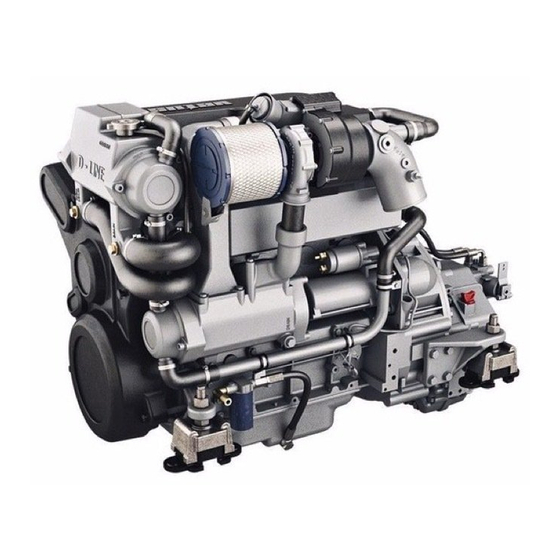
D-LINE
Marine Diesel Engines
Operation manual
VD6.210
VD4.120
VD6.170
VD4.140
VD6.210
360602.01
Table of
Contents
Previous
Page
Next
Page
1
2
3
4
5
Advertisement
Chapters
Table of Contents
5
9 Troubleshooting
99
Table of Contents
Need help?
Do you have a question about the D-LINE VD4.120 and is the answer not in the manual?
Ask a question
Questions and answers
Related Manuals for Vetus D-LINE VD4.120
Engine Vetus VF5 Service Manual
Vf4/vf5 series marine diesel engine (80 pages)
Engine Vetus VF4 Service Manual
Vf4/vf5 series marine diesel engine (80 pages)
Engine Vetus VF4.170E Installation Manual
Vf4 series vf5 series (72 pages)
Engine Vetus VF4.145 Operation Manuals
(128 pages)
Engine Vetus D-LINE VD6.170 Operation Manual
Marine diesel engines (134 pages)
Engine Vetus m3.10 Operation Manual
(156 pages)
Engine Vetus M Series Operation Manual
Marine diesel engines (148 pages)
Engine Vetus M2.C5 Operation Manual
(76 pages)
Engine Vetus M4.15 Operation Manual
(80 pages)
Engine Vetus DEUTZ DT44 Operation Manual
(88 pages)
Engine Vetus M3.28 Operation Manual
(76 pages)
Engine Vetus EAIR05024 Installation Manual
(84 pages)
Engine Vetus M4.15 Operation Manual
(72 pages)
Engine Vetus M2.02 Operation Manual
(120 pages)
Engine Vetus M4.55 Operation Manual
(100 pages)
Engine Vetus DT4.70 Operation Manual
(144 pages)
This manual is also suitable for:
D-line vd4.140
D-line vd6.170
D-line vd6.210
Table of Contents
Print
Rename the bookmark
Delete bookmark?
Delete from my manuals?
Login
Sign In
OR
Sign in with Facebook
Sign in with Google
Upload manual
Upload from disk
Upload from URL


Need help?
Do you have a question about the D-LINE VD4.120 and is the answer not in the manual?
Questions and answers