Table of Contents
Advertisement
Quick Links
Advertisement
Chapters
Table of Contents
Troubleshooting

Subscribe to Our Youtube Channel
Related Manuals for Vetus M4.15


Summary of Contents for Vetus M4.15
- Page 1 M4.15 M4.17 Operation manual...
- Page 2 M4.17 VD01047...
-
Page 3: Serial Numbers
Operation manual M 4 . 1 5 M 4 . 1 7 Serial numbers Engine serial number Vetus: Mitsubishi: Gearbox serial number: Please enter the serial numbers here. These numbers should be quoted when inquiring about Customer Service, Repairs or Spare Parts (see page 6). - Page 4 For the Guarantee Conditions, see the Vetus Diesel Service and The relevant accident prevention guidelines and other generally Warrantee Manual. accepted safety and industrial hygiene regulations must be observed.
-
Page 5: Table Of Contents
Contents Serial numbers Maintenance Cleaning the heat exchanger Checking engine rpm Checking the oil level Introduction Checking the coolant level Checking and cleaning the Winter lay-up raw water strainer Engine description Winter storage procedure Draining water from the water Recommissioning after winter General separator/fuel filter storage... -
Page 6: Introduction
Introduction Dear customer, Vetus diesel engines are designed both for pleasure and com- mercial craft. Consequently, a wide range of variants are offered to meet the requirements of specific cases. Your engine is appropriately equipped for your vessel, which means that not necessarily all components described in this manual are mounted to your engine. -
Page 7: Safety Measures
Introduction Safety measures All safety instructions in this manual are desig- • Never attempt to touch moving parts when the engine is run- nated by the accompanying symbol. Please fol- ning. low them carefully. • Never touch hot parts of the engine, and keep flammable materials well away from the engine. -
Page 8: Engine Description
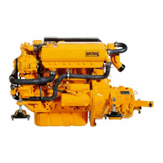
Engine description General VD01077 VD01048 VD01049 Engine data tag Engine data tag location Engine serial number The V engine serial number and per- The V engine data tag is attached to The M engine serial number is ETUS ETUS ITSUBISHI formance data are printed on the engine the valve cover. - Page 9 Vetus- The maximum engine speed adjustment Mitsubishi Service special- screw has been sealed to prevent this. ists only.
-
Page 10: Identification Of Engine Parts
Engine description Identification of engine parts Service side 1 Oil filler cap 2 Fuel pump air bleed nipple 3 Fuel supply pipe connection ø 8 mm 4 Fuel lift pump 5 Oil dipstick 6 Oil filter 7 Water separator/fuel filter drain plug 8 Water separator/Fuel filter 9 Gearbox filler cap... -
Page 11: Identification Of Engine Parts
Identification of engine parts Engine description Starter side 19 Calorifier connection 20 Gearbox drain plug 21 Gearbox 22 Starter motor 23 Raw water inlet ø 20 mm 24 Raw water pump 25 V-belt 26 Alternator 27 Filler cap for cooling system 28 Expansion tank 29 Heat exchanger 30 Cooling system drain plug... -
Page 12: Control Panels
Engine description Control panels VD00103 VD00102 Basic panel (model 22) Sailingboat panel (model 10) Fly-bridge panel (excl. voltmeter, model 21) 1 Tachometer/Operating hours counter 6 Warning light high coolant temperature 2 Voltmeter 7 Warning light battery charging 3 Starter pre-heat switch/lock 8 Indicator light pre-heating 4 Warning light high raw water temperature 9 Warning light gearbox low oil pressure *... -
Page 13: Use
General guidelines General guidelines for use Implementing the following recommendations will result in longer life and better performance and more economical operation of your engine. • Carry out the maintenance described regularly, including the ‘Daily procedures before starting’. • Use anti-freeze in the engine coolant all year long, this helps prevent corrosion as well as protecting against frost damage. -
Page 14: First Commissioning
Engine Oil 5 litres (1 UKgal) 15W40 API: CD, CE or CF4 CCMC: D4, D5 For example: - Vetus Marine Inboard Diesel Motor - Shell Super Diesel T VD01052 VD01053 Commissioning the engine Filling with engine oil Before starting the engine for the first time,... - Page 15 First commissioning Vetus engines are normally equipped with ZF-Hurth or Technodrive gearbox- In case your engine is equipped with another brand of gearbox follow the instructions given in the supplied own- ers manual. VD01034 VD01054 Filling gearbox with oil Fill the gearbox with oil.
- Page 16 First commissioning OOLANT 6.5 litres (1.4 UKgal) QUANTITY ATER HEATER If a water heater is connected to the engine and this heater is positioned above the upper side of the engine then bleeding of the heater will not take place automatically! Fill the heater sep- arately to bleed the cooling system (3/8”) completely.
-
Page 17: Running-In
First commissioning Running-in Never fill the fuel tank while FUEL the engine is running. Do spill fuel. Prevent unnecessary pollution. VD00002 Fuel Other preparations Running-in Ensure that the fuel tank is filled with • Check battery and cable connections. In order to ensure a long life for your diesel fuel. -
Page 18: Starting
Starting Before starting, check the follow- ALWAYS ing points: neutral • Engine oil level. gearbox gearbox • Coolant level. reverse half throttle, forward • Sea cock open. gearbox not engaged • Main switch ‘ ’. • Gearbox in ‘ ’ position. NEUTRAL forward reverse... -
Page 19: Pre-Heating
Starting Ambient Pre-heating time Temperature Above + 5°C (41°F) about 6 seconds +5°C to -5°C about 12 seconds (+41°F to +23°F) Below -5°C (23°F) about 18 seconds Maximum 1 minute pre-heating time VD00107 VD00108 Pre-heating Pre-heating time Turn the start key on the instrument panel The ideal pre-heating time depends on Turn the key further clockwise to the ‘... - Page 20 Starting ARNING ARNING Release the key if the engine does not Never turn the key to the ‘ ’ posi- START fire within 10 seconds. Wait until the tion while the engine is running. starter motor has stopped running Doing so will damage the starter motor. VD00109 completely before turning the key to the ‘...
-
Page 21: Cruising
With the engine stopped and the start key alarm buzzer. If this alarm buzzer sounds in the first position, the voltmeter should while running, S TOP THE ENGINE IMMEDIATE Idling speed, indicate 12 Volts. M4.15: 840 rpm M4.17: 840 rpm... -
Page 22: Stopping
Stopping VD00105 VD00106 VD01057 Electrical shutdown Mechanical shutdown Reduce engine speed to idle and shift the When the engine has stopped, turn the On the engine itself stopping is possible gearbox to ‘N ’. Turn the key entirely key to the ‘O ’... -
Page 23: Routine Maintenance
Introduction Routine Maintenance Introduction The following guidelines should be observed for daily and peri- odic maintenance. Perform each function at the indicated time interval. The intervals stated are for normal operational conditions. Service the unit more frequently under severe conditions. Failure to carry out maintenance can result in faults and perma- nent damage to the engine. -
Page 24: Maintenance Schedule
Routine Maintenance Maintenance schedule Every 10 hours or daily, before starting Every 500 hours, at least once every year Check engine oil level Gearbox oil change Check coolant level Check valve clearance Check water strainer Replace fuel filter Cleaning fuel lift pump After the first 50 hours Check V-belt Drain water from fuel filter... -
Page 25: Maintenance
Checking engine oil level Maintenance Daily, before starting. VD01058 VD00126 VD01052 Check oil level Oil level Topping up oil Turn the engine off. The oil level must be at or near the upper The oil filling cap is on top of the the valve The dipstick is located on the starboard mark on the dipstick*. -
Page 26: Checking The Coolant Level
Maintenance Checking coolant level Daily, before starting. VD01059 yyyyyyyyyyy (3/8”) yyyyyyyyyyy VD00144 VD01056 VD01055 Checking coolant level Topping up coolant Check the coolant level in the header tank. If necessary, top up. The internal cooling system can be filled This has to be checked when the engine is with a mixture of anti-freeze (40 %) and tap cold. -
Page 27: Checking And Cleaning The Raw Water Strainer
Checking and cleaning the raw water strainer Maintenance Daily, before starting. VD00125 CT30119 Checking the raw water strainer Cleaning the strainer Check daily whether there is any dirt in the Close the seacock before removing the lid Check the sealing between the lid and raw water strainer. -
Page 28: Draining Water From The Water Separator/Fuel Filter
Maintenance Draining of water from the water separator/fuel filter Every 100 operating hours. VD01060 VD00027 VD00107 Empty fuel filter Empty water separator Bleeding After the water separator/fuel filter has • Open the drain plug at the lower side of Empty the separately installed water sepa- been drained, the air has to be bled from the filter. - Page 29 Draining of water from the water separator/fuel filter Maintenance Every 100 operating hours. VD01061 VD01062 VD00109 Start the engine A second bleeding nipple is located at the Operate the starter switch until the engine Open the two bleeding nipples to speed fuel injection pump.
-
Page 30: Changing The Oil
Maintenance Engine oil change Every 100 operating hours. Engine oil change Change the engine oil every 100 hours of operation (together with engine oil filter replacement). If the engine runs less than 100 hours dur- ing the year the oil should be changed at least once a year. -
Page 31: Engine Oil Change
Engine oil change Maintenance Every 100 operating hours. : STM0051 MOUNT OF OIL IL FILTER CODE 5.6 litres (1.25 UKgal) OIL FILTER INCL VD00124 VD01065 VD01052 Oiling the oil seal Oil filter installation Refilling with oil Clean the contact surface of the gasket. Install the filter in accordance with the Refill the engine with new oil (for specifi- Lubricate the oil seal of the new filter ele-... -
Page 32: Battery, Cables And Cable Connections
Checking specific gravity Hydrometer operation Keep battery clean and dry. • Green dot visible - State of charge Every Vetus Maintenance-free battery has Remove battery cables (negative first). 65 % or more. a hydrometer (1) built into the cover. Clean battery posts (+ and -) and clamps •... -
Page 33: Battery, Cables And Cable Connections
Battery, cables and connections Maintenance Every 100 operating hours. Conventional batteries Conventional batteries Specific State of gravity charge 1.280 100% 1.200 recharge 1.120 recharge immediately VD00119 VD00120 Checking electrolyte level Checking specific gravity The gases emitted by the For conventional batteries it is required to Measure the electrolyte specific gravity of battery are explosive! Keep check the electrolyte level regularly. -
Page 34: Checking The Gearbox Oil Level
Oil level check (ZF-Hurth) Oil level check (Technodrive) Unscrew the dipstick out of the gearbox The oil level must between the two marks Vetus engines are normally equipped with housing. on the dipstick ZF-Hurth or Technodrive gearboxes. If necessary top up. -
Page 35: Changing The Gearbox Oil
Changing the gearbox oil Maintenance Every 500 operating hours. VD01043 VD01042 VD01034 Draining the oil Filling with new oil Or, if sufficient space below the gearbox is available, oil can be drained by removing Refill the gearbox to the correct level via Drain the oil with the aid of a separate the drain plug. -
Page 36: Checking Valve Clearance
Maintenance Checking valve clearance Every 500 operating hours. Mark on TDC mark gearcase cylinder 1 and 4 Injection timing mark TDC mark cylinder 2 and 3 VD01067 VD00130 Checking / adjusting valve clearance Remove rocker cover Locating TDC Checking the valve clearance must be Remove the 5 bolts of the rocker cover. -
Page 37: Check Valve Clearance
Checking valve clearance Maintenance Every 500 operating hours. 0.25 mm (0.010”) ALVE CLEARANCE NLET 0.25 mm (0.010”) XHAUST 1.2 x 6.5 VD01068 VD00146 Adjusting valve clearance Cylinder numbering • Check valve clearance at cylinder 1 and Cylinders are numbered consecutively, adjust if necessary. -
Page 38: Replacing The Fuel Filter
Maintenance Fuel filter replacement Every 500 operating hours. : STM3690 UEL FILTER CODE VD01017 VD00154 VD00133 Fuel filter removal Fuel filter installation The fuel filter is to be replaced as a unit. • Clean any debris from the filter carrier •... -
Page 39: Cleaning Fuel Lift Pump
Cleaning fuel lift pump Maintenance Every 500 operating hours. : STM4050 UEL FILTER CODE Fuel filter STM7220 VD00109 Fuel lift pump Bleeding Start the engine • Check, and if necessary clean, filter After replacing the fuel filter and cleaning Operate the starter switch until the engine inside the fuel lift pump. -
Page 40: Checking The V-Belt
Maintenance Checking the V-belt Every 500 operating hours. : STM7966 BELT CODE VD00034 VD00128 VD00129 Inspection V-belt Checking tension Tensioning V-belt Inspect the belt for wear and tear (fraying Check tension of the V-belt by applying Loosen the bolt of the adjustment bracket and cracking). -
Page 41: Checking Flexible Engine Mounts
Flexible engine mounts, hose connections and fasteners Maintenance Every 500 operating hours. VD00160 VD01069 Check flexible engine mounts Inspection hose connections Check fasteners Check the bolts which secure the damper Inspect all hose connections of the cool- Check tightness of all fasteners, bolts and element, the mounting bolts to engine bed ingsystem. -
Page 42: Raw Water Pump Inspection
Maintenance Raw water pump inspection Every 1000 operating hours. 1.6 x 6.3 VD01070 VD01071 VD01031 Raw water pump inspection Pump cover removal Impeller removal The rubber impeller of the outboard water Inspection where appropriate changing is • Slide the impeller off of the shaft using pump is not proof against running dry. - Page 43 Raw water pump inspection Maintenance Every 1000 operating hours. : STM8061 : STM8002 MPELLER CODE ASKET CODE VD00127 VD00004 VD00159 Impeller inspection Re-install the impeller Replacing the pump cover • Inspect the impeller for damage. • The impeller should be lubricated with •...
-
Page 44: Coolant Replacement
Maintenance Coolant replacement Every 1000 operating hours. Coolant replacement The coolant has to be replaced every 1000 operating hours or at least once every two years. N.B. Replacing the coolant may also be necessary as part of the winter storage procedure;... - Page 45 Coolant replacement Maintenance Every 1000 operating hours. OOLANT 6.5 litres (1.4 UKgal) QUANTITY ATER HEATER If a water heater is connected to the engine and this heater is positioned above the upper side of the engine than bleeding of the heater will not take place automatically! Fill the heater sep- arately to bleed the cooling system (3/8”)
-
Page 46: Cleaning The Heat Exchanger
Maintenance Cleaning the heat exchanger VD01073 VD01059 VD01076 Remove the drain plug Removal of bolts out of the end covers • Close the seacock and detach the • Remove the filler cap from the top of the Take out both central bolts from the end water inlet hose from the sea water heat exchanger housing to allow air into covers and take the end covers with the O-... -
Page 47: Cleaning Heat Exchanger
Cleaning the heat exchanger Maintenance VD01075 VD01021 STM7217 Remove heat exchanger Cleaning the heat exchanger Slide the heat exchanger out of the hous- Clean the heat exchanger: Use a pipe ing. cleaner to remove fouling in the pipes. Then rinse the heat exchanger pipes with clean water. - Page 48 Maintenance Cleaning the heat exchanger : STM6113 (2 RING CODE VD00157 VD00143 Replacing heat exchanger Replacing the end covers Replace the heat exchanger in the original position in the heat exchanger housing. Fit the end covers in the housing; the con- Tighten up the bolts when both covers are Use new O-rings (61 x 2.5 mm) which nector cover is fitted with a locating pin so...
-
Page 49: Checking Engine Rpm
Checking engine speed Maintenance ARNING Increasing RPM The maximum engine speed adjust- ment screw has been correctly set at Minimum the factory and sealed. DO NOT speed adjust- ment screw attempt to remove this seal. Maximum speed adjust- ment screw Lead seal VD00134 VD00145... -
Page 50: Winter Lay-Up
Winter lay-up Winter storage procedure VD01060 VD00136 Fuel system Running with protective fuel mixture Drain water from water Connect the fuel supply pipe to a can filled * Engine oil with protective properties. separator/fuel filter and the fuel tank. with a mixture of one (1) part of engine oil* E.g. - Page 51 Winter storage procedure Winter lay-up VD01063 VD00125 Lubrication system Raw water cooling system With the engine still at operating tempera- Close the seacock before removing the lid Check the seal between the lid and hous- ture: (If not, run the engine until warm, of the water strainer.
- Page 52 Winter lay-up Winter storage procedure VD01059 VD00139 VD001xx Fresh water cooling system Electrical system Charging the batteries To avoid corrosion during winter storage Disconnect the battery cables. Charge batteries during winter lay-up reg- the cooling system must be filled with an ularly if required! antifreeze/water mixture (or a coolant).
-
Page 53: Recommissioning After Winter Storage
Recommissioning after winter storage Winter lay-up Check that the lid of the raw water Open the sea cock. strainer is reinstalled. VD00125 VD00138 Check that the lid of the raw water Check the coolant level. (page 24) pump and drain plugs are rein- stalled. - Page 54 Winter lay-up Recommissioning after winter storage Drain the water from the water sepa- Open the fuel valve. rator/fuel filter. (page 26) VD00027 VD00137 Drain the water from the fuel tank. Make sure that the batteries are fully charged. (pages 30, 50) VD00141 CT40063 Install a new fuel filter.
- Page 55 Recommissioning after winter storage Winter lay-up Start the engine. Check the fuel system, the cooling system and the exhaust for leakage. VD01078 Stop the engine and change the oil of the gearbox. (page 33) VD01043 Check the operation of the instru- ments, the remote control and the gearbox.
-
Page 56: Troubleshooting
Troubleshooting General Engine faults are in most cases caused by improper operation or insufficient maintenance. In case of a fault, always check first that the operation and main- tenance instructions have been followed. In the following tables information is given about the possible causes of faults and suggested remedies. -
Page 57: Troubleshooting
Fault finding table Troubleshooting 1 Engine will not crank 2 Engine cranks but will not start, no smoke from exhaust Possible fault Remedy Possible fault Remedy Faulty or discharged battery. Check / recharge batte- Fuel stop valve closed. Open. ry and check engine (Nearly) Empty fuel tank. - Page 58 Troubleshooting Fault finding table 3 Engine cranks but will not start, smoke from exhaust 4 Engine starts but runs unevenly (rough idling) or stalls Possible fault Remedy Possible fault Remedy Air in fuel system. Check and bleed. (Nearly) Empty fuel tank. Refill.
- Page 59 Fault finding table Troubleshooting 5 Engine does not reach maximum rpm under load 6 Engine overheats Possible fault Remedy Possible fault Remedy Air in fuel system. Check and bleed. Faulty injector/injection pump. Check, replace if requi- Fuel filter clogged with water Check or replace.
- Page 60 Troubleshooting Fault finding table 7 Engine not firing on all cylinders 8 Engine has little or no oil pressure Possible fault Remedy Possible fault Remedy Air in fuel system. Check and bleed. Oil level too low. Increase level. Fuel filter clogged with water Check or replace.
- Page 61 Fault finding table Troubleshooting Blue exhaust smoke (idling) White exhaust smoke (at full load) Possible fault Remedy Possible fault Remedy Oil level too high. Lower level. Air in fuel system. Check and bleed. Excessive inclination of engine. Check / Adjust. Faulty injector/injection pump.
-
Page 62: Technical Data
Technical data Engine specifications Model M4.15 M4.17 Model M4.15 M4.17 General Maximum output Make Vetus Mitsubishi at the flywheel (ISO 3046-1) 24.3 kW (33 hp) 30.9 kW (42 hp) Number of cylinders at the prop shaft (ISO 3046-1) 23.6 kW (32.1 hp) 30 kW (40.8 hp) -
Page 63: Engine Specifications
Engine specifications Technical data Model M4.15 M4.17 Model M4.15 M4.17 Oil lubrication system Exhaust system Oil capacity, max. Exhaust diameter 50 mm without oil filter 5.4 litres (1.2 UKgal) Exhaust back pressure at specified output with oil filter 5.6 litres (1.25 UKgal) max. - Page 64 Technical data Torque wrench settings Wrench Torque Screw connection Size Diameter Pitch (kgm) (ft.lbf) Cylinder head bolt 1.25 ±5 ±0.5) (65 ±3.5) Connecting rod nut 34.8 ±2.5 (3.55 ±0.25) (26 ±2) Fly-wheel bolt 1.25 ±5 (13.5 ±0.5) (98 ±3.5) Crank shaft pulley nut ±25 (17.5 ±2.5)
-
Page 65: Lubricating Oil
(-13°F up to +86°F) - SAE 15W40 for temperatures of -20°C up to +35°C (-4°F up to +95°F) For example: Vetus Marine Inboard Motor Oil *) ATF : AutomaticTransmission Fluid; Shell Super Diesel T Transmissie olie type A, Suffix A. -
Page 66: Fuel
Operating media Fuel Fuel Quality Grade Winter-grade fuel Use commercially available diesel fuel with less than 0.5% sulfer Waxing may occur at low temperatures, clogging the fuel system content. If the sulfur content is higher than 0.5%, the intervals and reducing engine efficiency. between oil changes should be halved e.g. -
Page 67: Coolant
Coolant Operating media Coolant fluid Water quality for coolant preparation Use preferably tap water. The preparation and monitoring of coolant in inter-cooled engines is especially important because corrosion, cavitation and If an other available fresh water is used; the values given below freezing can lead to engine damage. -
Page 68: Wiring Diagrams
Wiring diagram Engine with panel ‘model 22’ Starter switch Warning lights Tachometer/ Voltmeter hour counter Alarm buzzer Plug Socket (Engine) Fuse Battery switch Battery Starter motor Glow plugs Fuel lift Stop Alternator Temperature Oil pressure Temperature solenoid switch switch switch pump VD00147... - Page 69 Options, panel ‘model 10’ Wiring diagram Starter switch Warning lights Alarm buzzer Plug VD00148...
-
Page 70: Overall Dimensions
Overall Dimensions FUEL RETURN ø 8 mm EXHAUST ø 50 mm FUEL SUPPLY ø 8 mm M4.15 / M4.17 1:10... - Page 71 Service- und Garantieheft / Livret Garantie et Service / Deutsch / Français / Manual de servicio y garantía / Libretto di assistenza e garanzia Español / Italiano) STM0091 Onderdelenboek / Parts manual M4.15 / M4.17 (Nederlands / English) STM0144 Service manual M4.15 / M4.17 (English)
- Page 72 FOKKERSTRAAT 571 - 3125 BD SCHIEDAM - HOLLAND - TEL.: +31 (10) 4377700 FAX: +31 (10) 4621286 - 4373474 - 4153249 - 4372673 - E-MAIL: DIESEL@ VETUS.NL STM0119 05-00 English Printed in the Netherlands...
Need help?
Do you have a question about the M4.15 and is the answer not in the manual?
Questions and answers